Densification and Structure Evolution of ZrB2-ZrO2 Composites Prepared by Plasma Activated Sintering using ZrB2@ZrO2 Powder
2021-04-16YANGHaitaoZHANGJianLIJunguoSHENQiang
YANG Haitao, ZHANG Jian, LI Junguo, SHEN Qiang
(State Key Laboratory of Advanced Technology for Materials Synthesis and Processing, Wuhan University of Technology, Wuhan 430070, China)
Abstract: The densification and the structure evolution of the plasma activated sintered (PAS sintered)ZrB2-ZrO2 composite via the ZrO2-coated ZrB2 powder (ZrB2@ZrO2) prepared by in situ passivation method were investigated. The composition and microstructure were characterized by XRD, Raman, SEM, and EDS techniques. The coated powder has excellent sintering performance. The relative density of the composite reaches above 90% at 1 200 ℃, and the main sintering process occurs between ZrO2 particles. While at above 1 500 ℃, the relative density reaches above 95% and the main sintering process occurs between ZrB2 and ZrO2 particles. With the increase of ZrO2 coating content, the structure of the sintered body changes from ZrB2 continuous network structure to island structure. When the content is 20%, an island structure is formed. Increasing the ZrO2 content further causes the overheating of ZrO2. Thus, the best sintering performance reaches when the coating content is 20wt%.
Key words: ZrB2; ZrO2; coating content; densification; structure evolution
1 Introduction
Zirconium diboride (ZrB2) based composite is attractive for use in ultra-high temperature field due to its unique combination of physical and mechanical properties such as the high melting point and relative low density. However, the low sinterability, low fracture toughness and poor oxidation resistance of the monolithic ZrB2limit its wide applications[1-3].
The introduction of second phase, such as SiC[4-6],Si3N4[7], ZrC[8], and ZrO2[9-13], was the common strategy to overcome the above disadvantages. Zhanget al[4]prepared ZrB2-SiC composite by pressureless sintering.It has an excellent oxidation resistance whose mass gain was only 5 mg·cm-2after oxidized at 1 500 ℃for 30 min. Liet al[13]fabricated a series of ZrB2-ZrO2composites by hot pressing. They found that the relative density of the composite increase with the ZrO2content. ZrB2-30vol% ZrO2composite provided the optimal combination of dense microstructure, high hardness of 22.7 GPa and high fracture toughness of 6.5 MPa·m1/2.
The introduction of a second phase as a powder coating, especially for the nanoscale one, contributes to improving the mixing uniformity of each phase and optimizing the structure of composite, thus further improving the performance. Anget al[14]prepared the ZrB2@(ZrO2/C) composite powder using sol-gel method. The ZrO2/C coating reacted to produce the nanoscale ZrC during the sintering process, promoted the densification and inhibited the grain growth. Guoet al[15]fabricated the ZrB2@(Zr/Al) composite powders using ball milling process. Then the ball milled powers were mixed with graphite powders and SiC powders and sintered to prepare the ZrB2-SiC-ZrAlC composite ceramics. The Zr/Al coating reacted with graphite to in situ produce layered ZrAlC compound. A more uniform microstructure of the ceramic was obtained than that of the ceramic using the un-milled powder, thus gained a high toughness of 5.96 MPa·m1/2. Songet al[12,16]successfully prepared the ZrB2@ZrO2composite powder by co-precipitation method. The composite powder was found to promote the densification compared with that of uncoated one. The relative density of the Zr-B2@10wt% ZrO2composite ceramic reached 95% after sintered at 1 900 ℃. The thermal shock resistance and the oxidation resistance were also improved.
However, the coating quality of the above composite powders is not satisfying. The various coatings prepared by the sol-gel, ball-milling, and the co-precipitation methods have incomplete coverage and the thicknesses are not uniform. The composite powder with a high coating quality would further optimize the structure of the composites. In our previous work[17], the ZrB2@ZrO2composite powder with uniform thickness,full coverage and controllable coating content was prepared by in situ passivation reaction. The passivation reaction transformed the surface of ZrB2powder to the ZrO2coating. The coating content was controllable by adjusting reaction time.
Based on these, a series of ZrB2@ZrO2composite powders prepared by in situ passivation reaction were used here. Then the densification behavior of the coated powders was studied. And the influence of coating content on sintering properties, structural evolution and mechanical properties of the ZrB2@ZrO2composite materials would be further analyzed.
2 Experimental
2.1 Synthesis of the coated powders
As-received ZrB2powder shown in Fig.1(a)with an average size 10-15 μm and clean surface was provided by Qinhuangdao ENO High-Tech Material Development Co., Ltd. in China. The mixture of NaOH and H2O2solution (total volume, 60 mL) was filled in a 100 mL Teflon liner at room temperature. The NaOH and H2O2concentration were 1 mol·L-1and 2 mol·L-1,respectively. Then a Teflon tube loaded with 2 g ZrB2powders was transferred into the Teflon liner. The Teflon liner was placed in an autoclave and preheated at 140 ℃ for 4 h. After preheated, the autoclave was taken out and inversed for several times to keep the sufficient contact between the powder and the mixed solution,and then moved back to the furnace for several hours(2-24 h). The coating content was controlled by the reaction time. After cooling to room temperature, the mixture was transferred from the Teflon liner to a beaker that filled with 3 000 mL water. After standing for 30 min, the liquid supernatant and the solid product were separated. The collected solid product was then rinsed with deionized water and ethanol for five times,and finally dried at 80 ℃ for 24 h.
2.2 PAS sintering
The coated powders and the unco ated powders with the same composition were loaded into cylindrical graphite (inner diameter, 20 mm) dies that lined with flexible graphite foils. The sintering process was conducted by the plasma activated sintering equipment(PAS, ED-PAS 111 equipment, Elenix, Zama Shi, Japan) at different sintering temperatures for 10 min under a uniaxial load of 40 MPa in Ar atmosphere with a sintering speed of 100 ℃·min-1.
2.3 Characterizations
The compositions of the coated powder and the sintered composites were analyzed by X-ray diffraction(XRD, RU-200B/D/MAX-RB, Rigaku Corporation,Japan) using Cu Kα1 radiation and Raman spectra(LabRAM HR800, Horiba, USA) using the 325 nm laser excitation. The scanning range of XRD is 25°-45° and the scanning speed is 4 °·min-1. The Raman spectra were recorded in the range of 50-700 cm-1. The whole coating content was calculated by the RIR method using the XRD results of the sintered composite.The morphology of the coated powder and the microstructure of the composites were characterized by the field emission scanning electron microscopy (FE-SEM,Quanta 250, FEI, USA) equipped with the energy dispersive X-ray spectroscopy (EDS, 51-XMX1005, Oxford Instruments Inc., UK). The density of the sintered composites was measured by Archimedes principle.The volume electrical resistivity of the composites was tested by four-point probe method using the Hall measurement system (H-50, MMR Technologies Inc.).The hardness of the composites was tested by Vickers hardness tester (Wolpert 430SV, Wolpert Wilson Instruments, Aachen, Germany) with a load of 3 kg for 15 s. Fracture toughness (KIC) was evaluated by a single-edge notched-beam test with a 16-mm span and a crosshead speed of 0.05 mm·min-1using 2 mm×4 mm×20 mm test bars on a hydraulic universal testing machine (Instron 5966, UK). The mechanical tests were repeated five times.
3 Results and discussion
3.1 Characterization of the coated powder
The morphology of the coated powder with the reaction time of 24 h is shown in Fig.1(b). Different from the smooth and clean surface of the raw ZrB2powder(Fig.1(a)), the surface of the coated powder exhibits a large amount of homogeneously distributed short rode-like crystals with sub-micron scale size. And the coverage of the coating approaches 100%. The phase analysis in Fig.1(c) shows that the product is composed of monoclinic zirconia (m-ZrO2), tetragonal zirconia(t-ZrO2), and ZrB2phase.

Fig.1 The morphologies of raw ZrB2 powder(a) and ZrB2@ZrO2 powder(b) with the reaction time of 24 h; (c) XRD pattern of ZrB2@ZrO2 powder

Fig.2 (a) Shrinkage curve of the ZrB2@ZrO2 composite using the coated powder with the reaction time of 24 h; (b) Relative densities of the composite at different sintering temperatures for 10 min under a pressure of 40 MPa

Fig.3 (a) XRD patterns of the ZrB2@ZrO2 composites sintered at different temperatures using the coated powder with the reaction time of 24 h. The ZrO2 coating content is calculated to be about 30wt% by the RIR method; (b) Raman spectrum of the coated composite sintered at 1 700 ℃; (c) XRD patterns of the coated composites sintered at 1 700 ℃ with and without the BN segregation during sintering
3.2 Effect of temperature on densification behabior
3.2.1 Shrinkage and relative density
Fig.2(a) shows the shrinkage curve of the ZrB2@ZrO2composite using the coated powder with the reaction time of 24 h. As can be seen, the volume shrinkage is not apparent when the temperature is below 800 ℃.The shirinkage starts at 8 00-1 200 ℃, which corresponds to the sharp contraction of ZrO2in this temperature range[18]. The shrinkage ends at 1 200-1 500 ℃.At temperatures above 1 500 ℃, the volume expands slightly.
Fig.2(b) shows the relative densities of the ZrB2@ZrO2composite sintered at different temperatures.When calculating the relative density, the theoretical density is obtained by the mixing rules using the content of the composition derived from the RIR results of Fig.3(a). The relative density is 91%-92% and changes little when the temperature is 1 200-1 500 ℃. With the temperature rises, the relative density increases significantly, reaching 95% at 1 700 ℃.
3.2.2 Phase and composition
Fig.3 exhibits the phase and composition analysis of the ZrB2@ZrO2composites. Fig.3(a) is the XRD results of the coated composite sintered at different temperatures. The main phases are ZrB2andm-ZrO2. When the sintering temperature is above 1 600 ℃, there exists a small amount oft-ZrO2evidenced by the Raman spectrum (Fig.3(b)). The Raman spectrum contains the strong characteristic peaks ofm-ZrO2and the weak characteristic peaks oft-ZrO2(148 and 221 cm-1)[19].The ZrO2coating content is calculated to be about 30wt% by the RIR method.
The content oft-ZrO2is related to the diffusion and doping of carbon element derived from the graphite die during sintering[20]. The higher the sintering temperature, the more the carbon element introduces into the sample which results in the obvious inhibition of martensitic transformation of ZrO2. Thus, the content oft-ZrO2increases with the sintering temperature. When the contacts between the coated powders and graphite die is prohibited by the BN spraying, the content oft-ZrO2is significantly decreased as shown in Fig.3(c).
3.2.3 Microstructures of the coated composites
Fig.4 exhibits the fracture morphologies of the ZrB2@ZrO2composites with 30wt% ZrO2sintered at different temperatures. When the sintering temperature is 1 200-1 600 ℃, the ZrB2particle shows an island distribution and ZrO2particle is a continuous network structure. The ZrO2particle grows from sub-micron scale to several microns with the increased sintering temperature. With the further increase of temperature(above 1 600 ℃), the characteristic of the small ZrO2particles disappears. The ZrO2grain coarsening behavior is apparent.
Fig.5 shows the polished surface of the ZrB2@ZrO2composites with 30wt% ZrO2sintered at different temperatures. When the temperature is below 1 600 ℃,the surface exhibits obvious isolated ZrB2particles and the porous continuous ZrO2particles (Figs.5(a) and5(d)), which is consistent with the fracture morphologies (Fig.4). When the temperature is 1 700-1 800 ℃(Figs.5(b) and 5(e)), the continuous ZrO2particles transform into a whole and the characteristic of small ZrO2particles disappears. The ZrB2still shows an island distribution from the corresponding EDS maps of B element (Figs.5(c) and 5(f)). There exists large amount of pores between ZrB2and ZrO2(the red circle)and a few pores between ZrO2and ZrO2particles (the green circle) when sintered at 1 700 ℃ (Fig.5(b)). The pores between ZrO2and ZrO2particles results from the oversintering of the ZrO2[21,22]at such high temperature. While at 1 800 ℃, the number of pores between ZrB2and ZrO2decreases and the pores between ZrO2and ZrO2particles still remains.
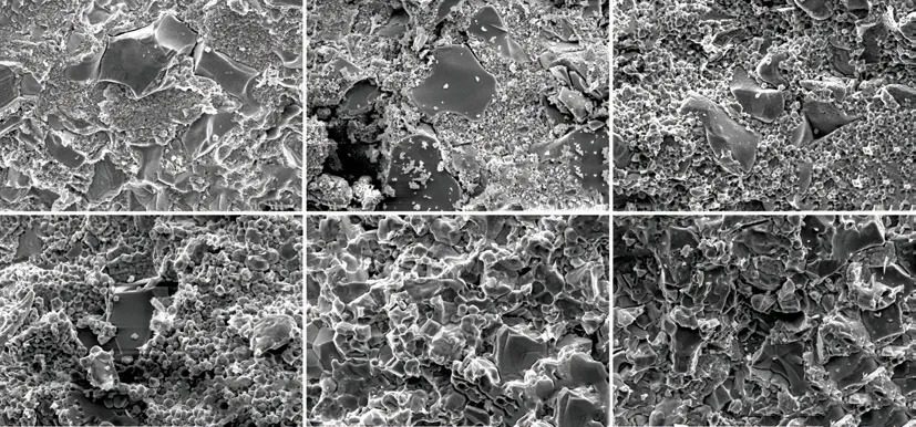
Fig.4 Fracture morphologies of the ZrB2@ZrO2 composites with 30wt% ZrO2 sintered at (a)1 200, (b)1 400, (c)1 500, (d)1 600, (e)1 700,and (f)1 800 ℃ for 10 min
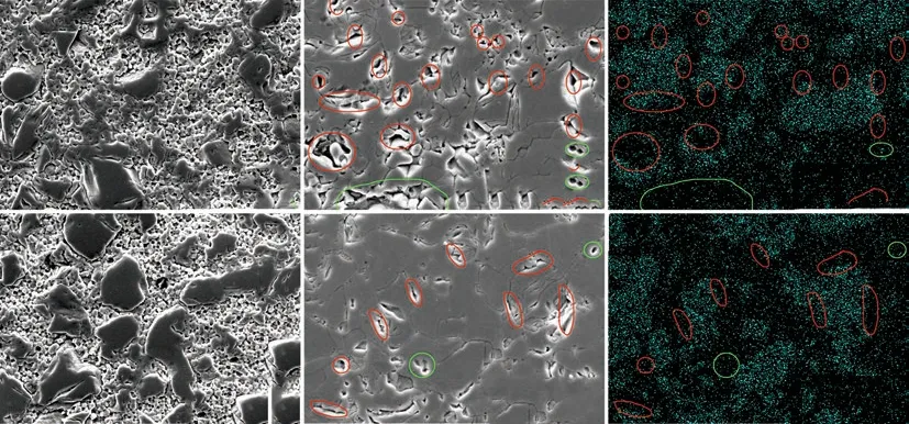
Fig.5 Polished surfaces of the ZrB2@ZrO2 composites with 30wt% ZrO2 sintered at (a)1 500, (d) 1 600, (b) 1 700, and (e) 1 800 ℃, where(c) and (f) correspond to the element B distributions of (b) and (e). The red circle is the pore near the B-enriched zone, and the green circle is the pore away from the B area
3.3 Effect of coating content on densification behavior
3.3.1 XRD analysis of ZrB2@ZrO2composite
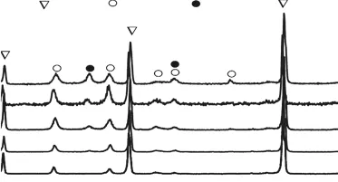
Fig.6 XRD patterns of the ZrB2@ZrO2 composites sintered at 1700 ℃ with the reaction time of 2, 4, 8, 12, and 24 h. The corresponding ZrO2 contents were calculated to be 13wt%,16wt%, 20wt%, 25wt%, and 30wt%, respectively
Fig.6 shows the XRD patterns of the ZrB2@ZrO2composites sintered at 1 700 ℃ via the coated powders with different reaction time. The phases include ZrB2,m-ZrO2and a small amount oft-ZrO2. The whole ZrO2content is calculated to be 13wt%-30wt% according to the RIR method. And both them-ZrO2andt-ZrO2gradually increase with the whole coating content.
3.3.2 Relative density of ZrB2@ZrO2composite
Fig.7 shows the relative densities of of the ZrB2@ZrO2composites with various ZrO2content sintered at 1 700 ℃. For comparison, the relative densities of uncoated ones are listed. As can be seen, the RD of the coated samples is above 90%, while that of uncoated ones is below 80%. Such results highlight the excellent sintering performance of coated powder. With the increased ZrO2content, the RD of the coated samples firstly increases and then decreases. The maximum value of RD reaches about 97% when the ZrO2content is 20wt%-25wt%.
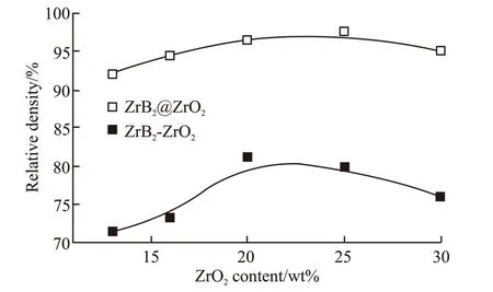
Fig.7 The relative density of of the ZrB2@ZrO2 composites with various ZrO2 content, sintered at 1 700 ℃ for 10 min under a pressure of 40 MPa. The uncoated ones are listed for comparison
3.3.3 Microstruce of ZrB2@ZrO2composite
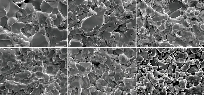
Fig.8 Fracture surfaces of the ZrB2@ZrO2 composites with (a) 13wt%, (b) 16wt%, (c) 20wt%, (d) 25wt%, (e) 30wt% ZrO2 sintered at 1 700 ℃ for 10 min under a pressure of 40 MPa. The uncoated one (f) with 30wt% ZrO2 is listed for comparison
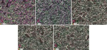
Fig.9 EDS maps for the ZrB2@ZrO2 composites with (a) 13wt%, (b) 16wt%, (c) 20wt%, (d) 25wt%, and (e) 30wt% ZrO2 sintered at 1 700 ℃ where the pink is the element B and the green is the element O
Fig.8 shows the fracture morphologies of the ZrB2@ZrO2composites with different ZrO2contents sintered at 1 700 ℃. Compared with the porous microstructure of the uncoated sample (Fig.8(f)), the coated samples show the dense structure. The transgranular fracture and intergranular fracture exist simultaneously.The ZrO2enriched areas with irregular shape mainly shows the intergranular fracture.
Fig.9 shows the EDS maps of the polished surface of ZrB2@ZrO2composites with different ZrO2contents sintered at 1 700 ℃. The pink is the element B represented the ZrB2and the green is the element O represented the ZrO2. When the ZrO2content is 13wt%,the ZrB2has a continuous distribution. When the ZrO2content is 16wt%, the pink area (ZrB2) decreases and the continuous network structure remains. However,when the ZrO2content rises to 20wt%, the network structure of ZrB2is replaced with an island structure.With the further increased ZrO2content, the structure changes little.
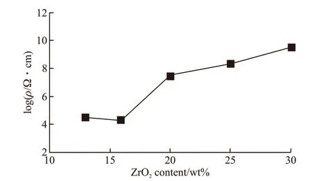
Fig.10 Volume electrical resistivities of the ZrB2@ZrO2 composites with various ZrO2 contents sintered at 1 700 ℃
Fig.10 shows the volume electrical resistivity of the ZrB2@ZrO2composites with various ZrO2contents sintered at 1 700 ℃. As can be seen, the resistivity is lower than 105Ω cm when the ZrO2content is 13wt%-16wt%. When coated with 20wt% ZrO2, the resistivity increases sharply to 108Ω·cm. With further increase of ZrO2content, the volume resistivity increased slowly.The phenomenon of resistivity mutating at a critical content is its percolation behavior. It reflects the evolution of the three-dimensional conductive network (ZrB2)from connection to interrupt in the structure. The result is consistent with the analysis of EDS maps (Fig.9).The minimum coating content for the interrupted network structure of ZrB2and the formation of the island structure of ZrO2is 20wt%.
3.4 Densification mechanism
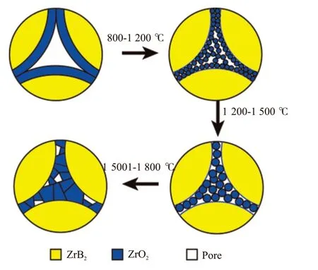
Fig.11 Schematic diagram for the densification mechanism of the ZrB2@ZrO2 composites

Fig.12 Hardness(a) and Fracture toughness(b) of the ZrB2@ZrO2 composites with various ZrO2 contents sintered at 1 700 ℃. The uncoated ones are listed for comparison
According to the analysis of the shrinkage curve and the evolution of microstructure of the ZrB2@ZrO2composite, the schematic diagram of the densification mechanism is shown in Fig.11. The sintering process can be divided into four stages: (I) When the temperature rises to 800 ℃, the powder coating gradually dehydrates and crystallizes. The rearrangement starts among the ZrO2particles and ZrB2particles. (II)When the temperature is 800-1 200 ℃, most of the volume shrinkage is completed and the RD reaches above 90%. The main processes include the enrichment and sintering of the ZrO2particles in the boundary and triangular regions between the micron ZrB2particles under high temperature and mechanical pressure. The sub-micron scale ZrO2makes it high surface activity and contributes to the formation and expansion of the sintering neck of ZrO2grains. It corresponds to the sharp shrinkage of ZrO2in this temperature range[18].(III) When the temperature is 1 200-1 500 ℃, the RD changes little. The main sintering process is the slow grain growth of ZrO2. (IV) When the temperature is above 1 500 ℃, the main sintering process occurs between ZrB2and ZrO2particles. The RD reaches above 95%. Meanwhile, the ZrO2particle coarsening from several microns to 10 microns or more occurs,which corresponds to the oversintering of ZrO2[21,22]at this high temperature.
The in-situ formed coating of the powder hinders the direct contacts of micron ZrB2particles which is difficult to be sintered. The isolation effect of the coating changes the main sintering process. It is transformed into the sintering of the ZrO2coating, followed by sintering between ZrB2and ZrO2. The former could be completed below 1 500 ℃ due to its high sintering activity, and the latter needs even high sintering temperature.
When the ZrO2coating content is below 20wt%,the dehydration and shrinkage of the coating lead to the incomplete coverage of ZrB2powder. There exists a small amount of direct contacts of ZrB2particles,which slightly increases the sintering difficulty and forms the network structure of ZrB2. The direct contact area is much smaller than that of the uncoated sample,resulting in a high RD (>90%). With the increase of ZrO2content, the direct contact area of ZrB2decreases gradually, and the isolation effect of coating layer is enhanced. Thus, the sintering difficulty is reduced. When the sintering content is 20wt%, the direct contact area of zirconium boride is minimized. And the maximum isolation effect of the coating reaches. Further increasing the coating content, the negative effects of zirconia in oversintering state on densification should not be ignored. As a whole, the ZrB2@ZrO2powder with 20wt%ZrO2has the best sintering performance.
3.5 Mechanical properties
Fig.12(a) shows the Vickers hardness of the ZrB2@ZrO2composites with various ZrO2content sintered at 1 700 ℃. The uncoated samples are listed for comparison. As can be seen, the Vickers hardness is 600-800 HV. It increases first and then decrease with the increase of coating content, which is similar to the trend of the RD (Fig.7). Both the coated and uncoated samples do not achieve the full density. The porosity,as the third phase, is the most important factor affecting the hardness of composites. Thus, the uncoated composite with high porosity shows an even poor hardness and the trend is similar.
Fig.12(b) shows the fracture toughness (KIC) of the above samples. It changes little with the content.TheKICvalue is 2.5-3.5 MPa·m1/2, slightly higher than that of pure ZrB2ceramics (about 2.4 MPa·m1/2)[23].However, compared with the uncoated samples, theKICof the coated samples is significantly improved. This indicates that the dense structure contributes to improving the fracture toughness of the composite.
4 Conclusions
The ZrB2@ZrO2powders with full coverage and controllable coating content prepared by in-situ passivation reaction have excellent sintering performance.The relative density could reach 95% when sintered at 1 700 ℃.
With the increase of ZrO2coating content, the structure of the sintered body changes from ZrB2continuous network structure to island structure. When the content is 20%, an island structure is formed. Increasing the ZrO2content further causes the overheating of ZrO2. Thus, the best sintering performance reaches when the coating content is 20wt%.
杂志排行
Journal of Wuhan University of Technology(Materials Science Edition)的其它文章
- Comparative Case Study on Adhesion of Three Common Sizing Agents to Cotton and Polyester Yarns
- Effect of Outer Carbon Layer Thickness of Carboncovered N-doped Hollow Carbon Nanospheres on Its Electrocatalytic Performance
- Ceramification of Composites of MgO-Al2O3-SiO2/Boron Phenolic Resin with Different Calcine Time
- Natural Fresh Proteins Directed Hierarchically Porous Nitrogen-doped TiO2 as with High Performance as Photocatalyts and Electrode Materials
- Dynamic Adsorption of Toluene on Hierarchical Porous Carbons with Varying Pore Structure
- Self-propagating High-temperature Synthesis of Sm and Zr Co-doped Gd2Ti2O7 Pyrochlore Ceramics as Nuclear Waste Forms
