Numerical and experimental studies on solidification of AZ80 magnesium alloy under out-of-phase pulsed magnetic field
2021-03-10WenhaoDuanSiqiYinWenhongLiuZhongZhaoKunHuPingWangJianzhongCuiZhiqiangZhang
Wenhao Duan,Siqi Yin,Wenhong Liu,Zhong Zhao,Kun Hu,Ping Wang,Jianzhong Cui,Zhiqiang Zhang,∗
aKey Lab of Electromagnetic Processing of Materials,Ministry of Education,Northeastern University,Shenyang 110819,Liaoning,PR China
b College of Materials Science and Engineering,Northeastern University,Shenyang 110819,Liaoning,PR China
c College of Information Science and Engineering,Northeastern University,Shenyang 110819,Liaoning,PR China
d State Key Laboratory of Rolling and Automation,Northeastern University,Shenyang 110819,Liaoning,PR China
Received 27 August 2019;received in revised form 10 March 2020;accepted 15 March 2020
Available online 10 July 2020
Abstract For obtaining the finer grains of magnesium alloy,a novel combined pulsed magnetic field with different initial phases,also called out-ofphase pulsed magnetic field(OPPMF),was applied to study the solidification structure of AZ80 magnesium alloy.The numerical simulation was simultaneously conducted to investigate the refinement mechanisms.The experimental results showed that the macrostructure could be effectively refined by applying external magnetic field.Meanwhile,finer grains were obtained with the higher current intensity.However,the increase of current intensity could only refine the grains to about 0.5mm.Furthermore,compared to a single pulsed magnetic field(PMF)and alternating series of OPPMF(Connection II),a finer structure was observed when the consecutive series of OPPMF(Connection I)was imposed.In contrast with a single PMF and Connection II,the numerical results showed that the greater axial Lorentz force was obtained under the Connection I,generating the stronger forced flow in the melt.It is believed that abundant nuclei could detach from the mold wall and move faster into the interior melt due to the stronger forced flow;besides,the lower superheat and greater temperature uniformity in bulk melt were realized,accounting for the finest structures under the Connection I.
Keywords:Out-of-phase pulsed magnetic field;Magnesium alloy;Grain refinement;Numerical simulation;Forced flow.
1.Introduction
Recently,considerable attentions have been focused on magnesium alloys due to their low density and wide application prospects in aerospace,automotive and other fields[1–6],which can be a good substitute to steels and aluminum alloys[7].With ascending demands of commercial application,mechanical properties,manufacture performances and corrosion resistance of Mg alloys need to be further optimized[8–10].Alloying with rare earth elements has attracted a lot of attentions because it can improve the comprehensive properties of Mg alloys[11,12].However,high content of rare earth elements greatly increases the cost of Mg alloys[13],therefore,it is necessary to develop other methods.Grain refinement,as one of the most effective ways to improve alloy performances,can improve both strength and plasticity of alloys[14,15],so does corrosion resistance[2].Application of electromagnetic stirring is an ideal method to obtain finer structures,because it is effortless to control and no contamination.Magnetic fields including alternating magnetic stirring(AMF)[16,17],electromagnetic vibration[18,19],permanent magnetic stirring[20-22]and rotational magnetic stirring[23,24]all have been proved to refine solidified structure[25].
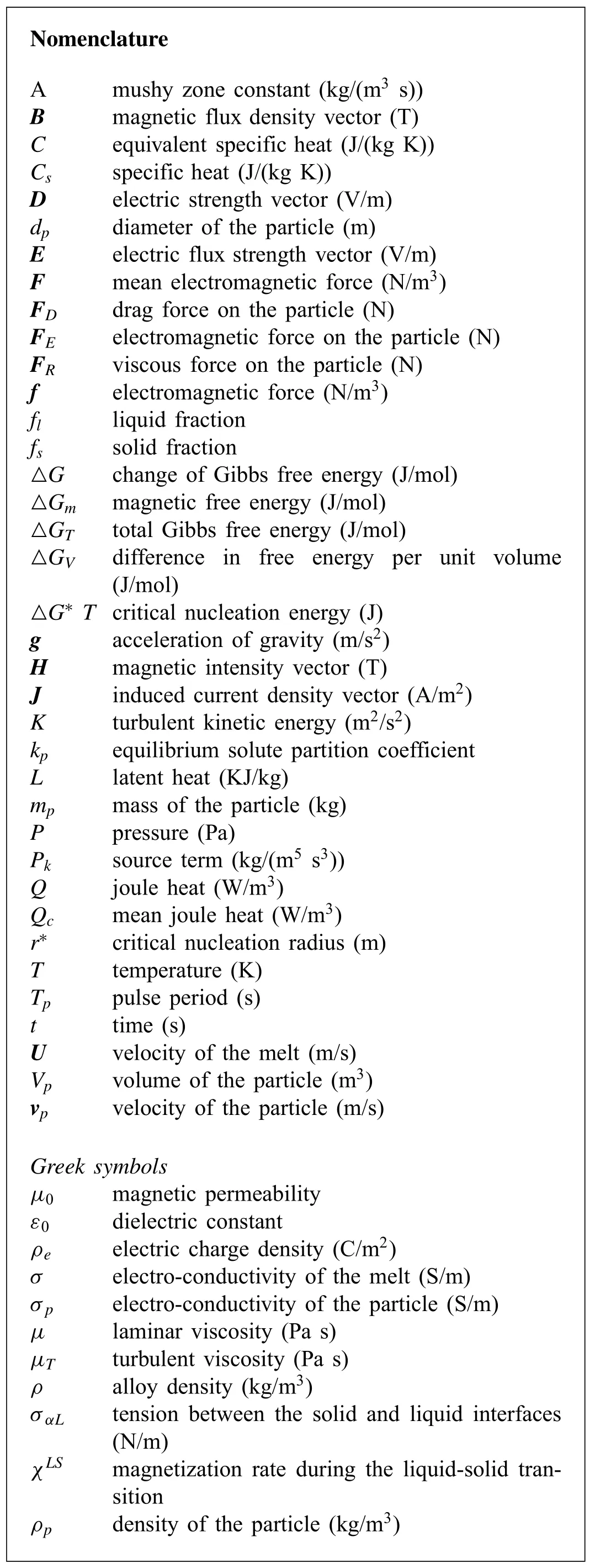
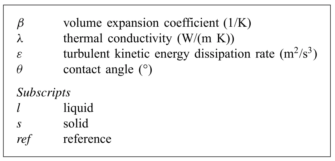
Recently,electric current pulse(ECP)and pulsed magnetic field(PMF)have gained increasing attentions because of their large energy capacity,instantaneous high magnetic intensity,and simple equipment[26].Ma et al.[27]considered that PMF caused both convection and vibration in the melt.Liao et al.[28]found that ECP could make the crystal nucleus fall off from the mold wall and drift in the liquid,giving rise to the multiplication of nuclei and grain refinement.Also,the skin effect of ECP could promote this refining effect.Li et al.[29]simultaneously applied two parallel electrodes excited with pulsed current in the solidification of pure aluminum,and found that a better refining effect was realized as compared to the up-down electrodes.However,the pollution taken by electrode cannot be ignored.Therefore,PMF and pulsed magnetic oscillation(PMO)were developed to improve the solidified structure.Gong et al.[30]considered that nuclei were easily fallen off from the mold and more evenly distributed throughout the melt under the action of PMO.As there is a great difference on the electrical resistivity between solid and liquid,Li et al.[31]revealed that free flowing nuclei could be driven faster than surrounding liquid and this uncoupled motion contributed to the finer structure.Liotti et al.[32]found that the intensified inter-dendritic liquid flow caused by the external field of PMF could produce a sudden change of solute concentration at liquid-solid interface,which was helpful for the dendrite re-melting and obtaining many nuclei.Meanwhile,other refinement mechanisms,such as promoting nucleation[33],dendrite fragmentation[34],cavities activation mechanism,[35,36]also have been proposed.
In fact,most of refinement mechanisms are highly associated with forced flow and vibration of the melt under the action of PMF or PMO.However,compared with AMF,when PMF is applied,the intensity of convection is fairly smaller in the case of identical current due to the intermission of pulsed current[37].According to the theory of electromagnetic field,larger capacity pulsed power is necessary so as to achieve higher forced flow.However,enhancing pulsed power is not a desirable method since it requires strict equipment and is hard to control.Considering the limitations of using a single PMF,combined magnetic fields have become a promising method on the solidification process recently.Hua et al.[38]and Haghayeghi and Kapranos[39]have combined the PMF with the static magnetic field and apply them to the solidification process,and found that a more refined structure was obtained as compared to a single PMF.Yu and Li[40]applied an AMF on the solidification of ZK60 alloys.In their experimental equipment,three winding coils arranged up and down have been loaded with a three-phase alternating current.
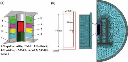
Fig.1.(a)Schematic of the casting step.(b)Geometry of the model and finite element mesh used in the simulation.(For interpretation of the references to color in this figure legend,the reader is referred to the web version of this article.).
Enlightened by Yu et al.,we have adopted the multi winding coils arranged up and down in the research and the pulsed currents possessing different initial phases were stimulated into the coils.Compared with AMF or single PMF,it can not only guarantee the melt vibration,but also extend the stirring time.This new method is named as out-of-phase pulsed magnetic field(OPPMF).
In this research,the solidification structure of AZ80 magnesium alloy under OPPMF has been investigated and compared with that under a single PMF and no magnetic field(NMF).Meanwhile,the numerical study of the solidification process was included to better understand the refinement mechanisms under OPPMF.
2.Numerical models
2.1.Model apparatus
Fig.1(a)shows the schematic of apparatus.It can be seen that four winding coils have been arranged up and down and each of the winding coil is 25 turns.The melt is located in the centerline of the crystallizer and the half-height of it is close to the central horizontal line of the four coils.The simulation model is simplified to a 2D axisymmetric model in consideration of the symmetry of the apparatus.Fig.1(b)shows the dimension of the mold and the finite element mesh used in the model.The dimension of the ingot isΦ50mm×length 80mm.
2.2.Mathematical models
The coupling of fluid flow and solidification process needs to settle the equations of mass,momentum and energy distribution in the melt.A single domain of volume-averaged porous model whose fluidity depends on the value of permeability[37]was used to calculate the continuity and momentum conservation equations.The treatments of velocity damping[41]and latent heat[42]were included in the equations.
The influence of magnetic field on the solidification process is mainly realized by the electromagnetic force and the joule heat.In reality,both of the electromagnetic force and the joule heat are varying with time,which makes the calculation very difficult.Therefore,the mean electromagnetic force F and the joule heat Qcwere introduced in the research,which are given in Table 1.
The tracing of the nucleus was calculated by the Lagrangian approach and the movement of the nucleus can be solved through the Newton’s second law.Additional force influenced by magnetic field,buoyancy force and viscous force were also considered,the Schiller-Naumann law was used to describe the drag force[43].
The detailed governing equations are listed in Table 1.
2.3.Initial boundaries
In the experimental research,the graphite crucible and the melt were heated and kept warm at 998K together.Thus,the initial temperature of the melt and the mold was set as 998K.The free surface and outer surfaces of the mold were set as a Robin-type thermal boundary,which is given in Eq.(1),theheat transfer coefficients of them are listed in Table 2.
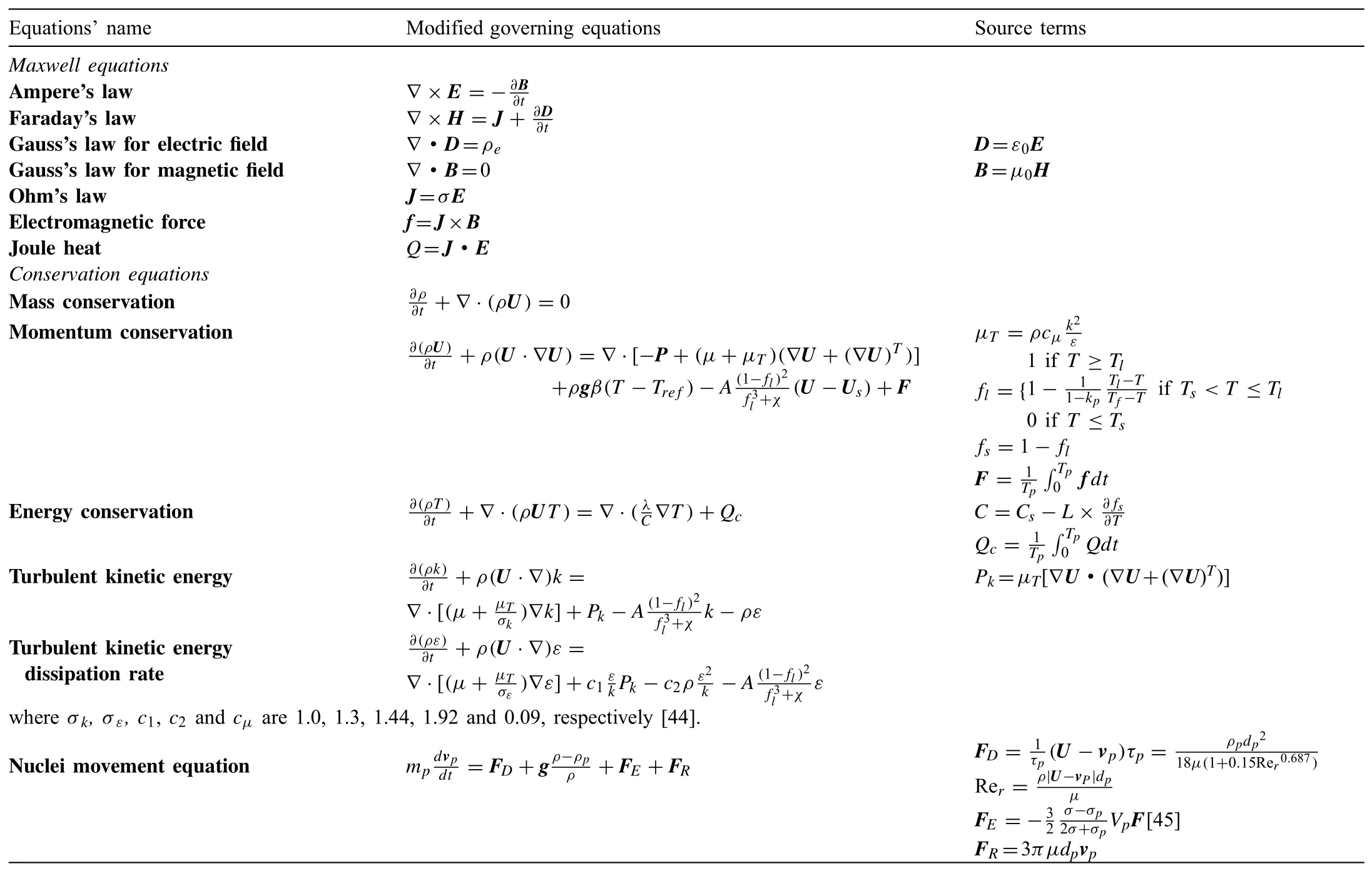
Table 1Summarized governing equations.

The initial melt velocity was set as zero.In this research,a single PMF was realized by loading the current 1(Fig.2(d))into four coils which have been connected in series(Fig.2(a)),while the OPPMF with two connection methods were used.As can be seen in Fig.2(b)and(c),One is to connect coils 1 and 2 in series and load current 1,coils 3 and 4 in series and load current 2,which is defined as consecutive series(Connection I).The other is to connect coils 1 and 3 in series and load current 1,coils 2 and 4 in series and load current 2,which is defined as alternating series(Connection II).The two pulsed currents with different initial phases were measured by the oscilloscope and smoothed in order to improve the convergence of the calculation,which are shown in Fig.2(d).The measured current intensity was 100 A,the frequency was 20Hz and the duty cycle was 20%.The phase difference of 90° is defined as that the time lag between the two pulsed currents is exactly half of the pulsed width.During the simulation,the smoothed two pulsed currents were written and defined in the software,then loaded into the corresponding coils in the form of boundary conditions.
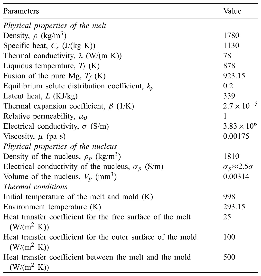
Table 2Physical properties and thermal conditions used in the simulation.
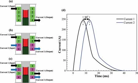
Fig.2.The three connection ways of the coils and the loaded current intensities:(a)a single PMF case;(b)OPPMF with Connection I case;(c)OPPMF with Connection II case;(d)pulsed current waveforms with different initial phases.(For interpretation of the references to color in this figure legend,the reader is referred to the web version of this article.).
2.4.Numerical strategies
The COMSOL Multiphysics software based on the finite element method has been implemented to solve the coupled problems between electromagnetic field,fluid field and thermal field.The total mesh cells used in the melt and the mold were 1785,while those in the whole model were 6946.The actual solidification under external field is a complex process involving multiple-fields interactions,some weak couplings and minor factors are necessary to be simplified and neglected appropriately so as to improve the convergence and save the computation time,which are given as following:
(1)The melt was regarded as the incompressible newton fluid.
(2)The influence of the melt flow on the magnetic field was neglected,because the Magnetic Reynolds number Rm<<1[42].
(3)The latent heat and the equilibrium solute distribution coefficient were treated as the constant value[46].
(4)The effect of solute distribution on the flow and temperature was not considered since the ingot size was small and the solute segregation was not serious.
(5)The casting system was cylindrical symmetry and thus could be rendered as a 2D axisymmetric model for modelling.
2.5.Model validation
In order to verify the model used in the simulation,the measurement of temperature at half height of the melt center was conducted every 10s under the conventional solidification condition without magnetic field by inserting the thermocouple into the melt,and a comparison between the measured temperature and the simulated temperature at the same position is given in Fig.3.It can be seen that the simulated results match well with the measured results,indicating that the model used in the research is viable.The discrepancy may be attributed to the constant heat transfer coefficient between the mold and the melt used in the simulation,which is much higher than the real heat transfer coefficient in the later solidification stage during the actual solidification process.Therefore,the lower temperature is generated in the simulated results.
3.Experimental methods
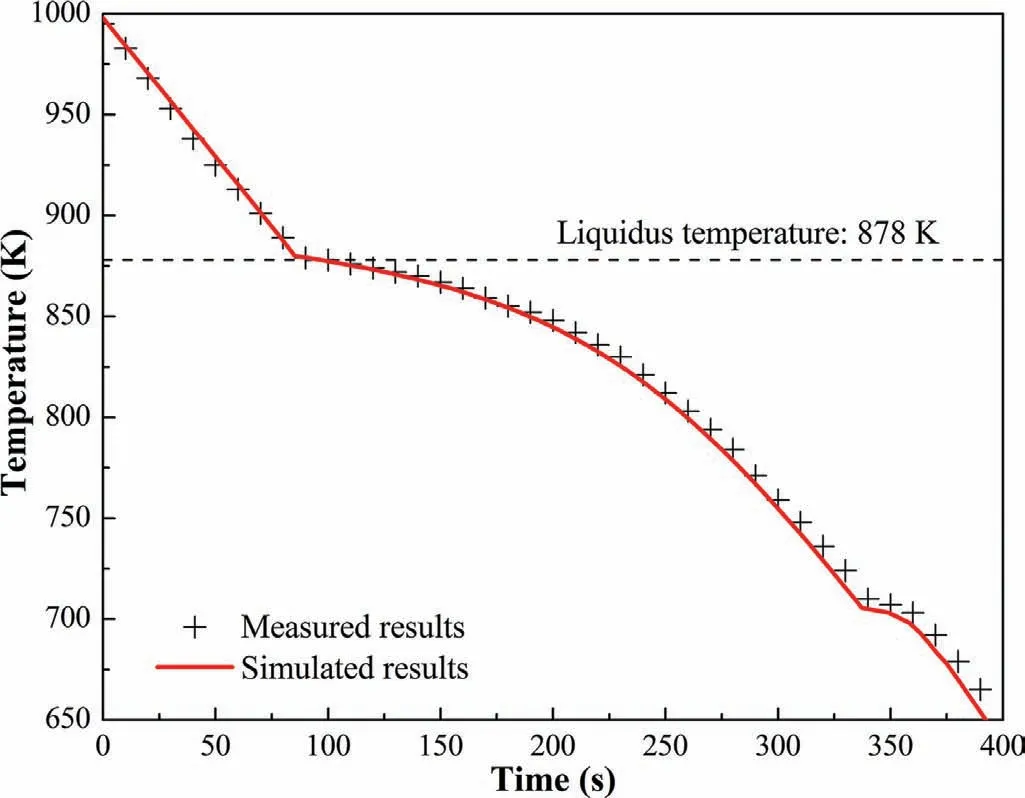
Fig.3.Comparison between the measured temperature variation and the simulated temperature variation at half height of the melt center.(For interpretation of the references to color in this figure legend,the reader is referred to the web version of this article.).
Prior to smelting,the AZ80 magnesium alloy billet which was sprinkled with Sulphur powder on the top surface has been placed on a graphite crucible and covered with a graphite lid to prevent the oxidation loss.After being held for 50min at 998K in a resistance furnace,it was then placed in the crystallizer as shown in Fig.1(a)and the electromagnetic field was switched on at the same time and sustained for 11min.Finally,the ingot was removed from the crystallizer and cooled at room temperature.To make a comparison,one ingot was untreated with magnetic field.The remaining nine ingots were respectively treated with current intensities of 50 A,100 A and 150 A under a single PMF,Connection I and Connection II.The as-cast specimens were cut along the radial section at the half height of the sample.After being grinded with sandpaper until to 5000# and mechanically polished,the specimens were etched with the etchant consisting of 70mL alcohol,10mL glacial acetic acid,10mL distilled water and 6g picric acid.Finally,the solidified macrostructures in the cross-section and longitudinal section of the samples were analyzed by a stereomicroscope SZX 16.The average grain size was estimated by performing the measurement in the same sample five times using the linear intercept method.
4.Simulation and experimental results
In the numerical study,the current intensity with 100 A is discussed in this section.Also,the simulation of conventional solidification without the magnetic field was carried out in order to make a comparison.
4.1.Distribution of Lorentz force and Joule heat
The distributions of mean Lorentz force and Joule heat are shown in Fig.4.The Lorentz force and Joule heat decrease as the distance from the melt surface increases due to the skin effect.In the case of a single PMF,the Lorentz force shows almost the horizontal pressure force in the melt,while it is only at the top and bottom of the melt that Lorentz force respectively points obliquely downward and obliquely upward,into the melt.However,when the Connection I is applied.The Lorentz force points downward to the melt at a certain angle,and the maximum magnitude of the mean Lorentz force is almost the same as that with a single PMF.As for the case of the Connection II,the distribution of Lorentz force is quite similar to the case of a single PMF,except that the direction of Lorentz force is obliquely downward both at the top and bottom of the melt.Also,the maximum magnitude of mean Lorentz force is obviously lower than that with a single PMF.The mean Joule heat is mainly distributed at the side surface of the melt as shown in Fig.4(d–f),which is similar to the distribution of Lorentz force.The maximum value of mean Joule heat under the two cases of OPPMF is almost identical,but significantly smaller in comparison with a single PMF.
4.2.Distribution of flow field
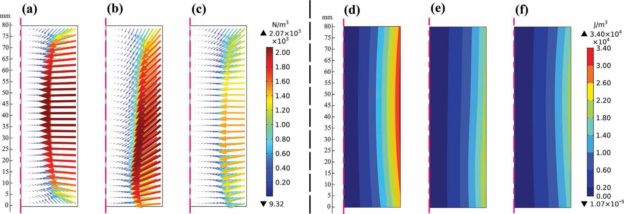
Fig.4.Comparison of mean Lorentz force and Joule heat:(a),(b)and(c)show the mean Lorentz force distribution under a single PMF,the Connection I and the Connection II cases,respectively;(d),(e)and(f)show the mean Joule heat distribution under a single PMF,the Connection I and the Connection II cases,respectively.(For interpretation of the references to color in this figure legend,the reader is referred to the web version of this article.).
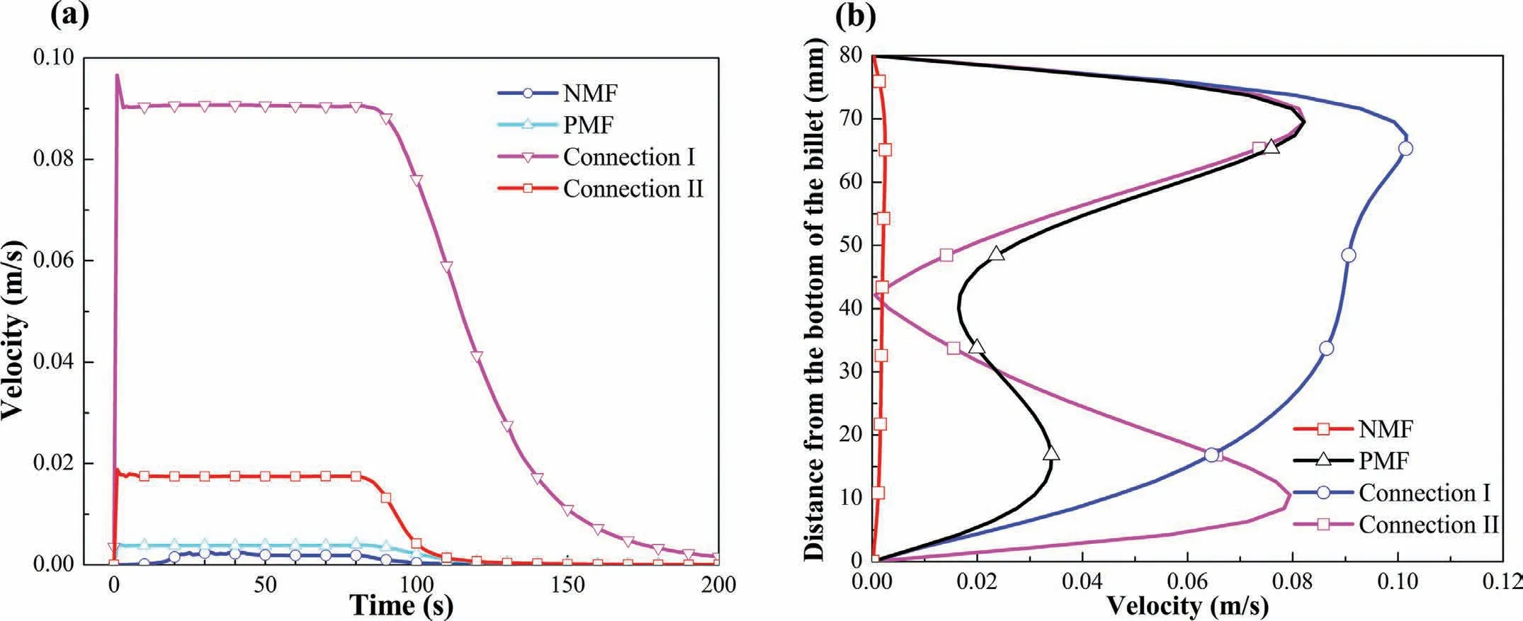
Fig.5.Distribution of velocity magnitude under different cases:(a)variation of velocity magnitude with time at point A(Fig.1(b));(b)distribution of velocity magnitude from the bottom of the melt to the top near the side surface of the melt at the initial solidification stage.(For interpretation of the references to color in this figure legend,the reader is referred to the web version of this article.).
Previous study[37]has shown that the melt flow stabilized after certain periods,oscillating in a certain range with the pulsed current varies.Subsequently,the melt velocity would gradually damp to zero as the solidification process continues.The similar results were obtained in our numerical simulation as shown in Fig.5(a).However,the averaged velocity is presented without reflecting the oscillation in our research due to the treatment of mean Lorentz force.It can be seen from the velocity variation at point A(Fig.1(b))that the stable velocity decreases in the order from the Connection I,Connection II,a single PMF to NMF.Fig.5(b)displays the velocity distribution near the side surface of the melt from the bottom of the melt to the top during the initial solidification stage.In the case of OPPMF with Connection I,most areas suffer the stronger forced flow and the maximum velocity reaches 0.1m/s.Whereas,both of a single PMF and the Connection II display the weaker and non-uniform forced flow near the mold wall.The change of velocity distribution near the mold wall indicates that there are remarkable differences in melt flow patterns corresponding to various forms of magnetic field.
Fig.6 shows the flow fields when the velocity reaches stable(see Fig.5(a))under various forms of magnetic fields as far as the right half in the meridian plane.As shown in Fig.6(b),the flow pattern is composed of a upper clockwise vortex and a underlying counterclockwise vortex under a single PMF case,and the intensity of these two vortices is almost the same.The obtained results are similar to those reported by Chen and Shen[37]and Ma et al.[27].This is because the melt surface is subjected to the mean Lorentz force that is almost perpendicular to the surface and points internally under a single PMF(Fig.4(a)),resulting in the metal liquid that originally flows downward along the melt surface under the condition of NMF moving toward the center of the melt,and then moving upward or downward along the center axis of the melt respectively,thus forming the upper and lower two vortices in the melt.In the Connection I case(Fig.6(c)),a large clockwise vortex that has many similarities in common as NMF case(Fig.6(a))is generated,but the stronger forced flow is achieved not only in the internal melt,but also in the melt surface.This can be ascribed to the that the mean Lorentz force shows the characteristic of pointing obliquely downward into the interior melt(Fig.4(b)),which promotes downward flow of the metal liquid along the melt surface.Subsequently,the metal liquid moves upward along the center axis under the action of rebound of the bottom mold wall.Finally,a larger and stronger vortex forms in the melt.For the case of Connection II(Fig.6(d)),both of the upper large vortex and lower small vortex have clockwise direction,and the strength of the upper vortex is in similar to that shown in a single PMF condition.Furthermore,there exists a larger vortex that surrounds the two vortices,which has many characteristics in common with that shown in Connection I condition.Because the distribution of mean Lorentz force is quite similar to that in a single PMF condition,but also shows some similar characteristics with the Connection I(Fig.4(c)).
It is considered that in electromagnetic casting,an electromagnetic force produced in the melt includes two parts[47]:

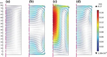
Fig.6.Averaged Flow patterns at the stable stage under different cases:(a)NMF;(b)a single PMF;(c)Connection I;(d)Connection II.(For interpretation of the references to color in this figure legend,the reader is referred to the web version of this article.).
the first part on the right-hand side is the rotational component which contributes to the forced flow in the melt,while the second part is irrotational component to realize the soft contact between the melt and the mold.As for the cylindrical casting,the rotational component is regarded as the axial component of Lorentz force and the irrotational component is the radial component of Lorentz force.Combining with the previous analysis of Lorentz force distribution,with the Connection I,the larger axial component of Lorentz force is generated.Therefore,it is not hard to explain why the Connection I case possesses obviously stronger forced flow than a single PMF under the same maximum magnitude of the mean Lorentz force.Meanwhile,when the Connection II is imposed,an increase in the proportion of the axial component of Lorentz force near the top of the melt is produced as can be seen in Fig.4(c),which can provide the stronger stirring intensity if the magnitude of mean Lorentz force is the same as a single PMF.Consequently,the upper vortex similar to the one in a single PMF condition is generated even with the lower magnitude of mean Lorentz force.
4.3.Temperature distribution
Fig.7 shows the temperature distributions at the beginning of the solidification and after solidified for 30s in four cases.It can be seen that with the weak thermal convection,the dramatically uneven temperature distribution from the inner melt to the surface is generated under the NMF.Inversely,the temperature is more uniform distributed in bulk melt with the application of magnetic field.At the beginning of the solidification shown in Fig.7(a–d),unlike the NMF case where amount of the heat is gathered in the center of the melt,lots of heat accumulates at the bottom of the melt in the case of a single PMF.When the Connection I and the Connection II are imposed,the hot melt is located at the upper melt.Using the magnetic field can remarkably reduce the melt temperature due to the forced flow,indicating that the superheat of the melt is greatly decreased.Also,with the application of Connection I and Connection II,especially the Connection I,the maximum temperature is lower than a single PMF,demonstrating that OPPMF is more conducive to reduce the melt superheat at the initial solidification stage.After solidified for 30s(Fig.7(e-h)),which is believed to concern with the growth stage of the crystal,the minimum temperature under a single PMF is 869K,while,it is 867.65K for the Connection I and the Connection II cases.This can be ascribed to the larger Joule heat under a single PMF as shown in Fig.4(d-f).In addition,it is obvious that the solidification in the Connection I case is more synchronous in bulk melt.Furthermore,the areas with high temperature decrease greatly throughout the melt under the Connection I,while most of the melt possesses higher temperature in a single PMF and the Connection II cases.
4.4.Experimental results
The solidified macrostructures of cross section with respect to different current intensities under various magnetic fields are shown Fig.8.It can be seen that the macrostructures are composed of coarsely equiaxed grains under the NMF(0 A),and the average grain size is 1.85mm(with a standard deviation of 0.14mm)as can be seen in Fig.9.With the magnetic field,the solidified macrostructures are greatly refined.Also,it is clear that the grain size in the Connection I and the Connection II cases is smaller as compared to a single PMF case when the current intensity is 50 A.In order to clearly reveal those variations,the average grain size is presented in Fig.9.When the current intensity increases from 50 A to 100 A,a remarkable reduction of the average grain size is occurred of all cases.However,with the current intensity further increasing to 150 A,the reduction of grain size is not so obvious.Also,it seems that the average grain size can only be refined to about 0.5mm and is very close in three cases when the current is 150 A.Among three cases,the average grain size of the Connection I case is the finest,regardless how the current intensity changes.As the current intensity increases to 100 A and 150 A,compared to the Connection II,a single PMF is more prone to obtain the finer average grain size.
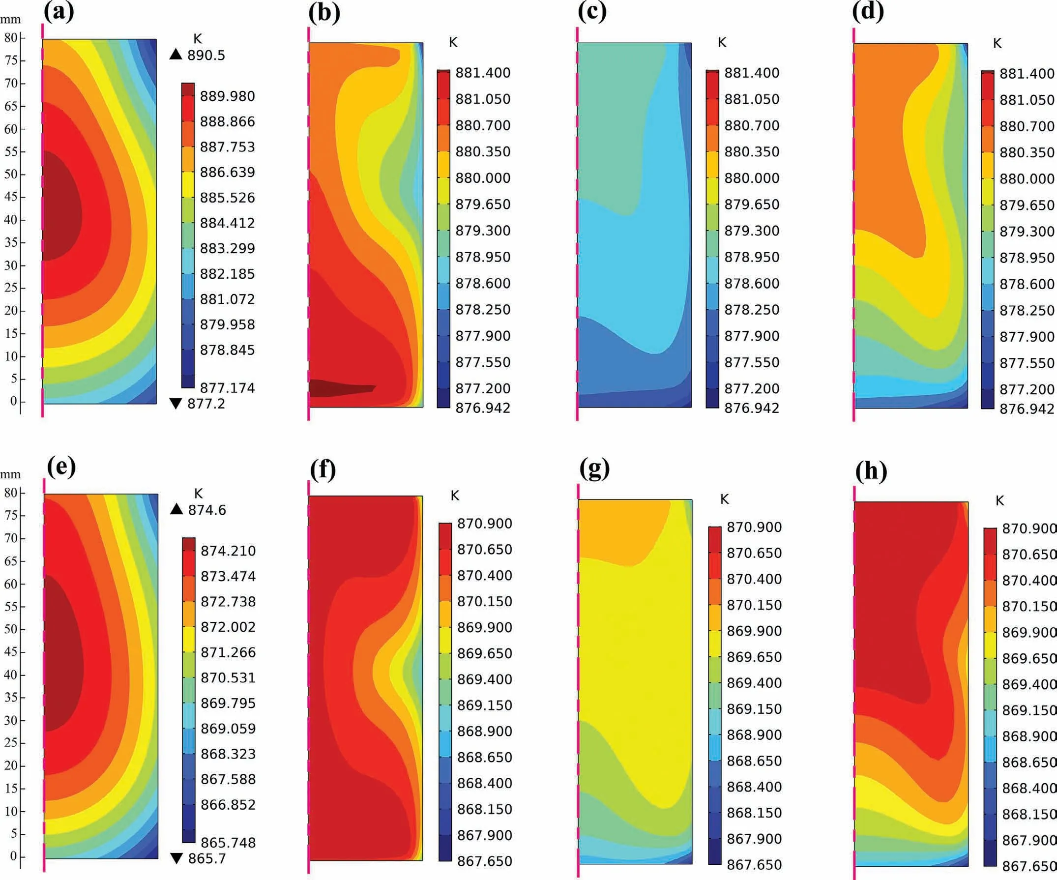
Fig.7.Comparison of the temperature distribution in the melt:(a),(b),(c)and(d)display the temperature distributions at the beginning of the solidification under the NMF(78s),a single PMF(78s),the Connection I(81s)and the Connection II(78s),respectively;(e),(f),(g)and(h)display the temperature distributions after solidified for 30s from the beginning of the solidification under the NMF(108s),a single PMF(108s),the Connection I(111s)and the Connection II(108s),respectively.(For interpretation of the references to color in this figure legend,the reader is referred to the web version of this article.).
5.Discussion
5.1.Effects of magnetic fields on grain refinement
To make clear the refining mechanisms,a cylindrical sieve(mesh 100)made of stainless steel was placed in the graphite crucible to prevent the nucleus from passing through the sieve.The sieve was quickly inserted into the melt after the sieve and alloy have been placed together in a furnace preheated to 998K and kept warm for 40 min.Then,they were kept warm together for another 10 min to make assurance that the total warm time was 50 min.Finally,they were placed in the crystallizer and the magnetic field was initiated simultaneously.The current intensity is 100 A.
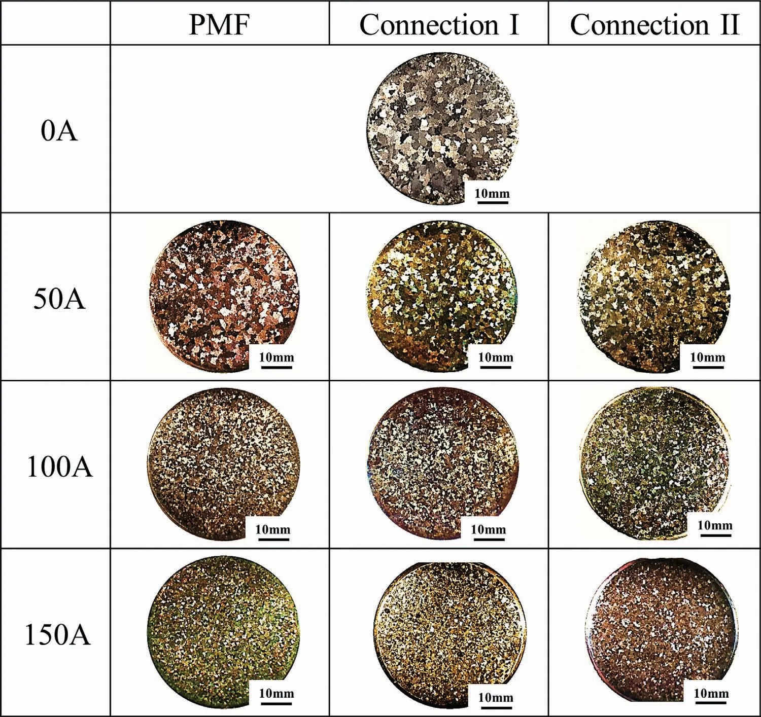
Fig.8.Solidified macrostructures of the cross section of the ingot under different current intensities and magnetic fields.(For interpretation of the references to color in this figure legend,the reader is referred to the web version of this article.).
As can be seen from the longitudinal section of billet in Fig.10,the solidified macrostructures in and out of the sieve both have the coarse grains and show little differences under the NMF(Fig.10(a)),indicating that there is no obvious increase in the number of nucleation cores in bulk melt.However,with the Connection I,the macrostructures of no sieve are composed of uniform and fine structures throughout the whole section(Fig.10(b)),while the macrostructures inside the sieve are coarser than that outside the sieve when a sieve is placed in the melt(Fig.10(c)).The same results are obtained with the application of a single PMF and Connection II(Fig.10(d)and(e)).Therefore,it is concluded that the refining mechanism under the three cases is primarily resulted from the increase of the nuclei transported from the mold wall,rather than the nucleation of the melt itself due to the existence of inclusions,or the dendrite fragmentation.
With the application of magnetic field,Li et al.[33]and Choi et al.[48]considered that the variation of Gibbs free energy produced by magnetic field would contribute to the refinement.When the magnetic field is imposed,the magnetic free energy△Gmand the change of Gibbs free energy△G can be written as:

where△GVis the difference in free energy per unit volume between the solid and liquid phases,χLSis the magnetization rate during the liquid-solid transition.As far as the heterogeneous nucleation,the schematic diagram of heterogeneous nucleation is shown in Fig.11(a).Therefore,the total Gibbs free energy is described as:

whereσαLis the tension between the solid and liquid interface.Thus,the energy required for the critical nucleation and the critical radius of nucleation are obtained as following:
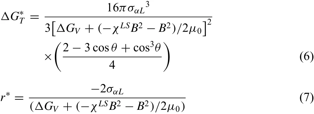
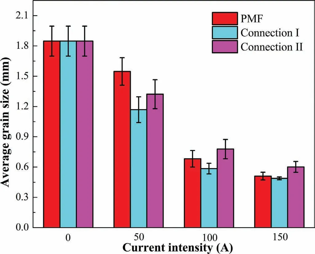
Fig.9.Variation of the average grain sizes under different current intensities and magnetic fields.(For interpretation of the references to color in this figure legend,the reader is referred to the web version of this article.).
Since the△GVis negative,from the Eqs.(6)and(7),it can be inferred that the critical nucleation energy△G∗T and the critical nucleation radius r∗decrease with applying the magnetic field.With a magnetic field,Li et al.[33]and Zhang et al.[49]considered that the nucleation could occur in large quantities even with a lower undercooling.Therefore,plenty of nuclei will generate near the mold wall,increasing the total number of nucleation particles.Also,as can be seen from Fig.11(b),with the same current intensity,the distribution of averaged magnetic flux density is almost identical regardless of which magnetic field is used,indicating that the critical nucleation energy and the critical nucleation radius are independent of the forms of magnetic field.
Actually,from the beginning of nuclei detachment to the transportation of nuclei,and finally the survival and growth of these nuclei in bulk melt,all these factors will have an important effect on the final solidified structures.This paragraph focuses on the detachment or scour of nucleus from the mold wall under different magnetic fields and current intensities.Under the action of the magnetic field,the detachment of nucleus from the mold is not only highly concerned with the melt convection near the mold wall,but also with the electromagnetic force.Cheng et al.[50]derived a criterion between the radial electromagnetic force and the detachment of nucleus,which is given in Eq.(8):
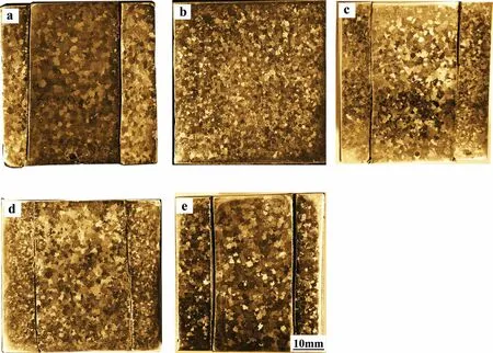
Fig.10.Longitudinal section of the macrostructures under different cases:(a)NMF with a sieve;(b)Connection I without sieve;(c)Connection I with a sieve;(d)PMF with a sieve;(e)Connection II with a sieve.(For interpretation of the references to color in this figure legend,the reader is referred to the web version of this article.).
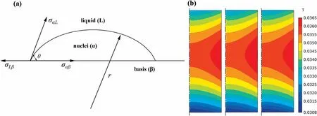
Fig.11.(a)Schematic of the heterogeneous nucleation.(b)Averaged magnetic flux density with a current of 100 A under three cases(from left to right are a single PMF,Connection I and Connection II).(For interpretation of the references to color in this figure legend,the reader is referred to the web version of this article.).
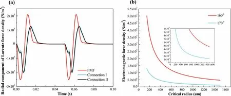
Fig.12.(a)Radial component of the Lorentz force varies with time when the current intensity is 150 A under different cases.(b)The maximum radial Lorentz force density required under different critical radius.(For interpretation of the references to color in this figure legend,the reader is referred to the web version of this article.).
where P0is the atmosphere pressure,g is the gravitational acceleration,h is the distance from the liquid surface to the nucleus,r is the radius of nucleus as illustrated in Fig.11(a),σsandσlare the electrical conductivity of solid phase and liquid phase,respectively.Fig.12(b)reveals the relationship between the peak of radial Lorentz force and the critical radius at point A,which is calculated according to the Eq.(8).It can be seen in Fig.12(b)that the peak of radial electromagnetic force required to separate the nucleus with a radius of 1.5mm from the mold wall is about 106N/m3under the poor wetting condition.However,the peak of radial component of Lorentz force density can only reach 2.5×10⁵N/m3at point A among three cases when the current intensity is 150 A(Fig.12(a)),only a quarter of the critical value.Therefore,the nucleus separation produced by the Lorentz force can be neglected since the actual critical nucleus radius is much less than 1.5mm.
As a consequence,the forced flow should be the main factor that contributes to the drop of nuclei.In the flow field,the drag force brought by the fluid will be imposed on the nuclei formed on the mold,thus promoting those nuclei to drift into the internal melt.With the Connection I,the stronger and uniform melt convection along the mold wall(shown in Fig.5(b))indicates that more nuclei formed on the mold can be fallen off and drifted into the melt,increasing the total number of freely floating nucleation particles.With a single PMF and the Connection II,only a small number of nuclei can be washed off near part of the mold wall due to the weaker and uneven convective velocity near the mold wall.
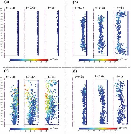
Fig.13.Movement of the nuclei with time under different cases:(a)NMF;(b)PMF;(c)Connection I;(d)Connection II.(For interpretation of the references to color in this figure legend,the reader is referred to the web version of this article.).
As a large number of nuclei form and fall off near the mold wall,the movement of these nuclei to the internal melt will play a significant role in subsequent process.Fig.13 shows the simulation results of the movement trail of nuclei corresponding to different magnetic fields when the current intensity is 100 A.Some simplifications are listed as following:(1)nucleus is treated as the sphere;(2)the melting,agglomeration,growth,and shrinkage of nucleus are not considered;(3)The force between nuclei is not taken into account;(4)Nuclei are uniformly released from the side wall of the mold,and it is assumed that the number of nuclei is the same under various magnetic fields.(5)Supposing that nuclei release at a certain time in the early stage of the solidification,and this moment is defined as the initial moment during the simulation of the nuclei movement.From the results shown in Fig.13(a),with the NMF case,almost all the nuclei are fixed in the mold wall,no nuclei could move into the interior melt,accounting for the formation of coarse grains throughout the whole section as shown in Fig.10(a).When the magnetic field is imposed,although some nuclei are yet fixed on the mold,a considerable number of nuclei can still move into the internal melt in a short time,particularly in the Connection I case(Fig.13(c)).With the Connection I,the nuclei not only move faster,but also distribute more uniform.However,with a single PMF(Fig.13(b))and the Connection II(Fig.13(d)),the nuclei are gathered in a line and move into the melt at a slower rate.

Fig.14.Movement of the nuclei with different current intensities under the connection I:(a)50 A;(b)100A;(c)150 A.(For interpretation of the references to color in this figure legend,the reader is referred to the web version of this article.).
During the solidification,the detachment and transportation of nuclei caused by forced flow,in fact,occur at the early solidification stage,which was revealed by Morando et al.[51].In the case of higher movement velocity of the nuclei,the nuclei detached from the mold can leave the mold at a faster rate and avoid accumulation near the mold wall,thus reducing the thickness of the chill layer.A thicker chill layer not only makes it hard for generating new nuclei,but also makes it difficult for nuclei to pass through it,which is not conducive to the grain refinement.It was just as Wei et al.[21]have proposed that with the departure of many nuclei from mold wall,new nuclei would form again near the mold wall and then drift into the interior melt.Therefore,in order to avoid the accumulation of a large number of nuclei near the mold wall,faster movement of nuclei is required so as to promote the generation of new nuclei near the mold wall and increase the total number of nuclei in the melt.Furthermore,the dispersive motion of nuclei means that nuclei are not easily to combine with each other,thereby avoiding a sharp reduction in the total number of nuclei and ultimately improving the nucleation rate.Consequently,the finer grains are obtained in the Connection I case.
In reality,a large number of nuclei will melt and even disappear during the movement due to the high degree of superheat inside the melt,and a completely melted nucleus can no longer become a nucleation particle.Therefore,reducing the melt superheat at the initial solidification stage is helpful for the preservation of the nuclei.With the magnetic field,especially the Connection I(Fig.7(a-d)),the superheat inside the melt is dramatically decreased,indicating that more nuclei may survive in the melt.As the solidification process progresses,a growing number of nuclei formed in bulk melt and the distances between nuclei become short.Nuclei will then grow rather than continue to serve as nucleation sites in the later solidification stage.With a uniform temperature distribution,the synchronous solidification of the melt and the suppression of rapid growth of nuclei are promoted,facilitating the generation of fine equiaxed grains[52].Therefore,from the results shown in Fig.7(e-h),it is no wonder why the finest and uniform grains are obtained under the Connection I.
5.2.Effect of the current intensity
An increase in the current intensity could not only enhance the magnetic free energy,thus increasing the nucleation rate,but also strengthen the intensity of forced flow,which helps scour the nuclei from the mold wall and force these nuclei into the internal melt.Fig.14 shows the movement of nuclei with different current intensities under the connection I.As can be seen from the figure when the current intensity is low(50 A),though some nuclei could detach from the mold wall,they move quite slow as compared to 100 A and 150 A cases.Thus,as the new nuclei form near the mold wall,a growing number of nuclei will accumulate together near the mold,thickening the chill layer and ultimately restraining the nuclei movement and formation of new nuclei.According to the Maxwell’s equations,when the current intensity increases to 100 A,the Lorentz force will be four times greater than that with 50 A case.Therefore,the noticeably stronger melt convection will generate,which consequently promotes the detachment and transport of nuclei.The significantly increase of total number nuclei,the faster movement and uniform distribution of the detached nuclei account for the phenomenon that the obvious reduction of grain size is realized when the current intensity increases from 50 A to 100 A.As the current intensity increases further to 150 A,the number of detached nuclei does not change distinctly,only shows a little bit faster moving velocity than those under 100 A.So the average grain size decreases little as the current intensity increases further to 150 A.
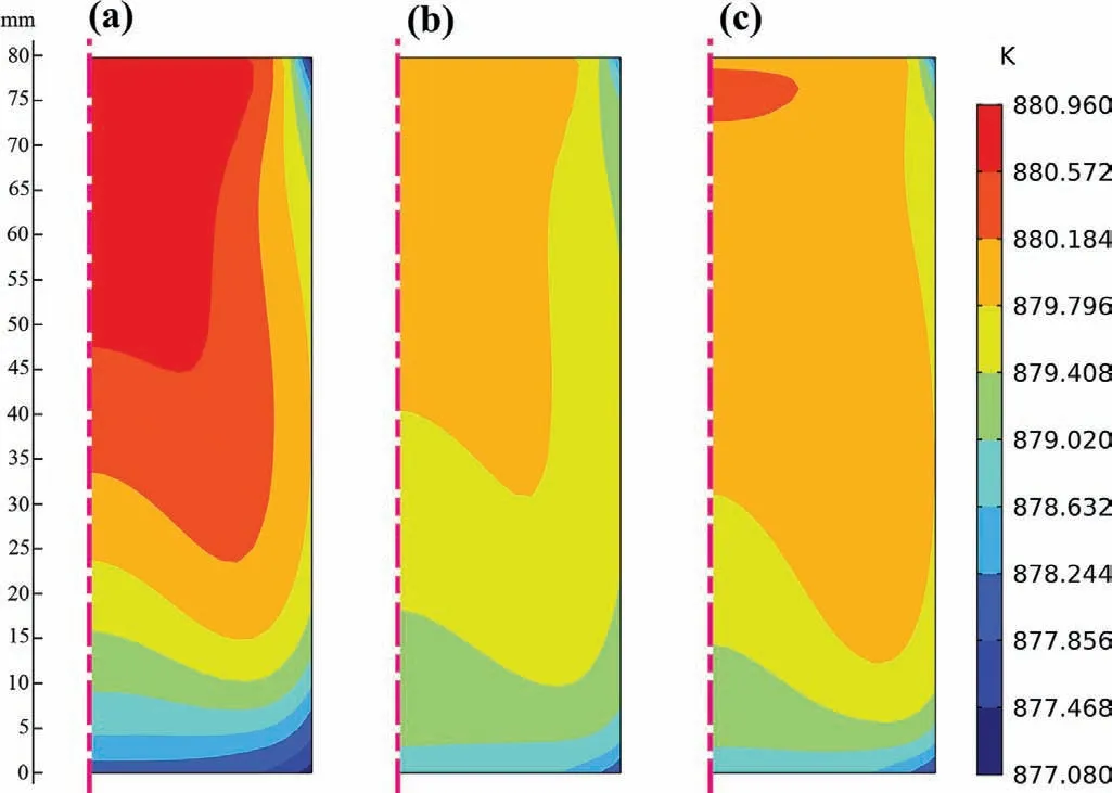
Fig.15.Temperature distributions with different current intensities at the beginning of the solidification under the Connection I:(a)50 A;(b)100 A;(c)150 A.(For interpretation of the references to color in this figure legend,the reader is referred to the web version of this article.).
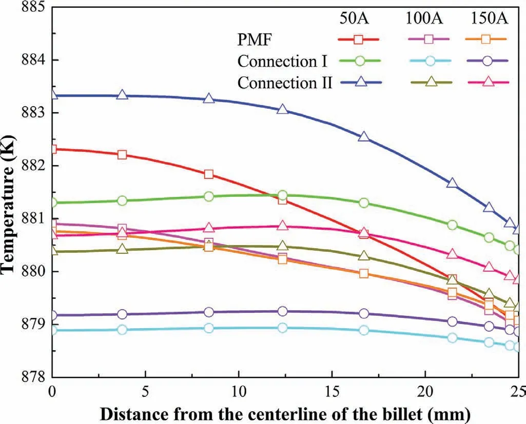
Fig.16.Temperature distribution from the melt surface to the center at half height of the melt at the beginning of the solidification.(For interpretation of the references to color in this figure legend,the reader is referred to the web version of this article.).
In addition,lower temperature is generated as the current intensity increases from 50 A to 100 A as can be seen in Figs.15 and 16,this can promote a large number of the nucleation in the melt because of the higher undercooling degree.Furthermore,temperature uniformity is also enhanced at the same time,which is beneficial to the preservation of nuclei transported from the mold wall.All of these factors contribute to the evident refinement of macrostructures as compared to 50 A case.However,when the current intensity increases further to 150 A,there is no remarkable variation of temperature uniformity in all the cases except for a tiny rise in temperature value.This may be that the ingot size in our experiment is small,the intensity of heat convection will not continue to rise indefinitely and a certain limit will generate.In addition,the larger Joule heat can heat the melt under the higher current intensity.The rise of temperature at higher current intensity reduces the degree of undercooling,which consequently lowers the nucleation rate.These should be the reasons why the average grain size decreases less as the current increases from 100 A to 150 A and can only be refined to about 0.5mm.With a single PMF,the larger joule heat is generated(see Fig.4(d)),which heats the melt.Therefore,the minimum temperature is increased in the melt(Fig.7),especially at a higher current intensity,indicating that the solidification time is extended.The increase of solidification time means that the stirring time is also increased simultaneously.This account for the result of obtaining the finer equiaxed structures with a single PMF as compared to the Connection II case when the current intensity is high.
6.Conclusions
The multi winding coils loaded into pulsed currents with different initial phases were used to generate out-of-phase pulsed magnetic field(OPPMF)and study on the solidification structures of AZ80 magnesium alloy under OPPMF was implemented.In addition,the numerical method was carried out to make clear the solidification process.The obtained results are summarized as follows:
•With the consecutive series of OPPMF(Connection I),the higher axial component of Lorentz force is achieved as compared to a single pulsed magnetic field(PMF)and the alternating series of OPPMF(Connection II),resulting in the strongest forced flow in the melt under the identical current intensity.
•Both a single PMF and two forms of OPPMF can refine the solidified structures of AZ80 magnesium alloy.It is believed that the grain refinement is resulted from the increase of total nucleation particles in the whole melt,which come from the mold wall due to the forced flow.
•With the Connection I,more nuclei can be detached from the mold wall and enter the interior melt faster under the stronger forced flow.Also,the lower superheat and higher temperature uniformity in bulk melt are obtained simultaneously.These factors account for the finest grain size under the Connection I as compared to a single PMF and the Connection II.
•For AZ80 magnesium alloy ingot with a diameter of 50mm,the average grain size of as-cast structure decreases significantly when the current intensity increases from 50 A to 100 A.However,with further increasing the current intensity to 150 A,the reduction of average grain size is not so obvious and the structures can only be refined to about 0.5mm.
•As compared to a single PMF,the OPPMF with Connection I is probably a more promising method for improving the solidification structures and subsequent the billet quality.Also,it has good prospects for industrial application,such as semi-continuous casting,etc.
Declaration of Competing Interest
None
Acknowledgments
This work was supported by the National Key Research and Development Program of China(Grant No.2016YFB0301101),the National Natural Science Foundation of China(Grant No.51971054),the Fundamental Research Funds for the Central Universities(Grant No.N180904006 and N2009006).
杂志排行
Journal of Magnesium and Alloys的其它文章
- Recent developments and applications on high-performance cast magnesium rare-earth alloys
- Surface characterization and corrosion behavior of calcium phosphate(Ca-P)base composite layer on Mg and its alloys using plasma electrolytic oxidation(PEO):A review
- Towards developing Mg alloys with simultaneously improved strength and corrosion resistance via RE alloying
- Magnesium matrix composite reinforced by nanoparticles–A review
- The design of Co3S4@MXene heterostructure as sulfur host to promote the electrochemical kinetics for reversible magnesium-sulfur batteries
- A new die-cast magnesium alloy for applications at higher elevated temperatures of 200–300°C
