First results of negative ion extraction with Cs for CRAFT prototype negative beam source
2021-03-01YahongXIE谢亚红ChundongHU胡纯栋JianglongWEI韦江龙YongjianXU许永建CaichaoJIANG蒋才超YumingGU顾玉明YuanzheZHAO赵远哲LizhenLIANG梁立振andYuanlaiXIE谢远来
Yahong XIE (谢亚红) , Chundong HU (胡纯栋), Jianglong WEI (韦江龙),Yongjian XU (许永建), Caichao JIANG (蒋才超), Yuming GU (顾玉明),Yuanzhe ZHAO(赵远哲),Lizhen LIANG(梁立振) and Yuanlai XIE(谢远来)
Institute of Plasma Physics, Chinese Academy of Sciences, Hefei 230031, People’s Republic of China
Abstract In order to understand the physics and pre-study the engineering issues for radio frequency(RF)negative beam source,a prototype source with a single driver and three-electrode accelerator was developed.Recently, the beam source was tested on the RF source test facility with RF plasma generation, negative ion production and extraction.A magnetic filter system and a Cs injection system were employed to enhance the negative ion production.As a result,a long pulse of 105 s negative ion beam with current density of 153 A m−2 was repeatedly extracted successfully.The source pressure is 0.6 Pa and the ratio of co-extracted electron and negative ion current is around 0.3.The details of design and experimental results of beam source were shown in this letter.
Keywords: neutral beam injector, RF ion source, negative ion source, long pulse, Cs feeding
1.Introduction
The Comprehensive Research Facility for Fusion Technology(CRAFT) is a large scientific device that is preferentially deployed for the construction of major national science and technology infrastructures.It is a bridge between the experimental fusion research device and the fusion commercial reactor.A negative beam source based neutral beam injector(NNBI)is one of the most important devices to be developed for fusion plasma heating and current driven.The target of NNBI system is to have the ability to deliver a powerful beam with beam energy of 400 keV, beam power of 2 MW and beam duration of 100 s.It is best to operate the radio frequency (RF) beam source with a long pulse due to its long lifetime and no tungsten contamination compared with the hot cathode arc source[1-3].The RF based negative beam source was employed for the CRAFT NNBI system, which was also the reference source for ITER-NNBI system [4, 5].In order to understand the physics and pre-study the engineering issues for RF negative beam source, a prototype source with single driver was developed [6].In last year, the RF source achieved long pulse discharge of 1000 s with RF power of 35 kW and shot pulse of 60 s with 80 kW on the RF ion source test bed [7-12], respectively.Recently, the RF beam source was tested with negative ion production and extraction with Cesium(Cs)injection.As a result,a long pulse of 105 s negative ion beam was achieved with extracted negative ion density of 153 A m−2.The details about the accelerator,magnetic filter, Cs injector and experimental results are presented in this letter.
When Grandma Lizzie came to our apartment, I rushed to her, demanding an answer. She said, Spinal4 meningits, and told how my father had been stricken with the disease when he was two. As he approached school age, his hearing diminished until there was none, not even the memory of sound.
They arrive exactly at 8:00 a.m. to take her home, but she has been ready since before seven. She has taken a shower -- not an easy task lying down on a shower stretcher. She isn’t allowed to sit up yet without her body brace1, but regardless, here she is, clean and freshly scrubbed and ever so anxious to go home. It has been two-and-a-half months since she has seen her home -- two-and-a-half months since the car accident. It doesn’t matter that she is going home in a wheelchair or that her legs don’t work. All she knows is that she is going home, and home will make everything okay. Even Dorothy says so: “Oh, Auntie Em, there’s no place like home!” It’s her favorite movie.
2.Experimental setup

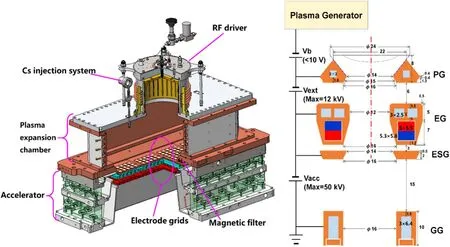
Figure 1.Schematic of RF negative beam source.

Figure 2.Design of magnetic filter (left: position of permanent magnets, right: distribution of magnetic field in beam source).
The schematic of RF beam source and negative ion accelerator is shown in figure 1.It consists of a plasma driver, a plasma expansion chamber(EC)and an accelerator with three electrodes.The RF driver is 120 mm in height with a diameter of 220 mm, which contains a ceramic insulator, RF coil,Faraday shield (FS) [13] and a back plate of driver.The plasma generated in the RF driver will expand in the EC with dimension of 650 mm(length) × 260 mm(width) × 190 mm(height).The hydrogen negative ion beam extraction and acceleration system is designed based on the ITER NBI ion source[14,15].It comprises three grids:the plasma grid(PG)where the diameter of aperture is 14 mm, the extraction grid(EG)where the co-extracted electrons are deflected out of the beam by embedded permanent magnets, and the ground grid(GG)[16],which can be seen in figure 1.Each grid is divided into four segments and each segment has 5 × 6 apertures.Two molecular pumps with pump speed of 2600 l s−1was installed for vacuum pumping.Due to the weak pumping ability, only two segments of grids were installed.So, the total extraction area is 92 cm2.
For your wife? she asked. She spoke38 with what he recognized as a genteel Kentucky accent, in this city of old money where such distinctions mattered. After just six months in town, he already knew this. It s all right, Jean, she went on, turning back to the clerk. Go on and take him first. This poor man must feel lost and awkward, in here with all the lace.
In order to decrease the destruction of negative ions and the co-extracted electrons,and enhance the negative hydrogen ions yield, the magnetic filter and Cs feeding system were designed and installed on the beam source.
The prototype RF beam source for CRAFT NNBI system was developed and tested with Cs injection on the RF beam source test facility.The characteristics of beam source with Cs conditioning were studied.As a result, stable long pulses of 105 s negative ion extraction was achieved.The extracted ion density is 153 A m−2and the ratio ofje/jexis around 0.3.This is the first time to release the Cs into the beam source.It lays a good foundation of the research and design of negative ion source for CRAFT NNBI system.
(2) The acceleration high voltage(-50 kV@50 A)will be used for beam extraction and beam optics studies.

Figure 3.Schematic of electrical measurement of RF negative beam source.

Figure 4.Change of extracted ion current density and ratio of co-extracted election current and negative ion current with Cs conditioning.
(3) The prototype beam source will be equipped with full scale accelerator.
The temperature is also important for the negative ion production with Cs feeding.For the prototype beam source,the temperature of source body was actively controlled around 40°C.The PG is without cooling and it was heated by the RF plasma with long pulse, normally between 150 °C to 200 °C.In order to keep the hot PG, the discharge interval was controlled around two minutes.
Quite a few months went by with just flirting and such things then I felt I had to do something or say something, I feelings that I hadn t felt before and I started not paying attention to things that were more important. All I thought about was him. His friends were always trying to hook5 us up and get us together but we never quite got there. I had had enough I decided6 to tell him what I felt and when I did I got what I expected. He had feelings for me too but was scared so thought that we shouldn t go out. I agreed but I wasn t amused with him response. I felt better that I had got those feelings off of my chest but something still wasn t right.
3.Experimental results
The-50 kV high voltage power supply for beam acceleration was occupied by other system.In order to conditioning the beam source,the extractor grid power supplyVHV(-16 kV&20 A) was used both for beam extraction and acceleration with a divider resistance, as shown in figure 3.The voltage applied on PG is the output of extractor grid power supply,the voltage applied on EG can be adjusted by the connecting point on the divider resistance, which can be changed from 10%to 90%ofVHV.During the experiment,50%ofVHVwas applied between PG and EG for beam extraction when Cs conditioning (i.e.8 kV).When testing the high current beam extraction ability, 70% ofVHVwas applied between PG and EG (i.e.11 kV).The co-extracted electrons are deflected by permanent magnetic field to EG, and it is measured asIEG.The extracted negative ions will go through the GG and be collected by a Faraday plate.The total extracted negative ion current is measured asI(H−).During the experiment,the high voltage applied on PG and EG cannot be well matched;thus,ion beam optics was not considered.

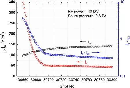
Figure 5.Conditioning of Cs injection with RF power of 40 kW.

Figure 6.Waveform of long pulse of 105 s negative ion extraction with ion density of 153 A m−2.
When the Cs evaporated and released into the source,it will cover the source surface,especially the surface of PG,where the negative ions produced.With two weeks conditioning, the extracted negative ions current density increased from 40 to 155 A m−2, and the ratio of co-extracted electrons current and extracted ions current decreased from 10 to 0.25, as shown in figure 4.Normally,there were 200-250 shots each day.When the source does not work, the pumping system keeps gas pumping and the temperature of Cs feeding system decreases to 60 degrees(close to the feeding valve).It also can be seen thatje/jexis very high at the beginning of each day,and then decreases to below 1.This means that the source was well conditioned.
The effect of Cs conditioning on the parameters of beam source in one day was shown in figure 5.The RF power is 40 kW and the source pressure is 0.6 Pa.It can be seen that the extracted negative ion density increased from 96 to 141 A m−2,and reached the saturation point.The co-extracted electron density decreased from 350 to 50 A m−2in 40 shots,and the ratio of co-extracted electron to negative ion densityje/jexdecreased from 4 to 0.3,which is a typical effect of Cs on the surface production of H−.
In the future,the negative ion extraction and acceleration with large area will be tested on the RF beam source test facility.Several things will be considered as follows.
4.Conclusions and future plans
When I woke up that morning all I wanted to do was walk. It was winter my favorite season. This walk would change my life forever and I would remember for years to come. On that one special walk is where I meet the love of my life and lose my love. I remember it like it was yesterday.
During the experiment,it also be found that the RF plasma tends to unstable with high RF power (i.e.50 kW) when too much Cs was released into the plasma chamber.The Cs feeding rate is also an important issue and it will be studied soon.
The long pulse operation of negative ion extraction was also tested during the experiment.Considering that the maximum pump speed is only 5200 l s−1,most of holes in PG were blocked and only ten holes were left.As a result,long pulses of 105 s with RF power of 47 kW was achieved,which is shown in figure 6.It can be seen that the extracted ion current density increased from 148 to 153 A m−2in ten seconds and almost maintained no changes with ajexof 153 A m−2.The ratio ofje/jexis around 0.3 during beam extraction.The temperature of PG was increased around 25 degrees during long pulse.The long pulse beam extracted was repeated with eight shots continuously and each shot was much stable.
(1) A cryopump with large pump speed (more than 20 000 l s−1) will be installed in the RF beam source test facility.
(4) The PG temperature will be actively controlled for negative ion production.
Due to the narrow extraction size,the magnetic filter field was generated by permanent magnets [17, 18].Two rows of magnets, made of Sm2Co17with a core remanence of 1.0 T,are embedded on both sides of the flange at 47 mm above the PG, as shown in figure 2.The distance between two rows of magnets is 210 mm.The size of each permanent magnet is 120 mm (length) × 40 mm (width) × 10 mm (height).The figure shows that the magnetic field strength is close to 1 mT and 4 mT in the driver and before the PG, respectively.So,the ‘hot’ electron can be cooled-down to about 1 eV before the PG for minimizing the destruction of negative ions by electron collisions.More details can be seen in [12, 13].
The surface production is an effect way to generate negative hydrogen ions [19].The Cs injector system is designed based on other devices, such as BATMAN in IPP[20, 21].The Cs injector contains a Cs oven, transmission pipe, nozzle, gate valve and the thermocouples installed on the oven and pipes.Normally, the temperature of oven is controlled from 160°C to 240°C,and temperature of pipe is controlled from 200 °C to 260 °C.
Cake is the food of the rich, a symbol of feasting and plenty (Olderr 1986). In a land where bread is a precious food, cake would be a luxury beyond the children s imaginations. Sugar would also be a precious commodity in time of famine, especially appealing to children with their reputation for sweet tooths.
Next campaign of negative ion extraction and acceleration will start from October 2020, more results will be reported soon.
Acknowledgments
This work was supported by the Comprehensive Research Facility for Fusion Technology Program of China(No.2018-000052-73-01-001228).
ORCID iDs
Yahong XIE (谢亚红) https://orcid.org/0000-0002-1374-6544
Lizhen LIANG (梁立振) https://orcid.org/0000-0002-5744-5727
猜你喜欢
杂志排行
Plasma Science and Technology的其它文章
- Effects of packing particles on the partial discharge behavior and the electrical characterization of oxygen PBRs
- Energy dissipation and power deposition of electromagnetic waves in the plasma sheath
- Modification of exposure conditions by the magnetic field configuration in helicon antenna-excited helium plasma
- Theoretical model and experimental investigation optically triggered hollowcathode discharge formation
- Electron population properties with different energies in a helicon plasma source
- Design and performance study of a gas-Cherenkov detector with an off-axis parabolic reflector for inertial confinement fusion experiments
