电化学蚀刻钽箔制备高容量薄膜钽电解电容器
2021-02-02郭永富王日明于淑会初宝进
郭永富 王日明 于淑会 初宝进 孙 蓉
1(深圳先进电子材料国际创新研究院 深圳 518103)
2(中国科学院深圳先进技术研究院 深圳 518055)
3(中国科学技术大学纳米科学技术学院 苏州 215123)
4(中国科学技术大学 中国科学院能量转换材料重点实验室 合肥 230026)
1 Introduction

Fig. 1 Schematic illustration of (a) commercially available copper/dielectric layer/copper structured embedded capacitors, and (b) discrete thin film tantalum electrolytic capacitors图1 埋入式电容与分立式薄膜电解电容对比图: (a)商用铜/介电层/铜结构嵌入式电容器;(b)分立薄膜电解电容器
Electronic devices are continuously progressing toward miniaturization, which puts forward requirements on the size of constituent components. However, the limited surface area on an integrated circuit (IC) board creates a bottleneck on the development of high-density integrated circuits. To solve this problem, the idea of embedding components in the printed circuit board or IC substrate has been proposed[1-6]. Capacitors account for more than half of the passive components on an IC board, covering around 40% of the surface area[7]. Thus, the development of embedded capacitors with high energy density is of vital importance in the advancement of high-density IC[8-9]. However, the current commercial embedded capacitors with BaTiO3filled polymer as dielectric layer (Fig. 1(a)) can only afford very small capacitance of <0.1 nF/mm2, which hinders its wide application[10]. Due to its small specific capacitance value, the embedded capacitance of this ceramic/polymer composite material needs to occupy a large internal space in the circuit board when a large capacitance is needed. So an alternative strategy of using small-sized surface-mounted capacitors as embedded components (Fig. 1(b)) is put forward[11]. Among all types of capacitors, multilayered ceramic capacitors (MLCC) and Tantalum (Ta) electrolytic capacitors are playing dominant roles. Although MLCC has been widely used in electronic devices for its excellent high-voltage and high-frequency performance, MLCC severely suffers from the unstable capacitance with the fluctuation of voltage, temperature, and stress[12-16]. By comparison, Ta possesses a small thermal expansion coefficient[17], and tantalum pentoxide (Ta2O5) exhibits stable physical and chemical properties[18], which both contribute to the outstanding stability of Ta electrolytic capacitors, endowing Ta electrolytic capacitors great potential for their application as embedded capacitors in high-density IC system. Traditionally, the anode of Ta electrolytic capacitors is produced by the sintering of Ta powders[19-20], and the Ta electrolytic capacitor based on sintered Ta anode can provide a high specific capacitance of 0.1 μF~1 000 μF. However, the sintering process is complicated, and usually requires a highly vacuum condition under a temperature of over 1 200 °C[21-25]. The thickness of the obtained Ta electrolytic capacitor is usually beyond millimeter level, and such a huge thickness impedes its application as embedded capacitors, because the substrate where the passives are embedded has a limited thickness of several hundred micrometers.
Ta and Niobium (Nb) foils etchings have been reported, which involves the electrolyte containing hydrofluoric acid or its mixture[26], and the etched foils were used for catalysis. Similarly, isopropyl alcohol and n-butanol solutions of hydrofluoric acid were used to etch niobium foil, and a better etching effect was obtained[27-28]. Herein, we propose the utilization of invasive electrolyte (hydrofluoric acid n-butyl alcoholic solution) for the electrochemical etching of the Ta foils to fabricate anode for Ta electrolytic capacitors. The equation to calculate the capacitance of a parallel plate capacitor is listed as follows:

whereεis the permittivity of the dielectric (ε=25 for the anodic oxide of Ta),ε0=8.85×10⁻¹⁴F/cm is the permittivity of free space,Sis the surface area, anddis the dielectric thickness. Based on this equation, it is clear that large capacitance requires largeSwhendis fixed.
With the electrochemical etching approach, a thin Ta foil can be controllably etched, and the thin foil with enlarged surface area shows a specific capacitance as high as 74 nF/mm2with an oxidation voltage of 12 V when measured in 0.1 mol/L H2SO4. The etched Ta foils is then fabricated into electrolytic capacitors after the deposition of cathode layer, graphite layer, and silver paste[29]in sequence. The electrolytic capacitors based on electrochemically etched Ta foils demonstrate a stable capacitance of >30 nF/mm2over the frequency range of 100 Hz~1 MHz and a low leakage current of 2.7×10⁻⁶A. The electrolytic capacitor has a thickness of 75 μm, which is thin enough for their application as embedded capacitors.
2 Experimental
2.1 Materials
Tantalum foils (99.9% purity) with a thickness of 50 μm were purchased from Sigma-Aldrich, China. Phosphoric acid (H3PO4, ≥85wt%) and hydrofluoric acid (HF, ≥40wt%) were purchased from Sinopharm Chemical Reagent. n-butanol (AR, 99%) was purchased from Aladdin. Platinum electrodes were used as counter electrode for both Ta etching and oxidation process. A polytetrafluoroethylene electrolytic cell (Shanghai Honghe Sealing Material Co. LTD), with a volume of 50 mL, was used for etching.
2.2 Electrochemical etching of Ta foils
Hydrofluoric acid was diluted to 2 wt% with n-butanol, and was used as etching electrolyte. The tantalum foil was cut to an area of 5 mm×5 mm, the same size as the counter electrode. Tantalum foils were ultra-sonicated in 2-butanone for 10 min, followed by washing with ethanol and drying in oven at 80 ℃, and 20 mL etching electrolyte was added into an electrolytic cell. A series of samples were obtained by applying a pre-defined etching voltage (in the range of 20~80 V) at ambient temperature. The duration of etching time was 2~5 h. The electrochemically etched Ta foils were denoted as Ta-20V2H, Ta-40V2H, Ta-60V2H, Ta-80V2H, Ta-40V3H, Ta-40V4H, and Ta-40V5H, respectively, where the first two digits represented the applied voltage, i.e., 20 V, 40 V, 60 V, and 80 V, and the last digit represented etching hours, i.e., 2 hours, 3 hours, 4 hours, and 5 hours. During the etching process, the speed of the magnetic stirring was set as 800 r/min.
2.3 Oxidation (Ta2O5 formation)
The Ta foils were oxidized at a constant voltage of 12 V (formation voltage) for 3 h in 0.1 wt% H3PO4aqueous solution at 80 ℃.
2.4 Characterizations
The morphology of pristine and etched Ta foils was examined by field-emission scanning electric microscope (FE-SEM, FEI NovaNano SEM450). The surface elements of tantalum foil before etching, after etching and after oxidation were analyzed by X-ray photoelectron spectroscopy (XPS, Thermo Fisher EscaLab 250Xi). 3D Laser Scanning Microscope was used to analyze the surface of etched tantalum foil. Three 1 000 μm×1 000 μm areas were randomly selected for measurement, and the multi-line roughness Ra was measured.
2.5 Measurement of specific capacitance
The capacitance (C) was measured in 0.1 mol/L H2SO4by Precision Impedance Analyzer (Agilent 4294a) in the frequency range of 100 Hz~110 MHz as shown in Fig. 2 (a, c). The counter electrode material is platinum foil. The capacitor lead reserved on the tantalum anode is clamped with a platinum clip and the anode is immersed in sulfuric acid solution. The specific capacitance was acquired by dividing C tested at 100 Hz with the surface area of tantalum foils.

Fig. 2 Schematic illustration of (a) and (c) measuring capacitance of anode in 0.1 mol/L H2SO4, (b) and (d) measuring capacitance of tantalun capacitor图2 钽薄膜电容的湿法测试和器件测试过程: (a)、(c)钽电容阳极电容值的测量,(b)、(d)钽电容器件的测试
The oxidized Ta foils are also fabricated into Ta electrolytic capacitor by the deposition of Poly (2,3-dihydrothieno-1,4-dioxin), graphite layer, and silver paste. The leakage current was measured by an electrochemical workstation (Shanghai Chenhua Instrument Co., Ltd), and the testing process is shown in Fig. 2(b, d). The capacitive performance of Ta electrolytic capacitor is measured by Precision Impedance Analyzer (Agilent 4294A) in the frequency range of 100 Hz~110 MHz as shown in Fig. 2 (b, d).
3 Results and Discussions
3.1 Physical characterizations of electrochemically etched Ta foils
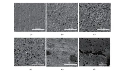
The surface of pristine Ta foil is not absolutely smooth and has certain roughness before etching (Fig. 3(a)). After electrochemical etching, the surface roughness is enhanced. SEM images (Fig. 3(b-d)) indicate that the surface roughness is linked with the applied voltage, and the surface is more roughened with higher applied voltage. Although the surface of Ta-80V2H appears to be less rough (Fig. 3(e)), large density of holes and even cracks can be found under higher magnification (Fig. 3(f)). The cracks in Ta-80V2H significantly lowers the mechanical property of Ta foils, which makes it impossible to fabricate electrolytic capacitors.

Fig. 3 SEM images of (a) pristine Ta foils, (b) Ta-20V2H, (c) Ta-40V2H, (d) Ta-60V2H, and (e-f) Ta-80V2H图3 不同蚀刻条件下得到的钽箔表面 SEM 图:(a)无蚀刻,(b) Ta-20V2H,(c) Ta-40V2H,(d) Ta-60V2H,(e-f) Ta-80V2H
The SEM images of Ta foils etched with 40 V for different hours are shown in Fig. 4, and deep etched holes can be found on all the samples. However, limited by the qualitative nature of SEM images, no significant difference is identified among the SEM images of different etching hours under either low magnification (Fig. 4(a, c, e, g)) or high magnification (Fig. 4(b, d, f, h)). Therefore, 3D Laser Scanning Microscope is used to quantify the influence of electrochemical etching on the Ta surface roughness.

Fig. 4 SEM images of (a-b) Ta-40V2H, (c-d) Ta-40V3H, (e-f) Ta-40V4H, and (g-h) Ta-40V5H图4 不同蚀刻条件下得到的钽箔表面 SEM 图:(a-b) Ta-40V2H,(c-d) Ta-40V3H,(e-f) Ta-40V4H,(g-h) Ta-40V5H

Fig. 6 XPS regional spectra of (a) pristine Ta foils, (b) Ta-40V2H foil, and (c) oxidized Ta-40V2H foil图6 蚀刻和氧化前后钽箔表面元素的 XPS 区域光谱变化:(a)无蚀刻钽箔;(b)蚀刻后钽箔;(c)氧化后钽箔
Ra represents the arithmetic mean of the absolute value of contour offset on the sample surface, and can be used to approximately quantify the surface roughness. Fig. 5 shows the Ra value of the pristine Ta foil and etched Ta foils. The Ra shows a steady increasing trend with both etching voltage and etching time, both of which first undergo a slight increase and then go up sharply. The pristine Ta foil has a Ra of 3 μm, while the Ra of Ta-80V2H foil is almost twice of pristine Ta foil (Fig. 5(a)). Ta-40V5H foil possesses a Ra of ~17 μm, about 5.7 times higher than pristine Ta foil (Fig. 5(b)).
The surface elements of pristine Ta foil, Ta-40V2H foil, and oxidized Ta-40V2H foil are analyzed by XPS. Ta4f regional spectra of all three samples exhibit strong Ta2O5peaks, and the regional Ta4f spectra of the above-mentioned foils are shown in Fig. 6. And pristine Ta foils (Fig. 6(a)) and HFetched Ta foils also show clear peaks corresponding to metallic Ta (Fig. 6(b)), while no metallic Ta peaks are seen on oxidized Ta foils (Fig. 6(c)). The Ta2O5observed on pristine Ta foils is native oxide as reported in literature[30], which also explains the difficulty of Ta electrochemical etching in noninvasive electrolytes, i.e. the inert native oxide films on the surface of pristine Ta foils severely impede the electrochemical etching.
After electrochemical etching in HF electrolyte, the Ta2O5is still obvious in XPS regional spectra (Fig. 6(b)), which may be caused by the continuous formation of Ta2O5during electrochemical etching. Considering that metallic Ta is resistant to HF corrosion, we speculate that the electrochemical etching of Ta foils is a combination of the following two reactions[31]:

The XPS results (Table 1) also demonstrate that a large percent of oxygens exist in all three samples.

Table 1 Elemental contents of pristine Ta foil, Ta-40V2H, and oxidized Ta-40V2H as determined by XPS表1 原始钽箔、Ta-40V2H 钽箔和氧化 Ta-40V2H 钽箔的元素含量数据
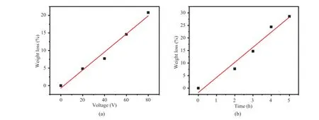
Since Ta is leaching into the electrolyte during electrochemical etching, the weight loss percentage is measured (Fig. 7). The weight loss percentage shows a nearly linear relation with etching voltage and etching time, highlighting the controllable manner of electrochemical methods. Similar with Ra values, the weight loss percentage shows a steeper slope with etching time than etching voltage.
3.2 Capacitance enhancement by electrochemical etching
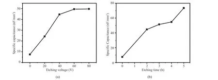
The specific capacitance of the pristine Ta foil and etched Ta foils are summarized in Fig. 8. In line with Ra and weight loss percentage, the specific capacitance steadily increases with etching voltage (Fig. 8(a)) and time (Fig. 8(b)). Fig. 8(a) shows that the increase of etching voltage leads to the increase of weight loss, and accordingly, the specific capacitance goes up, except for the etching voltage of 80 V, where the specific capacitance almost levels up with 60 V. The weight loss is nearly proportional to the applied voltage in the range from 20 V to 80 V, while the increase of specific capacitance slows down at higher voltage, which may indicate the limited effect of applied voltage on the specific capacitance. It means that the high voltage, such as 80 V, can still increase the weight loss, but does not contribute to the enhancement of surface roughness.

Fig. 7 Weight loss percentage of (a) Ta foils etched with various voltages for 2 hours, and (b) Ta foils etched with 40 V voltage for various hours图7 以电压和时间为变量时钽箔蚀刻后质量变化:(a) 钽箔在不同电压下蚀刻 2 h 的失重百分比;(b) 钽箔在 40 V 电压下蚀刻不同时间的失重百分比

Fig. 8 Specific capacitance of (a) Ta foils etched with various voltages for 2 hours, and (b) Ta foils etched with 40 V voltage for various hours图8 以电压和时间为变量时钽箔蚀刻并氧化后电容值的变化:(a) 钽箔在不同电压下蚀刻 2 h 的电容值;(b) 钽箔在 40 V 电压下蚀刻不同时间的电容值
The longer etching time results in more weight loss, and the specific capacitance is raised simultaneously, as displayed in Fig. 8(b). Although the SEM images does not show clear difference between the samples with difference etching time, the specific capacitance varies among these samples. It is speculated that the longer etching time at 40 V contributes to deeper etching, thereby increasing the weight loss. At the same time, deeper etching results in the increase of specific area, thus, the specific capacitance is raised.
3.3 Capacitive performance of Ta electrolytic capacitors fabricated with etched Ta foils

Fig. 9 Capacitive performance of the Ta electrolytic capacitor fabricated with Ta-40V5H anode, (a) capacitance over the frequency range of 100 Hz~110 MHz with the capacitor area 3 mm×3 mm, (b) equivalent series resistance (ESR) over the frequency range of 100 Hz~110 MHz, (c) the leakage current under 10 V DC voltage, and (d) the comparison of capacitance variation between the thin-film tantalum capacitor and commercial tantalum capacitor over the frequency range of 100 Hz~110 MHz图9 采用 Ta-40V5H 钽芯子制作钽电解电容器,在频率为 100 Hz~110 MHz 时测试其电学性能:(a)电容值的变化; (b)等效串联电阻的变化; (c)10 V 直流电压下的泄漏电流;(d)薄膜钽电容器和商业钽电容器电容变化对比
The electrochemically etched Ta foil, Ta-40V5H, was fabricated into Ta electrolytic capacitor after oxidation and the deposition of cathode material (Poly(2,3-dihydrothieno-1,4-dioxin), graphite layer and silver layer). The frequency dependent capacitance and Equivalent Series Resistance (ESR) are summarized in Fig. 9(a) & (b). The Ta electrolytic capacitor based on etched Ta foils shows a high capacitance of >250 nF at the frequency of 1 kHz, and more than 70% of the capacitance is maintained even when the frequency rises to 1 MHz, as shown in Fig. 9(a). As seen from Fig. 9(b), the ESR is about 1 Ω at the low frequency range (<10 kHz), and gradually decreases to 0.5 Ω at MHz level. The leakage current under 10 V is shown in Fig. 9(c), and a relatively stable leakage current of ~10-6A is exhibited which is slightly larger than the commercial capacitor. The effective frequency is more than two orders of magnitude higher than commercial Ta electrolytic capacitors (Fig. 9(d)). The effective frequency of traditional Ta electrolytic capacitors is usually limited to 10 kHz, because the highly porous structure contains large amount of cascaded resistance-capacitance (RC) networks, which causes capacitance drop as frequency rises over 100 kHz[20]. The etched surface can diminish this phenomenon, since the cascaded RC network is restricted on the Ta surface with electrochemical etching method. However, there are disadvantages for embedded tantalum capacitors based on electrochemically etched Ta anode. One is that they are prone to short circuit, so tantalum capacitors are usually used at reduced voltage. As shown in Fig. 9(d), the leakage current of the capacitor is about 2×10⁻⁶A, which is slightly larger than that of the commercial capacitor.
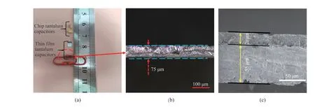
The size of fabricated Ta electrolytic capacitor is compared with the commercial one in Fig. 10(a). A thickness of ~75 μm of our Ta electrolytic capacitor is highlighted in Fig. 10(b), while the commercial Ta capacitor has thickness of ~1.6 mm. A cross-sectional SEM image of the Ta electrolytic capacitor fabricated with Ta-40V5H anode is shown in Fig. 10(c). The thickness of the anode is about 55 μm, while the cathode material accounts for a thickness of around 20 μm. A total thickness of ~75 μm endows this Ta electrolytic capacitor configuration a promising potential for its application as embedded capacitors in IC industry.

Fig. 10 (a) Sizes of chip tantalum electrolytic capacitors and thin film tantalum electrolytic capacitors, (b) optical microscope cross section of tantalum thin film electrolytic capacitor, and (c) SEM cross section of tantalum film electrolytic capacitor图10 钽薄膜电解电容器的实物图:(a)片状钽电解电容器和薄膜钽电解电容器的尺寸;(b)钽薄膜电解电容器的光学显微镜截面图;(c)钽薄膜电解电容器的 SEM 截面图
3.4 Discussion and analysis
Ta and Nb foil etching has been reported[26-28], but the etching results were mediocre according to their SEM images, and the etched Ta or Nb foils were not made into capacitors. In this study, in order to apply the etching method to tantalum capacitors, a thin Ta electrolytic capacitor has been developed based on electrochemically etched Ta foils, and an enhanced capacitance is demonstrated. On the other hand, tantalum thin film capacitors have been studied at home and abroad with the method of tantalum powder sintering[19,20,32]. Electrochemical etching of Ta foils, instead of tantalum powder sintering, has less cost and simpler fabrication process. However, compared with the method of tantalum powder sintering, the capacitance of thin film tantalum capacitors prepared by electrochemical etching is smaller. In addition, the electrical property of tantalum capacitors produced by electrochemical etching needs to be improved, especially the proneness to short circuit.
4 Conclusions
In conclusion, we proposed the use of electro- chemical etching as an efficient method to produce thin Ta anode to facilitate its application as embedded capacitor. Both qualitative and quantitative techniques are used to characterize the influence of electrochemical etching on the surface roughness. The applied voltage and the electrochemical etching duration play important roles in determining the surface roughness, which shows a very close relation with specific capacitance. By optimizing the electrochemical etching parameters, the specific capacitance of etched Ta anode can reach as high as 74 nF/mm2. The Ta electrolytic capacitor device fabricated based on the etched Ta foils shows a stable capacitance of >30 nF/mm2in the frequency range of 100 Hz~1 MHz, and a low leakage current of 2.7×10⁻⁶A under 10 V DC. The electrochemical etching of thin Ta foils holds promising potential to produce Ta electrolytic capacitor for embedded application.
