Response evaluation of a compact and highly efficient neutron diffractometer for compact accelerator neutron sources
2021-01-28ShoImaiKenichiWatanabeAstushiYamazakiSachikoYoshihashiAkiraUritaniSeijiTasakiSetsuoSatoh
Sho Imai,Kenichi Watanabe,Astushi Yamazaki,Sachiko Yoshihashi,Akira Uritani,Seiji Tasaki,Setsuo Satoh
(1.Nagoya University,Furo-cho,Chikusa-ku,Nagoya,464-8603,Japan;2.Kyoto University,Yoshidahonmachi,Sakyo-ku,Kyoto,606-8501,Japan;3.High Energy Accelerator Research Organization,Oh-ho,Tsukuba,305-0801,Japan)
Abstract:We fabricated the spheroid neutron diffractometer with 79 neutron detector rings using the transparent rubber sheet type Eu:LiCaAlF6 scintillators and wavelength-shifting fibers.We confirmed that the fabricated detector shows a clear neutron peak and can discriminate neutron and gamma-ray events in a signal pulse spectrum.We additionally checked that the fabricated diffractometer can detect a neutron diffraction peak of ferrite powder at Kyoto University Accelerator-driven Neutron Source.Consequently,it can be expected that crystal structural analysis will be possible even by small accelerator neutron sources.
Key words:TRUST Eu:LiCAF scintillator;neutron diffractometer;neutron detector;time-of-flight;KUANS;LiTA12
1 Introduction
Neutron diffraction is one of the crystal structural analysis methods of materials.Neutron diffraction technique has some advantages compared with X-ray diffraction.Neutrons have high penetration power for many materials,and can be applied for light element analysis.However,at present,neutron diffraction experiments can conducted only at relatively large facilities with high neutron flux.In order to overcome such a situation,many Compact Accelerator Neutron Source (CANS) facilities have been developed and are under development.Because researchers usually suffer from getting beamtime of the large neutron facilities,it is important to effectively use the CANS facilities to promote development of neutron applications.To conduct neutron diffraction experiments at the CANS facilities with relatively low neutron flux,it is important to apply a highly efficient diffractometer.Therefore,a neutron diffractometer for the CANS facility is desired to have a large solid angle.
Neutron diffractometers covering a large solid angle are generally large and very expensive equipment.In this study,we propose a compact neutron diffractometer with a large solid angle that can be operated with a pulse mode.The pulse mode operation is essential to apply time-of-flight (TOF) analysis at pulsed-neutron source facilities.The proposed compact neutron diffractometer consists of multiple detector rings.A sample is surrounded by a spheroid shape detector formed by multiple detector rings with various diameters.These detector rings can easily be fabricated by using Transparent Rubber Sheet type Eu:LiCaAlF6(TRUST Eu:LiCAF) scintillators,which are originally developed by our research group[1].This type of scintillators is highly flexible and can be easily formed into a ring shape.Additionally,by using a wavelength-shifting fiber (WLSF) readout,scintillation photons can efficiently be collected from a long and thin scintillator.
In this paper,we fabricate the compact,highly efficient and spheroid shape neutron diffractometer and evaluate the response.
2 Details of the fabricated neutron diffractometer
To fabricate a spheroid shape detector,the ring shape neutron detectors are arranged in axial symmetry with respect to an incident neutron beam axis.An ideal scintillator mount configuration is to keep the bottom surface of the scintillator perpendicular to the sample direction in order to keep the detector response uniform for all scattering angles.However,in this way,it is difficult to fabricate complicate support structure for the flexible TRUST Eu:LiCAF scintillator.Therefore,we chose the second option.The ring detectors were arranged to cover a large solid angle but to avoid overlapping each other when seeing each ring detector element from the center of diffractometer that is the sample position.Consequently,the whole diffractometer shape became a rugby ball shape.The cross-sectional size of a long bar shape TRUST Eu:LiCAF scintillator was 4 mm square.The diffractometer consists of 79 scintillation detector rings.For this detector configuration,we performed simulation calculation to evaluate the scattering angle resolution by using a Monte Carlo code PHITS with JENDL 4.0 library[2-3].When the sample size was set to be 5×5×5 mm3,the scattering angle resolution was estimated to be 2° or less at FWHM.Figure 1 shows the schematic drawing of the fabricated neutron diffractometer.
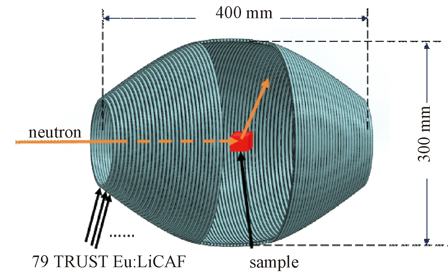
Fig.1 Schematic drawing of the fabricated neutron diffractometer.Each ring represents a scintillator ring made of a Eu:LiCAF scintillator.The sample was placed at the center of the diffractometer
Scintillation light from a TRUST Eu:LiCAF scintilltor was readout by using WLSFs (Kuraray,B-3).The WLSF passed through a long bar shape TRUST Eu:LiCAF scintillator.They were covered with Teflon tape to reflect and collect the scintillation photons.Since the bar type detector is flexible,it can easily be formed into a ring shape.A number of the ring shape neutron detectors were mounted on an aluminum support structure,and the neutron diffractometer shown in Figure 1 was manufactured.This aluminum support has a thickness of 5 mm to assure its structural strength.It was estimated that about 4% of the neutrons are scattered by this aluminum structure.The fabricated neutron diffractometer is shown in Figure 2.
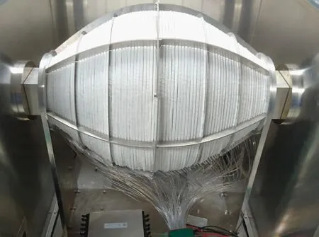
Fig.2 Fabricated neutron detector.These detector elements are covered by the light shielding box.An aluminum square tube penetrates the shielding box. Therefore,samples can be changed without opening the light shielding box
The WLSFs were connected to a multianode preamplifier tube (MAPMT;Hamamatsu,H8500) with 64 pixels.The both ends of each fiber were connected to two pixels,and a signal-emitting detector ring was identified by coincidence counting at specific two pixels.The 79 detector rings were divided into 9 groups each with 9 or 8 detectors.One ends of 9 or 8 fibers in each group were bundled and connected to one PMT pixel.Another ends of fibers were divided into 9 groups not to overlap fibers in the same detector group.This ends of fibers were also bundled and connected to one PMT pixel.Consequently,158 fiber ends were divided into 18 groups.The signal-emitting detector ring can be identified by combination of coincident pixels.As a result,signals from 79 detectors can be individually read out with only 18 pixels.Because the required number of PMT pixels was small,it was not necessary to use adjacent pixels,and the crosstalk effect in MAPMT can be reduced.This configuration additionally has an advantage not to use the outermost pixels,in which a noise level might be severe.To read out signals from the MAPMT,the LiTA12 system was applied[4],which has 64 channel ADCs of 10 bit and 50 MHz.
3 Experimental setup
3.1 Neutron response evaluation
We performed the response evaluation of the fabricated detector using252Cf neutron source surrounded by a polyethylene moderator brick.To evaluate gamma-ray response,the detector was also irradiated with gamma rays from60Co source.To obtain the pulse height of each detector ring,the geometric mean of the pulse heights from two ends of a WLSF was calculated.Because scintillation light intensity exponentially decreases with increasing transmission length in the WLSF,interaction position dependency of the signal pulse height can be cancelled by using the geometric mean of the both pulse heights.The pulse height distribution obtained from the fabricated diffractometer irradiated with neutrons from a252Cf source is shown in Figure 3.
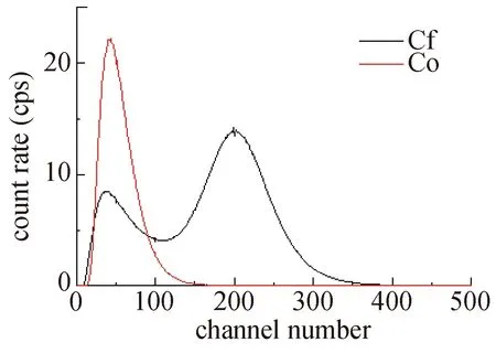
Fig.3 Pulse height spectra obtained from the fabricated diffractometer irradiated with neutron and gamma-rays from 252Cf and 60Co sources,respectively
As shown in Figure 3,clear neutron peaks can be seen.In this figure,the signal gain of each detector rings was calibrated to have a peak at 200 ch.In addition,it is confirmed that gamma-ray events can be distinguished from neutron events in the pulse height spectrum.
3.2 Neutron diffraction experiments
Neutron diffraction experiments for an iron powder sample were conducted at KUANS[5].Figure 4 shows the experimental setup.The detector was installed at a distance of approximately 3.4 m between a moderator surface and the center of the diffractometer.A large sample was used to increase the signal intensity of the diffracted neutrons.The iron sample power was loaded into a cylinder tube with 16 mm diameter and 35 mm height.It should be noted that the sample case is made of 1 mm thick aluminum and can be a scattering source of neutrons.Time-of-flight experiments were performed using the accelerator-based pulsed-neutron source.
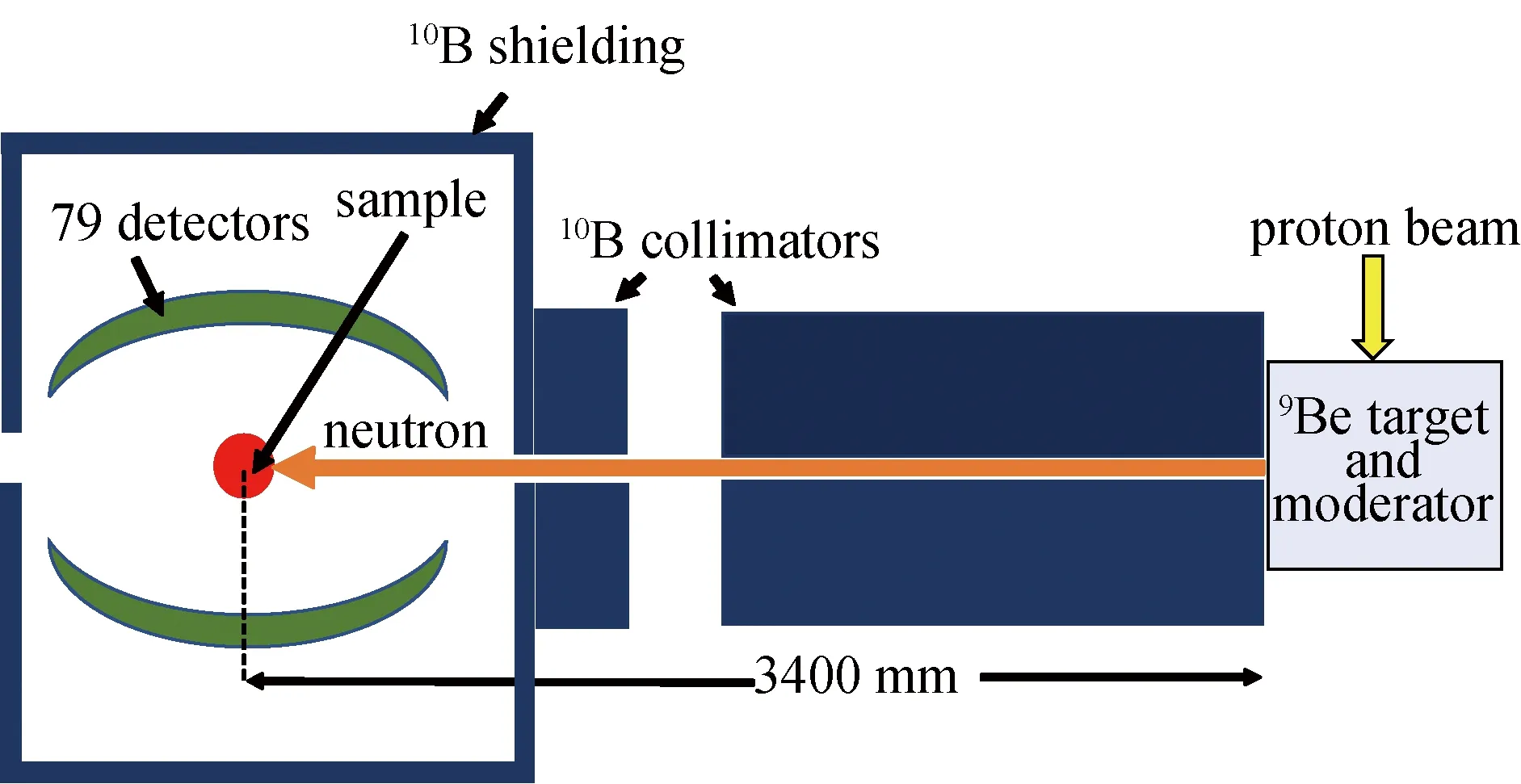
Fig.4 Experimental setup of neutron diffraction experiments.The fabricated neutron diffractometer was covered with B4C sheets in order to shield neutrons injecting from undesired directions
4 Results and discussion
Figure 5 shows the two-dimensional map of the scattered neutron intensity between the TOF and scattering angle.The scattering angle can be determined by identifying the detector ring.The relation between the neutron diffraction angle and TOF for a specific crystal lattice plane is written by
(1)
wheredhkl,lattice spacing;h,Planck’s constant;t,TOF;mn,neutron mass;l,flight distance;andθ,diffraction angle.By modifying this equation,the following equation can be obtained.
(2)
From Equation (2),the TOF increases with increasing the diffraction angle for neutron diffracted from a specific lattice plane.In Figure 5,it can be confirmed that the TOF increases with increasing the diffraction of scattering angle.From the fact that an oblique curve was observed,it was considered that diffracted neutrons could be detected.

Fig.5 Two-dimensional map of the scattered or diffracted neutron intensity between the TOF and scattering angle.The oblique curve represents diffracted neutrons.Because two WLSFs were broken, no signal was acquired from these two detectors
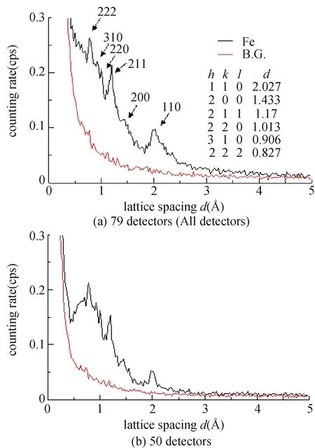
Fig.6 Crystal lattice spacing spectra obtained from an iron powder sample.Spectra (a) were obtained by all the detectors and spectra (b) were obtained by only 50 detectors with higher diffraction angle
The crystal lattice spacingdcan be calculated from the TOF and diffraction angle by using Equation (1).Figure 6 shows the calculated lattice spacing spectra.Diffraction peaks of an iron powder sample was clearly observed in Figure 6.The resolution of the lattice spacing obtained from the diffractometer is described as
(3)
In our diffractometer,the lattice-spacing resolution dominantly depends on the term of tanθespecially for detectors with small diffraction angleθ.This means that detectors with small diffraction angles have worse resolution of the lattice spacing.Therefore,when avoiding signals from these detectors,we can expect to have a good resolution.Figure 6 (b) shows the lattice spacing spectra using only 50 detectors with higher diffraction angles.From this result,the lattice spacing resolution Δd/dof the {110} plane reflection was evaluated to be approximately 6%.
5 Conclusion
We fabricated a compact and highly efficient neutron diffractometer using TRUST Eu:LiCAF scintillators and WLSF readout.Coincidence counting allows simultaneous signal acquisition from 79 detectors with a relatively small number of the PMT pixels.The response to neutrons was evaluated by irradiating the fabricated detector with neutrons from252Cf source.The detector was confirmed to show a clear neutron peak in the pulse height spectrum.In neutron diffraction experiments at KUANS,we demonstrated that the fabricated diffractometer can detect clear diffraction peaks from an iron powder sample.The lattice spacing resolution of the {110} plane reflection was evaluated to be approximately 6%.Further improvement of the resolution can be expected by reducing the sample size and shortening the time width of the neutron pulse.
Acknowledgements:The aluminum support structure of the detector was manufactured by Mr.Shintaro Goto of Technical Support Office,Nagoya University.Many thanks for his effort to realize the complicate structure.
