Filtering Method of Aero-engine Load Spectrum Based on Rain Flow Counting
2021-01-27,,,
,,,
College of Energy and Power Engineering,Nanjing University of Aeronautics and Astronautics,Nanjing 210016,P.R.China
(Received 27 February 2019;revised 1 May 2020;accepted 26 July 2020)
Abstract:A filtering method of aero-engine load spectrum based on the rain flow counting is proposed in this paper.Firstly,the original load spectrum is counted through the rain flow method to get the peak and valley values.Then,some data points in the original load spectrum are added between the peak and valley values.Finally,the filtering spectrum is obtained.The proposed method can reflect the path information of the original load spectrum.In addition,it can also eliminate the noise in the signal and improve the efficiency of signal processing,which is of practical significance for the research of aero-engine.
Key words:load spectrum;filtering;rain flow counting;aero-engine
0 Introduction
The original load spectrum of aero-engines is also known as the measured load spectrum,which is obtained from the flight measurement and flight mission investigation,and can be directly used in the life prediction and life extension.The flight parameters record the work of the aircraft and the information of the flight state.The load spectrum can be used for the daily maintenance,flight training and accident analysis of the aircraft.However,the measured data of aero-engine is huge and its processing is very complicated.Therefore,in the load processing,filtering technologies are considered to be able to eliminate or attenuate noise inference and to extract useful information contained in the signal,which is of practical significance for the compilation of load spectrum and the analysis of load properties[1-2].
At present,the commonly used filtering method in engineering is high pass or low pass filtering.Its main purpose is to remove the noise in the signal.Wu et al.[3]introduced an inverse filtering method in signal analysis.In the processing of road simulation load spectrum,Song et al.[4-5]used Fourier low pass method to carry out the filtering.Liu et al.[6-7]calculated the maximum principle stress of each measuring point in the frame structure by spectrum analysis and low pass filtering.However,the load spectrum of aero-engine is closely related to the use.For example,when the engine is in the state of maneuverable flights,the normal overload coefficient changes with the change of revolution speed.Actually,it is corresponding to several maneuverable flight actions.So its filtering method is different from the general signal filtering method.For aero-engine load spectrum,the small load removal is to filter the load which contributes little to the damage.Conover et al.[8]thought that removing the load whose amplitude was 10%of the maximum load had no impact on the fatigue life.Jiang et al.[9]carried out the filtering from two aspects:(1) Removal of load with small amplitude;(2) removal of load with small peak value.Zhang et al.[10-12]used Kalman method to carry out the filtering for the aero-engine load spectrum.All of these methods used the filtering threshold to eliminate small cycles,while ignoring the load sequence of the original load spectrum,and they contained too many empirical components.Therefore,it is necessary to propose a filtering method which is suitable for the actual use of aeroengine.
Among flight parameters of aero-engines,the normal overload coefficient is the one that can mostly reflect the change of maneuverable actions.Normal overload coefficient is a spectrum compiled by the time history of the engine’s center of gravity normal overload.This spectrum is used as the basic input for compiling the aero-engine intermediary case and load spectrum or stress spectrum of other load-bearing components.It is one of the important parameters in the structural reliability design of aircrafts and aero-engines,and also one of the contents that need to be evaluated in the test flight of aircraft and aero-engines.Consequently,taking the normal overload coefficient as an example,a filtering method of aero-engine load spectrum is put forward based on the rain flow counting.The proposed method preserves the path information of the original load spectrum and effectively removes the noise in the signal.Furthermore,it greatly simplifies the data processing,which is of great engineering significance.
1 Rain Flow Counting Method
In the prediction for fatigue life of aero-engines,the first and critical step is to use the cyclic counting method for statistical analysis of the load spectrum.After that,such load information as amplitude and mean value of the load spectrum can be obtained.In the statistical analysis of load spectrum,the most widely used method is rain flow counting method,which is also called tower-top method.The method considers that the existence of plasticity is a necessary condition for fatigue damage,and the plastic characteristics are shown as stress strain hysteresis loops.Therefore,the rain flow counting method can reflect the whole process of random load[13].The original load spectrum(Fig.1(a))is used to explain the following counting rules.
(1)Rearrange the stress-time history with the highest peak value or the lowest valley value as the starting point,as shown in Fig.1(b).
(2)The rain flows from the inside of each peak or valley in turn,falling down at the next peak or valley.The rain flow stops in the following two conditions:① The rain flow starts at a peak and stops when it encounters a peak equal to or higher than the initial peak;② the rain flow starts at a valley and stops when it encounters a valley equal to or lower than the initial valley value,as shown in Fig.1(c).
(3)The rain flow starts at the peak or valley stops when encountering the other rain flow falls from top to bottom.Then,a cycle can be recorded according to its starting and ending points,as shown in Fig.1(d).
(4)Extract all the total loops,and record their peak values,valley values,amplitudes and mean values.
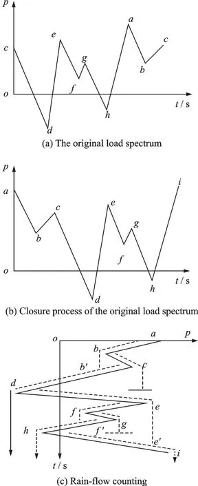

Fig.1 Illustration of rain flow counting method
2 Load Spectrum Filtering Based on Rain Flow Counting Method
2.1 Extraction of peaks and valleys
The original load spectrum of normal overload coefficient of an aero-engine is shown in Fig.2.Through the rain flow counting method,the amplitude and mean value of each cycle are obtained.The rain flow filtering threshold determined in this paper is

whereΔ%is the rain flow filtering threshold,GmaxandGminthe maximum and the minimum amplitudes in the load history,respectively[14].

Fig.2 The original load spectrum of normal overload coefficient
At the same time,the peak and valley values are also obtained.The partial enlarged diagram of the peak and valley values of segment 1 in the original load spectrum is shown in Fig.3.
On this basis,starting from the first data point,by comparing the difference between the adjacent peaks,if the difference is greater than the threshold,the value is deleted.
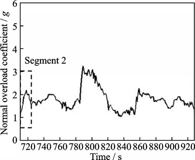
Fig.3 The partial enlarged diagram of segment 1 in Fig.2
The partial enlarged diagram of load segment 2 in Fig.3 is shown in Fig.4.From the first data pointM,the difference value between the latter data pointNand pointMis calculated as

whereδis the difference value,GMandGNthe normal overload coefficient values of pointMandN,respectively.

Fig.4 The partial enlarged diagram of segment 2 in Fig.3
Ifδ≥Δ%,pointNis retained.The comparison of the threshold and the difference value between data pointNand the latter data pointPis carried out to decide the retaining or the deletion of pointP.
Ifδ<Δ%,pointNis deleted.The comparison of the threshold and the difference value between data pointMand the latter data pointPis carried out to decide the retaining or the deletion of pointP.
After the comparison of each data point by this method,the obtained peak and valley values of load segment 1 based on the rain flow filtering threshold are shown in Fig.5.And the peak and valley values of each data point is shown in Table.1.

Fig.5 Peak and valley value diagram of segment 1 in Fig.2 based on rain flow filtering threshold

Table 1 Peak and valley values of segment 1
2.2 Addition of data points of the original load spectrum
On the basis of peaks and valleys obtained above,some data points of the original load spectrum are added between peaks and valleys.Taking the segmentEFandHIin Fig.5 as an example,the segmentEFis defined as the rising edge,while the segmentHIis defined as the falling edge.The original data point located betweenEFand those located betweenHIare extracted to beadded between them.The principle of adding points is that data points added in the rising edge are only allowed to rise,while those added in the falling edge are only allowed to drop.The specific judging method is as follows.
For the rising edgeEF,if the value of the latter data point is larger than that of the previous one,the data point will be added.While if the value of the latter data point is smaller than that of the previous one,the data point will be ignored.As shown in Fig.6,the data points marked as“o”are added,while those marked as“*”are ignored.The filtered load spectrum of rising edge after adding the original data points is shown in Fig.7.
For the falling edgeHI,if the value of the latter data point is smaller than that of the previous one,the data point will be added.While if the value of the latter data point is larger than that of the previous one,the data point will be ignored.As shown in Fig.8,the data points marked as“o”are added,while those marked as“*”are ignored.The filtered load spectrum after adding the original data points is shown in Fig.9.

Fig.6 The original data points between rising edge EF

Fig.7 The filtered load spectrum of segment EF

Fig.9 The filtered load spectrum of segment HI
Using the above method,the final filtering is completed by judging all data points in turn.The filtered load spectrum of normal overload coefficient is shown in Fig.10.Compared with the original load spectrum in Fig.2,the filtered load spectrum removes the noise in the signal and preserves useful information,which reduces the amount of data processing.

Fig.10 The filtered normal overload coefficient
3 Result Analysis
3.1 Filtering results using high-pass method
In the field of aero-engine load spectrum filtering,the traditionally used method is high-pass filtering method.Since the shifted signal has a long period,its corresponding frequency is very low.Therefore,we can choose a very low threshold to carry out high-pass filtering.Taking the original load spectrum in Fig.2 as an example,the high-pass filtering is carried out.As shown in Fig.11,the black line is the original load spectrum,and the red line is the random disturbance spectrum.The high-pass filtering spectrum is shown in Fig.12.

Fig.11 Random disturbance spectrum

Fig.12 High-pass filtering spectrum
As can be seen from Figs.11 and 12,the highpass filtering spectrum loses a large number of valid data and the maneuverable mission segment has been removed,which is obviously inconsistent with the actual condition.The low cycle fatigue damage caused by the original load spectrum and the filtered load spectrum is consistent.Therefore,it is necessary to propose a new filtering method,which is more suitable for the aero-engine load spectrum.
3.2 Filtering results using small load removal
In order to separate maneuverable mission segments from the original load spectrum effectively,another filtering method is small load removal.Its basic idea is to select a critical value greater than 1,and the load less than the critical value in the original load spectrum is all set as 1.The removal method can separate the maneuverable mission segments effectively.However,the random disturbance still exists in the filtering spectrum as shown in Fig.13.The workload of subsequent load treatment is still very tedious.Therefore,the small load removal method cannot meet the actual needs of aero-engine load spectrum.

Fig.13 The filtered spectrum using small load removal
3.3 Filtering results based on rain flow counting
Compared with the former two methods,the filtering method based on rain flow counting proposed in this paper can not only remove the random disturbance,but also can preserve the valid maneuverable mission segments,as shown in Fig.14.The black line is the original load spectrum,and the red line is the filtering spectrum based on rain flow counting.It offsets the shortcomings of high-pass filtering method and small load removal.Since the filtering method is based on rain flow counting,the low cycle fatigue damage caused by the filtered load spectrum and original load spectrum is consistent.Therefore,the filtering method in this paper is more suitable for aero-engine load spectrum,which is of practical engineering significance.The process of the filtering method is shown in Fig.15.

Fig.14 The filtered normal overload coefficient

Fig.15 Process of the filtering method based on rain flow counting
4 Conclusions
In this paper,a filtering method of aero-engine load spectrum based on rain flow counting is proposed.It includes two steps:
(1)Extracting peaks and valleys of the original load spectrum based on the rain flow counting method.
(2)Adding the data points of the original load spectrum between the peaks and valleys.
The method preserves the path information of the original load spectrum and can effectively remove the noise in the signal,which improves the efficiency of signal processing.It provides a new method for the research of flight parameter preprocessing and the elimination of wild point in the compilation of aero-engine load spectrum.This method combines the rain fall counting method with the filtering method,which shows innovative,and is more applicable to the processing of aero engine load spectrum.
杂志排行

Transactions of Nanjing University of Aeronautics and Astronautics的其它文章
- Research on Flexible Flow-Shop Scheduling Problem with Lot Streaming in IOT-Based Manufacturing Environment
- Mathematical Model and Simulation of Cutting Layer Geometry in Orthogonal Turn-Milling with Zero Eccentricity
- Two Different Role Division Control Strategies for Torque and Axial Force of Conical Bearingless Switched Reluctance Motor
- Accuracy Compensation Technology of Closed-Loop Feedback of Industrial Robot Joints
- Mold Wear During Die Forging Based on Variance Analysis and Prediction of Die Life
- Nonlinear Dynamic Analysis of Planetary Gear Train System with Meshing Beyond Pitch Point