Robust Lane Detection and Tracking Based on Machine Vision
2021-01-19FANGuotianLIBoHANQinJIAORihuaQUGang
FAN Guotian,LI Bo,HAN Qin,JIAO Rihua,QU Gang
(1.ZTE Corporation,Shenzhen 518057,China;2.Xidian University,Xi'an 710071,China)
Abstract: Lane detection based on machine vision,a key application in intelligent transportation,is generally characterized by gradient information of lane edge and plays an important role in advanced driver assistance systems (ADAS).However,gradient information varies with illumination changes.In the complex scenes of urban roads,highlight and shadow have effects on the detection,and non-lane objects also lead to false positives.In order to improve the accuracy of detection and meet the robustness requirement,this paper proposes a method of using top-hat transformation to enhance the contrast and filter out the interference of non-lane objects.And then the threshold segmentation algorithm based on local statistical information and Hough transform algorithm with polar angle and distance constraint are used for lane fitting.Finally,Kalman filter is used to correct lane lines which are wrong detected or missed.The experimental results show that computation times meet the real-time requirements,and the overall detection rate of the proposed method is 95.63%.
Keywords:ADAS;Hough transform;Kalman filter;polar angle and distance;top-hat
1 Introduction
With the expansion of car ownership,the number of traffic accidents has also increased.Many of the accidents are caused by driver's negligence or visual disturbance.Advanced driver assistance systems (ADAS) are considered to be important technologies for reducing accidents,such as lane departure warning (LDW),lane keeping.Lane detection based on machine vision is the basis of these and other similar applications and is a key technology in ADAS to assure active driving safety[1].Meanwhile,lane detection provides support for road identification,obstacle detection and other applications to realize driving safety[2].Furthermore,on the basis of accurate detection,plenty of applications of intelligent transportation can be improved,such as road navigation,lane-positioning,and lane-level mapping[3-4].Considerable work has been done and various methods proposed to detect lane lines.The methods usually consist of two main steps:lane feature extraction and lane fitting with a parametric curve.The extraction of the candidate point is a key step in lane detection.If the feature points of the lane cannot be extracted accurately,it is difficult to make up for it in the subsequent processing.In these lane detection methods,color,texture or edge information is considered as a feature of the lane.
Because the lanes and road surface have contrasting colors,various color-based[5-6]methods have been proposed.HE et al.[5]proposed a road-area detection algorithm based on color images,which is composed of two parts.First,the left and right road boundaries are estimated by using edge information.Then,road areas are subsequently detected based on the full color image by computing the mean and variance of the Gaussian distribution.Color information can be used to constrain road surface areas.However,this method has a drawback that the shadow and water on road surface have an effect on road area detection.SUN et al.[6]transferred an image into the hue saturation intensity(HSI) color space and used a threshold computed by fuzzy cmeans to do intensity difference segmentation.Finally,the image was filtered by means of connected component labeling(CCL)of binary image.CHENG et al.[7]presented a lane-detection method aiming at handling moving vehicles in the traffic scenes,and removing non-lane objects,such as road traffic signs.Lane lines are extracted by color information without being affected by illumination changes.If vehicles have the same colors as lane lines,they can be distinguished by shape,size,etc.However,this method has disadvantages of using a pre-defined threshold and limited scenarios.Thus,it is difficult to distinguish lanes and roads by using color differences in outdoor road environment when the illumination changes with time,weather,etc.
Other methods to overcome this disadvantage of using the color cues for lane detection is to utilize texture features,vanishing points[8]or region of interest (ROI) constraints[9-10].YOO et al.[8]proposed a lane detection method based on vanishing point estimation using the relevance of line segments,combined with the vanishing point.The false detections decrease by filtering out lines that do not pass through it.However,this method has high computational complexity and long processing time.BORKAR et al.[9]exploited the parallel nature of lane boundaries on the road to find near parallel lines separated by a constraint specified distance and then false signaling caused by artifacts in the image can be greatly reduced.LIU et al.[10]combined ROI with perspective transform.It firstly detects the lane lines on the road,then determines the trapezoid ROI where road marking would show up with the guide of detected lane lines,and finally the ROI is transformed to square by inverse perspective transform for accurate road marking detection and recognition.DENG et al.[11]adopted inverse perspective mapping (IPM)transform model for the ROI.Then,the template is designed according to the specific pixel value,width,edge orientation of lane marking,and gray distribution of two sides of the lane.It is effective to filter out the interference of vehicle edges ahead or shadows of objects such as telegraph poles,traffic signs,and trees.However,the effectiveness of IPM-based technique would be reduced if there are obstacles in the road.
Apart from the above methods,gradient-enhancing[12-15]detection methods are widely used to detect lanes,since it can increase the contrast between the lane and the road surface and reduce the influence of illumination.A vision-based autonomous detection method of lane was proposed in Ref.[12].It sets an ROI in the image,the pixels in which are investigated along multiple horizontal scanning lines,and a lane line in the image is determined by connecting the two center points or fitting a set of multiple center points.However,it can only detect left and right line of the current lane.When there are more lane lines or other objects with higher brightness,the error rate will increase dramatically.LI et al.[13]employed histogram equalization to adjust the contrast and fit the lane by using Hough transform or B-spline curves.YOO et al.[14]proposed a gradient-enhancing conversion method for illumination-robust lane detection.They proposed gradient enhancing conversion method to convert images which have large gradients at lane boundaries.This method combines Hough transform and curve model to detect lane lines.HALOI et al.[15]used a modified IPM to obtain ROI,where 2D steerable filters are used to capture gradient changes due to color variation of road and lanes.
In the outdoor road environment,illumination changes with time,weather and light,etc.Lanes and roads have similar gray values,and the gradients of them are not obvious.Thus,lane and road information can be easily converted into similar values,which is not conducive to feature extraction.The method based on the gradient is limited to specific scenarios.During the process of lane detection,the main task is to maximally highlight and enhance the lane marking,meanwhile,suppress or filter out non-lane interference.This paper proposes an efficient method for illumination-robust lane detection and tracking.Our method uses the top-hat transformation to enhance the contrast and filter out the interference of some non-lane objects,which maximizes gradients of lanes and roads.Then a progressive threshold segmentation algorithm based on local statistical information and constrained Hough transform with polar angle and distance is used for lane detection.And finally,Kalman filter is used to correct lane lines that are wrong detected or missed.Specifically,contributions of this paper are presented as follows.
(1) We put forward a top-hat transformation to enhance the contrast of lane lines and background images and filter out the interference of non-lane objects.
(2) The lanes are detected efficiently by constrained Hough transform with polar angle and distance.Then,it is corrected by using Kalman filter.
(3) The simulation implemented validates the proposed method.It can effectively detect lane lines in scenarios such as shadows,glare,rain and night,and meet the real-time and robust requirements to different scenarios.
The remainder of the paper is organized as follows.Section 2 gives a detailed description of the proposed approach.Section 3 describes test results under different illumination scenarios.Finally,Section 4 concludes the paper.
2 Lane Detection and Tracking
Fig.1 shows the flow chart of the lane detection method.This method does not need to calibrate the camera,but directly uses the pixel coordinates for lane detection.First,ROI,grayscale image transformation and image filtering are used for pre-processing.Then,the top-hat transformation,thresholding and edge detection are used to obtain edge image,followed by a progressive Hough transform used for lane detection.Finally,Kalman filter is used to correct lane lines that are wrong detected or missed.
2.1 Pre-Processing
The video frames we collect contain not only the part of the lane,but also various background noises,such as the sky,vehicles,trees and houses,which will have certain influences on the detection.In order to accurately capture the lane features and avoid noise interference,we firstly obtain the part of the image containing the lane area,and filter out the noise generated in the process of image capturing.The pre-processing stage includes the selection of the ROI,grayscale image transformation,and image filtering.Fig.2 shows the results of the pre-processing.
(1)Selection of ROI.
Since the upper half of an image is the sky,the lane line only exists in the lower half of the image.There is no target object in the upper part of the image,which will cause interference with the detection.In order to reduce the amount of calculation and avoid the interference,the sky area is removed,and only the part containing the lane is left.The rectangular ROI is configured in the initialization stage.It includes the road region only when the region above the vanishing point(VP) is removed.If the size of an image isM×N,we take the lower half of the image as the rectangular ROI,that is,the size of ROI isM2 ×N.
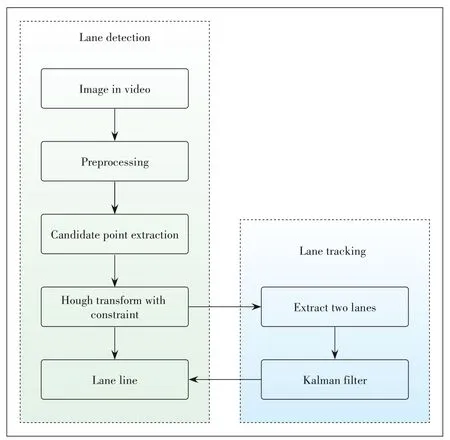
▲Figure 1.Flow chart of lane detection and tracking method.
(2)Red Green Blue(RGB)to gray.
The road image obtained from the driving recorder is RGB format,but the detection of lane lines is mainly based on gray and edge information.Therefore,RGB images should be converted to grayscale images to reduce the image storage capacity and improve the operation speed.
(3)Filtering operation.
Inevitably,in the process of image acquisition,noises will intrude.The effect of isolating noise on the image is great.Median filter can achieve much better noise suppression with minimum edge blurring than other methods.
2.2 Candidate Point Extraction
After image pre-processing,candidate lane line points should be extracted before lane fitting.The extraction of lane features is a key step in lane detection.If lane features fail to be accurately extracted in this step,it is difficult to make up for the subsequent lane detection steps.The steps of candidate point extraction consist of top-hat transformation,binarization and edge detection.
2.2.1 Top-Hat Transformation
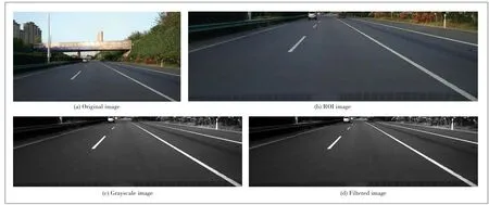
▲Figure 2.Pre-processing results.
We use a top-hat transformation[16]as one step of candidate point extraction to enhance the contrast of the lane and the background,and filter out the interference of non-lane objects.In the field of mathematical morphology,the top-hat transformation is an operation of gray scale morphology,which can extract brighter small elements and details from given images.The operation is achieved by subtracting the open image from the original image.The top-hat operation has the following features:1)The open operation is used to remove small details with highlights,while retaining all the gray levels and ensuring that the features of a larger bright area are not disturbed.Therefore,the top-hat transformation highlights areas that are brighter than the region around the original image contour by subtracting the open operation from the original image,and this operation is related to the size of the selected kernel;(2) Top-hat operations are often used to separate plaques that are brighter from adjacent ones.When an image has a large background,and the tiny items are more regular,the top-hat operation can be used for background extraction; (3) The top hat operation is commonly used to detect peak structures in the image,while it is used for feature extraction in this paper.The top-hat operation is computed as:

wherefdenotes the filtered image,Fdenotes the result image,andbdenotes the structuring element,which is the key of tophat transformation.The size ofbshould be greater than the width of the lane line.Herei'andj'belong tob.The top-hat transformation can obtain the target image that has been eliminated by the opening operation,by subtracting the opening image from the filtered image.The opening image is formulated in Eqs.(1)and(2).
The gray histogram is a function of gray level distribution,and it is a statistic of gray level distribution in the image.An image consists of pixels of different gray values,and the distribution of gray is an important feature of an image.In this paper,we extract the grayscale value of a row in the image,and verify the algorithm by observing the grayscale changes of different images.The grayscale distribution of line 90 is shown in Fig.3,in which the abscissa indicates the number of columns of the image and the ordinate indicates the gray value corresponding to the ninth row of the image.The blue line represents the grayscale distribution curve of the target image,the green line denotes the grayscale distribution curve of the opening image,and the orange line represents the grayscale distribution curve of the gray image.
It can be seen from the gray scale distribution that the open operation filters out the highlighted area corresponding to the lane lines and preserves the pixel value of the background region of the road surface.By subtracting the open operation image from the filtered image,the highlighted lanes portion filtered by the open operation is obtained.The resulting image of the top-hat operation is obtained,which effectively enhances the gradient of the boundary between the road surface and the lane lines.Therefore,this algorithm enhances the contrast of lanes and background in the images,according to the structuring element.Figs.4a and 4b show that the top-hat transformation enhances the contrast of lane marking,and meanwhile suppresses or filters out non-lane interferences effectively.
2.2.2 Thresholding
(1)Binary image:The input video images are at first converted into grayscale images frame by frame.The gray image is transformed into 0-1 binary image,where 0 corresponds to the pixels value not or maybe not on the lane lines,and 1 corresponds to the pixels value on or maybe on the lane lines within the images.The thresholding divides the image into 0-1 binary images,preserves the lane lines and filters out other unnecessary details,i.e.,the target and the background.
During this process,the selection of thresholds is particularly important.Only by selecting the appropriate thresholds for image segmentation,the effect of distinguishing lane lines and the noise can be achieved.The distribution of the gray scale of the road image is not bimodal,especially in the shadow and uneven lighting conditions.Thus,there are poor binarization segmentation effects by using basic global thresholds'methods,such as fixed threshold segmentation algorithm,and iterative threshold segmentation algorithm.Thresholding based on local threshold has an advantage over that one.

▲Figure 3.Gray scale histogram.
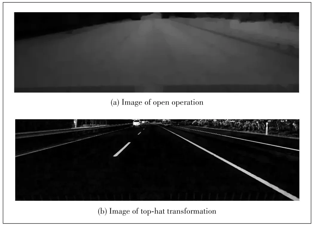
▲Figure 4.Resulting images.
Usually,the binary image still contains a large number of non-lane objects,such as railings and trees.Particularly,when there are shadows or uneven light in the image,white areas appearing in the binary image will result in a sharp deterioration in segmentation performance.A solution is to use variable thresholds,and the threshold for each point is calculated from the characteristics of one or more specified pixels in the neighborhood of that point.In this paper,the top-hat algorithm enhances the image and makes the contrast between the lane line and the road surface more obvious.In the stage of thresholding,the progressive thresholding method based on the mean is still used,but the standard deviation is also introduced.As is known,the mean represents the average gray scale in the neighborhood and the standard deviation represents the local contrast.Thus,a detailed distinction will be possible in binary image by using the standard deviation.The threshold is computed as:

whereF(i,j)is the gray scale of filtered image at(i,j),mrrepresents the mean of the neighborhood,σrrepresents the standard deviation of the neighborhood of 3× 3,andaandbare their corresponding weight.Here,atakes 2 andbtakes 1.5.Fig.5a shows the results of the image thresholding process we use.
(2) Edge detection:After obtaining the lane area by binarization,the edge features of the lane are extracted as the basis of the lane fitting.Vertical gradient edge detection is used to detect image edge by vertical gradient differential,and the mask of[ -1,0,1]is used to smooth image.The imageE(i,j)after the vertical gradient edge detection is defined as:
And so I became skilled at communication. I questioned my teachers until I understood every facet19 of their teaching. It made no difference if the teacher was masterful of inept20; each had a gift for me. Week after week, I learned whatever was set before me in class and taught my father whatever I could.

The image with edge detection is shown in Fig.5b.It is an effective way to convert the binary image into the edge image with one side.
2.3 Lane Fitting
The Hough transform[17]is a method that locates shapes in images,such as line segments,curves,and other patterns.The basic principle is that the form to be sought can be expressed by a known function depending on a set of parameters.A particular instance of the form to be sought is completely specified by a set of parameters representing the form.The Hough transform is so far effectively used for finding lines in images,it is a very common method of extracting curves from images and is widely used to detect lane lines.After obtaining the lane feature points,Hough transform can be used to detect the lane lines.
The Hough transform maps the points on the image space to the parameter space,and detects the lines by simple accumulation in the parameter space and finding the peak value of the accumulator.One point in the image space shown in the parameter space will be a line.In practice,y=k⋅x+bis unable to representx=cin the form of a straight line.So,in the practical application,the parameter equation is used.We can think that the coordinates of one point(i,j) has been known,and the following parameter equation formula is under the principle of Hough transform.

whereρis the distance between the origin of coordinates and lines in image space.θis the angle between lines andxaxis,and-90∘≤θ≤90∘.
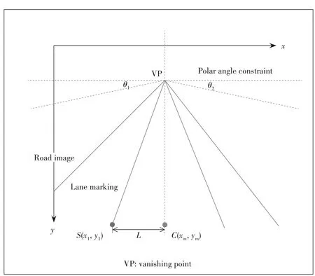
The lane lines are usually parallel in the actual road.However,they will converge at a vanishing point when imaged by the camera.In the course of normal driving,the lane lines are generally on both sides of the vehicle,which are distributed on the left and right sides of the image.Fig.6 shows thatθ1,θ2are the ranges of angles in which lane lines do not need to detect.SandCare the intersection of the lane line and the bottom of the image.The constraint distanceLcan be obtained bySandC.Based on the fact above,we constrain the polar angle and distance,meanwhile,the suppression of the peak is also needed.Lane sets are set toLandR,and countered toNLandNR.Andnpeaks fromH(ρ,θ) are selected.The lane fitting method using Hough transform algorithm with the polar angle and distance constraint is shown in Algorithm 1.

▲Figure 5.Overall detection results.
Algorithm 1.Hough Transformation with Polar Angle and Distance Constraint

▲Figure 6.Polar angle and distance constraint diagram.
wheredm=N2 -xm,1 ≤m≤n,andxmis the horizontal coordinate of the line corresponding toH(ρm,θm) intersects the bottom boundary of the image.The results of the fitting lane are shown in Fig.7,where the red line represents the left lanes,and the green line denotes the right lanes.Under different illumination and road disturbance conditions,lane lines on the left and right sides of the vehicle can be effectively extracted.This algorithm not only avoids the detection of horizontal line as lane line,but also makes the detected lane evenly distributed on both sides of the vehicle,and consequently improves the detection accuracy.
2.4 Lane Tracking
The Kalman filter is frequently employed for object tracking.It is usually assumed that the object moves with constant or linearly varying speed among successive frames[17].In the lane detection process,there are often cases of error or missed detection when lane lines are obscured and unclear.In order to avoid this situation as much as possible and improve the accuracy and robustness of detection,we use the Kalman filter to track the lane line.Since the actual application often uses the lane lines on both sides of the vehicle,this paper only tracks the two lane lines on both sides of the vehicle during the detection and tracking process.
Lane line parameters[ρ,θ,Δρ,Δθ] are the status vector of the traced line,and Δρand Δθare the variations ofρandθ.The state transition matrix and measurement matrix are shown in Eq.(8).


▲Figure 7.Fitting lanes.
When the consecutivekframes are correctly detected,the lane line parameter (ρ,θ) is taken as the initial state of the Kalman filter,and the Kalman filter is started.The fitted lines existing in the repository in step (k-1) are matched as follows by using the difference ofρandθ:

If the detection result of the current frame matches the previous frame,the detected value is used as the current lane line result and the detection counter is incremented by one;otherwise,the filter is called to perform prediction tracking,and the predicted value is used as the parameter of the current lane line.When the detection counter is larger than the threshold,only Kalman is called for lane line detection and tracking.The detection state is returned afterTframes.Here,T1andT2denote as predetermined thresholds for the matching parameter.
3 Experimental Results
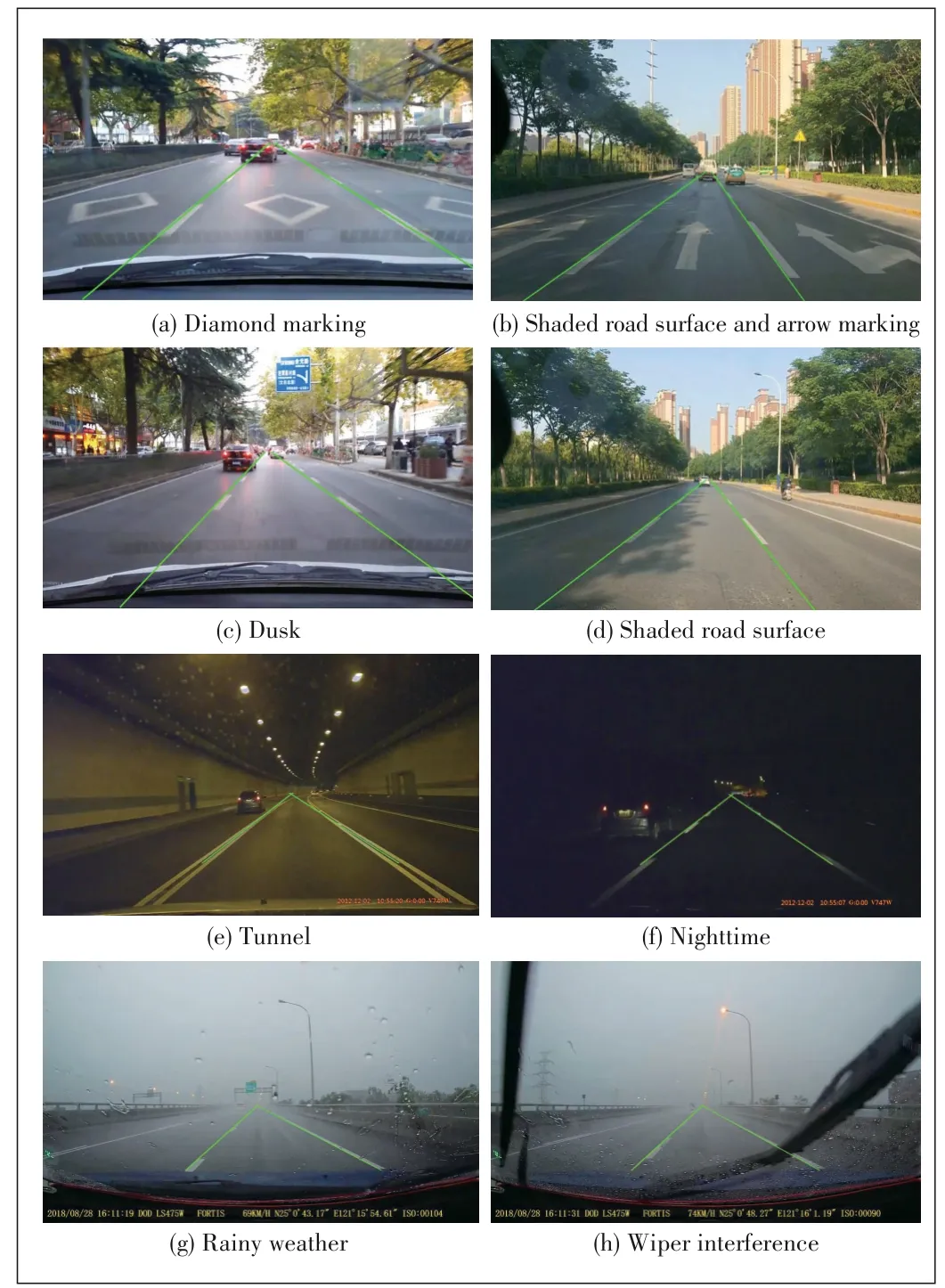
To verify the performance of the algorithm,we make a simulation in Matrix Laboratory (MATLAB).The algorithm is performed on a PC with Intel Core i5-7500 3.4 GHz CPU with 4 GB of RAM.Data sequence 1 and data sequence 2 were collected through a cellphone camera mounted below the rearview mirror of a shared car in Xi'an.Data sequence 1 contains highways.Data sequence 2 contains many multilane roads and mostly urban roads.The dataset corresponds to diamond marking,shaded road surface,arrow marking and Dusk.Data sequence 3 of nighttime and Data sequence 4 of rainy weather were obtained from YouTube.The dataset includes tunnel,rain covered road and wiper interference.To objectively verify the performance of the method,the KITTI dataset[18]was used.Figs.8 and 9 display the detection results,which are represented by green lines.According to HALOI et al.[15],the precision of a lane detection is given by Eq.(10).

where FP denotes false positive and TP denotes true positive.Table 1 shows that the accuracy of detection is improved.Under the highway conditions,the accuracy of detection is 99.80%.Under low lighting conditions,such as nighttime,in a tunnel,the accuracy of detection reaches 98.28%.The accuracy of detection is 97.84% at dusk.Under low light conditions such as at night,the gray scale distribution of the road surface is relatively uniform,and the interference is relatively small,so the detection rate is high.When the road surface has a lot of interference and the lane line is blocked for a long time,the detection rate is relatively low.Under heavy rain conditions,the detection rate is 94.28%,which is the lowest among all conditions,because the lanes are almost invisible and can easily lead to false detections,as shown in Fig.10.
▲Figure 8.Lane detection results under various driving conditions.

▲Figure 9.Results of the KITTI dataset.
Table 2 presents the accuracy of lane detection using the KITTI dataset,and the comparison with the method adopted by HALOI et al.[15].The detection rate of the proposed method is higher than that adopted by HALOI et al.[15].In the scene where the lane lines are obvious and the road surface interferences are less,the lane detection rate reaches above 97%.The overall detection rate is 95.63% and it is greater than 94% in very complex environments.The average running time of each frame is 0.048 s in MATLAB,which meets the realtime requirements and can adapt to different scenarios.
4 Conclusions
This paper proposes a lane detection and tracking method.The pre-processing stage reduces the amount of computation of detection module.After pre-processing,the top-hat transform is used to enhance the contrast and filter out the interference of some non-lane objects.Binarization and edge detection are used to extract feature points.Then,Hough transform algorithm with polar angle and distance constraint is used for lane fitting.Finally,Kalman filter is used to correct lane lines that are wrong detected or missed.The actual road test results show that this method is robust despite of the shadow,uneven lighting and road damage.Experimental results show that the algorithm meets the real-time requirement and can adapt todifferent scenarios,where the average detection rate reaches above 95.63%.In the future,adaptive ROI selection needs to be further studied.

▼Table 1.Lane Detection Results

▲Figure 10.Result under heavy rain conditions.

▼Table 2.Performance for KITTI Dataset
杂志排行
ZTE Communications的其它文章
- Balanced Discriminative Transfer Feature Learning for Visual Domain Adaptation
- M⁃IRSA:Multi⁃Packets Transmitted Irregular Repetition Slotted Aloha
- Feasibility Study of Decision Making for Terminal Switching Time of LEO Satellite Constellation Based on the SGP4 Model
- Advanced Space Laser Communication Technology on CubeSats
- Adaptability Analysis of IP Routing Protocol in Broadband LEO Constellation Systems
- Satellite E2E Network Slicing Based on 5G Technology
