Challenges for beyond 5G:ultra-densification of radio access network
2020-12-10
Research Organization of Electrical Communication,Tohoku University,Sendai 980-8577,Japan
Abstract:Ultra-densification of radio access network (RAN) is a key to efficiently support the exponentially growing mobile data traffic in 5G era.Furthermore,extremely high frequency band like mmWave band was utilized to solve the bandwidth shortage problem.However,untra-dense reusing the same radio resource produced severe interference.And the mmWave link was very harsh due to frequent blockage by obstacles.Therefore a new RAN architecture needed to be introduced to realize ultra-reliable communications in such a severe radio propagation environment.An architecture of distributed MIMO based RAN was presented.Then,enhanced interference coordination (eIC) was described.Finally,the effectiveness of distributed MIMO based RAN with eIC by computer simulation was showed.
Key words:5G advanced systems,distributed MIMO,radio access network,interference coordination,cooperative signal transmission
I Introduction
Taking about 40 years,the mobile communication systems have evolved from the 1stgeneration (1G)systems to the 5thgeneration (5G) systems,as illustrated in Fig.1.5G services started in 2019 and 2020 in many countries.5G systems are designed to support three typical communication services:enhanced mobile broadband communication (eMBB),ultra-reliable and low latency communication (URLLC),and massive machine type communication (mMTC)[1].Fig.2 illustrates the key quality of service (QoS) requirements of 5G systems.Recently,the 6G researches have been intensified worldwide[2-4].So far,we have seen new generation systems almost every 10 years.The 6G systems would appear in around 2030 or even without waiting for 2030.6G systems are foreseen to extend their coverage from terrestrial to air,space,and even underwater areas,i.e.,3-dimensional coverage.They will be designed to provide more intelligently and securely various enhanced combinations of 5G services,e.g.enhanced eMBB+URLLC,enhanced eMBB+mMTC,enhanced URLLC+mMTC,etc.Among many communication services,augmented reality (AR),virtual reality (VR) and mixed reality(MR) will be available in 5G era.Holographic communications may become one of enhanced eMBB+URLLC services.These new ultra-high rate communication services require a huge bandwidth.Although mmWave,an extremely high frequency band,is utilized in 5G systems as a solution to the bandwidth shortage problem,a new frequency band like THz needs to be pioneered.

Fig.1 Mobile communication systems evolution from 1G to 5G

Fig.2 5G services and their key QoS requirements
It is worth noting that the bandwidth shortage problem will happen even in 5G era.The mobile data traffic will not stop increasing.It is expected to increase at a compound annual growth rate (CAGR) of approximately 46%[5].Hence,the traffic volume will reach about 7 times in 5 years after the inauguration of the 5G services.We cannot wait for the arrival of 6G systems and need to continuously enhance the capability of 5G systems.The available but limited radio bandwidth needs to be reused as much as possible even though mmWave band has become available.Ultra-dense radio access network (RAN) is a key to efficiently handle exponentially growing mobile data traffic.However,severe interference will occur when densely reuses the same radio resource.Furthermore,the mmWave link is very harsh due to frequent blockage by obstacles.To support ultra-reliable communications in such a harsh radio propagation environment,the RAN needs to be restructured.One of the most promising architecture will be the distributed antenna (or distributed MIMO) based architecture[6-7],in which many antennas are deployed over a base station (BS) coverage area (called BS cell).
In this paper,we will focus on ultra-densification of RAN for 5G advanced systems.Firstly,a possible architecture of distributed MIMO is presented based RAN.Then,an enhanced interference coordination(eIC) is introduced for mitigating the interference caused by the ultra-dense RAN.Finally,the link capacity performance evaluation results of distributed MIMO is presented based RAN with eIC.
II Possible architecture of distributed MIMO based ultra-dense RAN
A.Co-located MIMO versus distributed MIMO
Two types of MIMO are compared in Fig.3.The left one is the co-located MIMO and the right one is the distributed MIMO.They are able to accommodate a large number of users in a dense suburban area while keeping the dense deployment of BS similar to 4G systems.Each BS is designed to perform the radio signal processing (RSP) and the radio resource management (RRM) and is also equipped with a function of mobile edge computing (MEC).High beam gain in co-located MIMO and low path loss in distributed MIMO (because of short radio channe length) allow to utilize the mmWave band to communication.Besides,a frequent handover problem (which is encountered in small-cell networks consisting of many small-cell BSs)can be replaced by an adaptive selection of beams or antennas in the same BS.It should be noted that handover procedure similar to 4G systems is done when users traverse from one BS cell to another.

Fig.3 Two types of large-scale MIMO
In mmWave systems,the propagation link may be frequently blockaded by obstacles because of the rectilinear propagation of mmWave signals.Fortunately,distributed MIMO can handle this problem by selecting antennas having different locations.However,the deployment cost of distributed MIMO is higher than co-located MIMO.The reason is that the distributed MIMO needs connect all distributed antennas with the BS site by using expensive optical mobile fronthaul.Different from the distributed MIMO,the deployment cost is lower for co-located MIMO since the total antenna elements are co-located at BS side.In return,the QoS may be degraded by the link blockage.A hybrid structure,as illustrated in Fig.4,can take advantage of both co-located and distributed MIMO,i.e.low deployment cost and high transmission quality.In detail,a practical approach may be to begin with the deployment of the co-located MIMO and then gradually shift towards distributed MIMO according to the development of low cost and low latency optical mobile fronthaul.
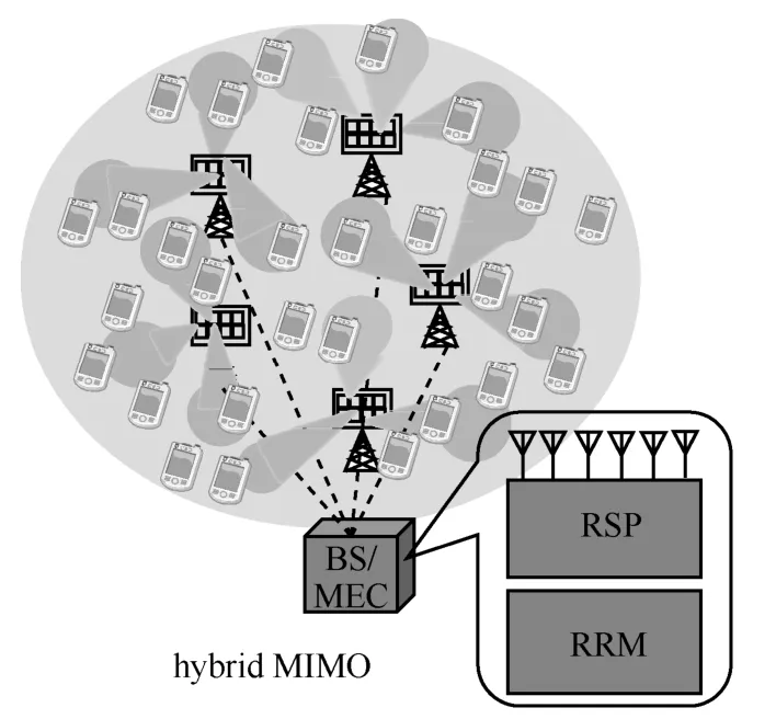
Fig.4 Hybrid structure of large-scale MIMO
B.Cluster-wise MIMO
The computational complexity of large-scale MIMO is prohibitively high since a large number of distributed antennas are involved to accommodate a large number of users in a BS cell (see Fig.5).An effective approach for solving this complexity problem is to form user clusters (or user-centric virtual cells)[8-10].As illustrated in Fig.6,each user cluster(user-centric virtual cell) consists of relatively small number of neighboring users and is serviced by multiple distributed antennas (cluster-antenna association).Therefore,the cluster-wise MIMO can perform in parallel instead of performing single large-scale MIMO.
Assuming minimum mean square error (MMSE)or zero-forcing (ZF) based MIMO multiplexing ofnusers by usingnantennas,a matrix inversion with complexity order ofO(n3) is necessary[11].If we introduce a clustering algorithm to formmclusters,the complexity order of MIMO multiplexing can be reduced tomtimesO((n/m)3),which is much lower than them=1 case (no clustering).Furthermore,MMSE or ZF based MIMO multiplexing weight matrix needs to be updated every few milliseconds in order to track against time-varying fading.On the other hand,the complexity order of clustering is not that much because clustering can be carried out based on users’locations and hence,the cluster formation could be updated every few minutes.Therefore,the computational complexity required for clustering becomes much lower than MIMO multiplexing.

Fig.5 Large-scale MIMO

Fig.6 Cluster-wise MIMO
C.Distributed RRM
Distributed RRM,which performs RRM in a distributed manner at each BS,enables possible highly scalable and flexible deployment of the ultra-densification of RAN,see Fig.7.However,some users in a cell-edge area experience strong inter-cell interference and the communication quality may degrade.Hence,mitigating the inter-cell interference is necessary,which can be achieved by interference coordination between neighbor BSs.Also,there exists the inter-cluster-interference within each BS cell.The eIC to mitigate the inter-cell interference between neighboring BSs as well as the inter-cluster interference in each BS is the key technical issue to realize distributed MIMO based ultra-dense RAN.
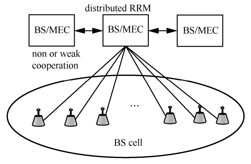
Fig.7 Distributed RRM
D.C/U-plane split
Before performing cluster-wise MIMO to transmit user data (or U-plane data),control data (or C-plane data) transmission (e.g.system information,sync data,etc.) for all of users in a BS cell is necessary.This can be done efficiently by applying what is called C/U-plane split[12].As illustrated in Fig.8,C-plane data is transmitted (or received) simultaneously by activating all of distributed antennas using the same radio resource (i.e.,without forming clusters).By doing so,avirtual single BS antennais formed.A richer multipath channel than using a single antenna is created between each user and BS.The mobile fronthaul timing control is necessary so as to keep the propagation time delays within the guard interval of OFDM based signal waveforms.A good advantage of thisvirtual single BS antennaconcept is that the link blockage due to obstacles can be avoided as well as achieving the frequency diversity effect and then,highly reliable C-plane data transmission is achieved.
Thevirtual single BS antennaconcept has advantages not only in C-plane data transmission but also in U-plane data transmission.Some use cases are shown below.An inherent nature of a wide range of user mobility is problematic when user clustering is applied.For high mobility users,frequent cluster re-formation and antenna re-selection may happen.Increasing the C-plane data traffic reduces the capacity of U-plane data transmission.If U-plane data transmission for high mobility users is done throughvirtual singleBS antenna,neither cluster re-formation nor antenna re-selection is necessary.Another possible use case is the random access of low-power IoT devices.Random access data is received with a higher signal level by distributed antennas closer to each IoT device.By once forming static antenna clusters,random access data from IoT devices located in each antenna cluster area can be received by distributed antennas belonging to the corresponding antenna cluster.Consequently,good collision avoidance or multi-access interference (MAI) suppression is achieved.
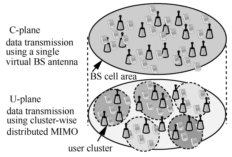
Fig.8 C/U-plane split
III Enhanced interference coordination(eIC)
Increasing the number of user clusters degrades the link capacity due to increasing inter-cluster interference.To remedy this capacity degradation, eIC is introduced.The steps in the eIC procedure are illustrated in Fig.9.Firstly,classifying all users into two groups,i.e.including inner-cell and cell-edge user groups,based on the statistical analysis of measured inter-cell interference level.After user classification,multi-layered clustering and cluster-antenna association are carried out.Since cell-edge users are sparsely distributed,they are grouped into the bottom layer.Thirdly,scheduling is done layer by layer to assign the communication opportunity to clusters in order.Finally,cluster-wise MIMO is done,which employs multi-user multiplexing for inner-cell user group and spatial diversity for cell-edge user group.Updating period of multi-layered clustering could be a several 10 seconds order while that of layer-by-layer scheduling could be a several 10 ms order.
A.Multi-layered clustering
Neighborhood users clustered together give strong interference to each other.K-means algorithm is one of the well-known clustering algorithms[13].For detailed procedure of multi-layered clustering,refer to Ref.[14].Fig.10(a) shows an example of 64 user clusters performed by the K-means algorithm in an isolated square-shaped BS-cell area,where the number of distributed antennas is 128 and the number of users is 128.From Fig.10(a) we can see that the neighboring clusters are close to each other,which will incur strong inter-cluster interference when all clusters are given simultaneously the communication opportunity using the same radio resource and thereby degrade the communication quality.To mitigate this problem,user clusters are separated into different layers to keep inter-cluster distance in each layer longer than the interference-offset-distance (IOD),thereby satisfying the acceptable interference level which depends on the QoS requirement.Specifically,the number of layers is determined by the user distribution and the value of IOD.Fig.10(b) shows an example of the multi-layered clustering,when assumes the IOD is 2R(here,Ris half the average distance between two neighboring clusters),64 clusters can be separated into 3 different layers.To mitigate the scheduling loss,the same cluster is assigned to multiple layers as long as the IOD of 2Ris satisfied.So far,we have considered the inner-cell users only.As mentioned earlier,cell-edge users are grouped into the bottom layer for the small number and sparse distribution,as illustrated in Fig.10(b).After multi-layered clustering,antennas selection for each cluster (called the cluster-antenna association) is done to perform cluster-wise MIMO by taking into account the inter-cluster interference in the same layer.

Fig.9 eIC procedure

Fig.10 Multi-layered clustering
B.Layer-by-layer scheduling
Layer-by-layer scheduling is necessary to give different layers the communication opportunity in turn for guaranteeing the orthogonality among them,as illustrated in Fig.11.For each layer,all clusters in it access the communication opportunity using the same radio resource simultaneously.Time-domain scheduling and frequency-domain scheduling are two types of layer-by-layer scheduling.In the time-domain scheduling,the total scheduling time interval is divided into a number of time slots,and the number of time slots is equal to the number of layers and each time slot is assigned to a different layer.Different from time-domain scheduling,in the frequency-domain scheduling,the total available bandwidth is divided into a number of resource blocks,the number of which is equal to that of layers and each resource block is assigned to a different layer.Specially,all layers can obtain the communication opportunity at the same time in the frequency-domain scheduling,which is appropriate particularly to low-latency communication services like URLLC.

Fig.11 Layer-by-layer scheduling
C.Radio resource assignment
When adopts the distributed RRM,the predominant interference which cell-edge users suffer is from those in the neighboring BS cells.To handle this inter-cell interference problem,a fully distributed algorithm (called CS-based FFR) is applied,which combines the fractional frequency reuse (FFR)[15-16]and the channel segregation (CS)[16].
The CS-based FFR is illustrated in Fig.12.Fig.12 (a) shows a FFR using a reuse factor of 3,which means that the total available bandwidth is divided into 3 fractional bands.The radio resource assignment procedure is shown in Fig.12 (b) together with inner-cell users’ radio resource assignment.The CS assigns different fractional bands in a fully distributed manner to cell-edge areas of immediately neighboring BSs.Each cell-edge user can select the best fractional band based on the signal-to-interference ratio (SIR) on other fractional bands in addition to the one assigned by the CS to improve its throughput.Furthermore,single-user MIMO spatial diversity can mitigate the inter-cell interference sufficiently.
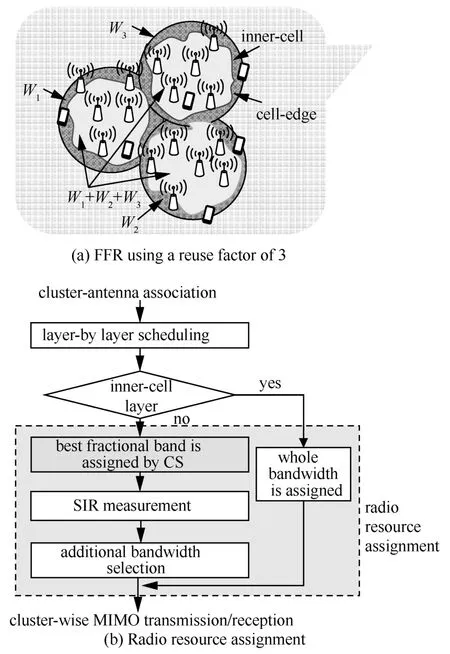
Fig.12 CS-based FFR
D.Cluster-wise MIMO
Cluster-wise MIMO can be either spatial multiplexing or spatial diversity.The former is known as multi-user MIMO[17]and has been regarded as an indispensable technique for highly improving the spectrum efficiency.Meanwhile,spatial diversity[18]still remains an vital countermeasure against multipath fading.The spatial multiplexing can be applied to simultaneously accommodate users in each user cluster who experience a strong inter-cluster interference rather than a strong inter-cell interference.On the other hand,the spatial diversity is applied to cell-edge cluster users who are relatively sparsely distributed (hence,multi-user signal processing is not necessary) and experience strong inter-cell interference.
As the waveform design,either OFDM or single-carrier (SC) waveform can be used as adopted in 4G systems.OFDM waveform has a high peak-to-average power ratio (PAPR) and hence,the power efficiency of its transmit power amplifier becomes problematic when using the mmWave band.Although short range communication alleviates the high PAPR problem to some extent,the SC waveform will remain useful in 5G advanced systems.
A simple way of alleviating inter-user and inter-antenna interference is ZF precoding at the BS transmitter.The authors in Ref.[19-20]presented a framework for ZF based multi-user MIMO coordinated transmit-receive beamforming,which requires computationally expensive iterative algorithms.Assuming time division duplex (TDD),we recently proposed a ZF-based multi-user MIMO coordinated with user-wise maximal-ratio transmitting and combining(MRTC) diversity[21].Another promising multi-user multiplexing scheme is the MMSE based multi-user filtering combined with singular value decomposition(SVD) called multi-user MMSE-SVD[22-23].Either space-time block-coded transmit diversity (STBC-TD)or selective MRTC can be a good candidate for single-user spatial diversity scheme for cell-edge users.In the case of SC,they need to be jointly used with frequency-domain equalization (FDE) to cope with the severe frequency-selective fading encountered in broadband SC transmissions[24-25].

Fig.13 The transmitter and receiver structure for cluster-wise MIMO
OFDM and SC with FDE requires accurate channel state information (CSI).When TDD is adopted,the downlink CSI at BS can be obtained by channel reciprocity without feedback.In detail,the uplink CSI required by BS for uplink signal reception can be directly reused for downlink signal transmission.Hence,sophisticated FDE for transmission/reception can be equipped at BS when TDD is adopted.The transmitter and receiver structures for cluster-wise MIMO assuming OFDM based downlink transmission is illustrated in Fig.13.
IV Downlink capacity evaluation
In Sect.II,a concept of ultra-dense RAN based on distributed MIMO architecture is presented and then,eIC is described,which tries to effectively mitigate the inter-cluster interference and inter-cell interference by using multi-layered clustering and CS-based FFR,respectively.Here,the evaluation of inter-cluster interference mitigation by multi-layered clustering is presented.
The downlink capacity achievable by multi-layered clustering is evaluated by computer simulation.Here only the inner-cell users are considered.Simulation parameter settings are shown in Table I.In detail,the number of distributed antennas is 128 and the number of users is 128.Each user is equipped with single antenna and is positioned in an isolated,single square-shaped BS cell randomly.All users are considered as an inner-cell user.Specially,an important design parameter is the number of clusters.Here,two cases are considered:one is 32-cluster case (4 users per cluster on average) and the other is 64-cluster case(2 users per cluster on average).User clusters are formed using the K-means algorithm and then,they are separated into multiple layers assuming IOD of 2R.The number of layers depends on the users’ locations.According to our simulation,it was found that the average number of layers is 3 for both 32-cluster and 64-cluster cases.After multi-layered clustering,the cluster-antenna association is done on each layer for assigning the best distributed antenna to each user in an ascending order of user-distributed antenna distance (equivalently in an ascending order of path loss);the remaining antennas on each layer are assigned to users based on the shortest distance criterion.Then,cluster-wise MIMO using multi-user MMSE-SVD[23-24]is performed in parallel in all clusters on each layer.The normalized transmit signal energy per user-to-noise power spectrum density ratiois set to 0 dB (i.e.,the downlink transmit power assigned to each user is set so as to make the receivedbecome 0 dB when the transmit and receive antennas distance is equal to that between the center and vertex of BS-cell).Therefore,the MIMO channel is interference-limited.
The downlink sum capacity achievable with cluster-wise MIMO was evaluated by using the Shannon formula.To obtain the downlink sum capacity distribution,the simulation changes user location 100 times,shadows loss by 10 times,and changes the Rayleigh fading gain by 10 times (the total number of propagation environment changes is 10 000).The cumulative distribution function of downlink sum capacity is shown in Fig.14.As the number of clusters increases from 32 to 64,the achievable link capacity degrades due to the increased inter-cluster interference.However,the capacity degradation is smaller for multi-layered clustering than for non-layered clustering.This clearly shows effectiveness of the proposed multi-layered clustering.Also plotted for comparison are the sum capacities achievable with nonlayered clustering (i.e.,single layer),random clustering (i.e.,64 pairs of 2 users and 32 pairs of 4 users are randomly formed),and user-wise single-input single-output (SISO) performed in parallel.It can be seen from Fig.14 that multi-layered clustering can achieve highest link capacity among user-wise SISO,random clustering,non-layered clustering,and multi-layered clustering.
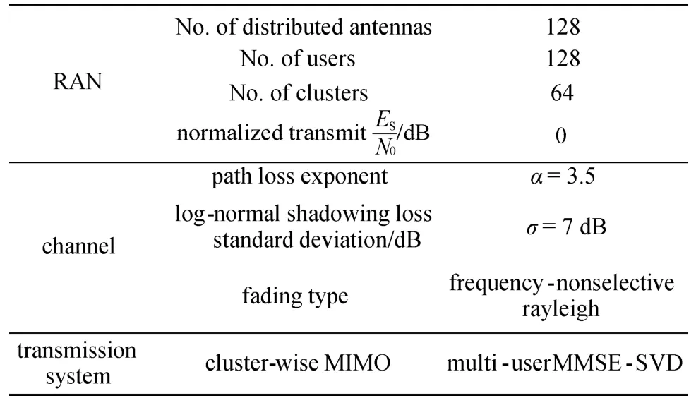
TABLE I SIMULATION SETTING

Fig.14 Downlink sum capacity
V Conclusions
Ultra-densification of RAN is inevitable to handle ever-increasing mobile data traffic in 5G era.Severe interference problem arises as a result of dense reusing the same radio resource.Furthermore,radio link interruption may be frequently occurred in mmWave communication due to obstacles.An important technical issue for realizing highly reliable communication in such a harsh radio communication condition is the interference coordination.In this paper,a possible architecture of distributed MIMO based ultra-dense RAN was presented.Then,an eIC composed of multi-layered clustering and CS-based FFR was presented.Finally,some computer simulation results on the achievable link capacity was presented to show an encouraging capability of distributed MIMO based ultra-dense RAN using eIC.
There are many open issues related to ultra-dense RAN.Some of them are listed below.
a) Achieving a good tradeoff between computational complexity and link capacity when clustering is used:it was shown in this paper that the multi-layered clustering can effectively mitigate the link capacity degradation due to increased inter-cluster interference produced by increasing the number of clusters.There may be other approaches to more effectively alleviate the inter-cluster interference and to achieve a good tradeoff between computational complexity and link capacity.
b) User clustering when taking into account the user mobility:clustering can be carried out based on users’ locations and hence,the cluster formation could be updated every few minutes.However,in reality,a wide variety of user mobility may become problematic.It may be necessary to categorize users into several groups according to their travelling speeds,e.g.stationary,low-speed,and high-speed user groups,etc.,and then,carry out clustering for each category.How to incorporate the user mobility into clustering is an interesting open issue.
c) Optimization of CS-based FFR:the number of fractional bands is an important design parameter of CS-based FFR.Increasing the number of fractional bands can sufficiently mitigate the inter-cell interference,but in return,the link capacity reduces since narrower bandwidth is assigned to cell-edge users.Furthermore,the inter-cell interference is strongly affected by multi-cell structure,user distribution over an entire service area,and propagation parameters.By taking into account them,the number of fractional bands needs to be optimized for performance evaluation of eIC.
d) Ultra-dense RAN architecture having high deployment flexibility and scalability:one approach is based on distributed MIMO,which was presented in this paper.Another approach is based on localized multi-user MIMO (or beam forming).The achievable link capacity is strongly affected by the propagation environment.It may be interesting to compare distributed MIMO and localized MIMO-based ultra-dense RAN architectures in terms of link capacity in various types of propagation environment (e.g.,line-of-sight and non line-of-sight).
Besides the above open issues,there are some other interesting research topics.In cluster-wise MIMO,we have tried to optimize the transmission system for the given radio propagation environment.But now it is time to optimize the whole transmission system including the radio propagation environment,by introducing e.g.intelligent reflecting surface (IRS)[26].A combination of cluster-wise MIMO and IRS will be an interesting research topic even in 5G era.Recently,research into wireless AI towards 6G has been intensified[2-4].Wireless AI will become a very helpful tool to optimally manage wireless networks.Ultra-dense RAN would be AI-driven.In 6G systems,THz band will be utilized to provide ultra-high rate communication services like enhanced eMBB+URLLC.Restructuring of RAN in a mixed utilization of different frequency bands of microwave,mmWave,and THz is an interesting technical issue.Another important technical issue is to develop a low cost,low latency optical mobile fronthaul.