Numerical Study on Aerodynamic Performance of CK Drone Aircraft Air Inlet in Maneuvering Flight
2020-11-25,,,*
,,,*
1.Key Laboratory of Advanced Technology for Small and Medium-Sized UAV,Ministry of Industry and Information Technology,Nanjing University of Aeronautics and Astronautics,Nanjing 210016,P.R.China;2.College of Energy and Power Engineering,Nanjing University of Aeronautics and Astronautics,Nanjing 210016,P.R.China
(Received 10 June 2020;revised 20 July 2020;accepted 1 September 2020)
Abstract:In view of the engineering background that CK drone aircraft needs modification and upgrading to improve its maneuvering performance,numerical research and analysis of air inlet aerodynamic performance are carried out.Firstly,based on the introduction of the theoretical knowledge involved in aircraft maneuvering flight,parameters such as aircraft attitude and engine mass flow etc.required for the aerodynamic performance calculation of CK drone aircraft air inlet are determined.By analyzing the test data of WP6 engine inlet distortion simulation board,the typical indexes are extracted as the basis for evaluating the air inlet performance of CK drone aircraft.Then,the aerodynamic characteristics of the inlet of CK drone aircraft under different maneuvering conditions are numerically studied,and the total pressure recovery coefficient and pressure distortion index of the outlet section are obtained.Several conclusions and suggestions are formed after the study.When CK drone aircraft flies at positive angle of attack,the inlet has good aerodynamic characteristics,which can meet the requirements of engine intake during high maneuverable flight.In the flight of negative angle of attack,the total pressure loss and pressure distortion at the outlet section of air inlet increase sharply,which cannot guarantee the stable working of the engine.On the premise that the aircraft attitude is satisfied,CK drone aircraft can use three engine thrust states of“Rated”,“Modified rated”and“Maximum”for high maneuverable flight.
Key words:CK drone aircraft;high maneuvering flight;suspended nacelle inlet;total pressure recovery coefficient;pressure distortion index
0 Introduction
CK drone aircraft,a high subsonic large entity drone,is developed by Nanjing University of Aeronautics & Astronautics(NUAA,formerly known as Nanjing College of Aeronautics)in 1968.After more than half a century of development,the aircraft has formed series products such as CK1 drone[1],CK3 drone[2]and CK2 unmanned aerial vehicle(UAV)[3],respectively for high altitude,low altitude,high maneuverability,hedgehop,rocket-propelled,navy,air force,and so on.The drone has played an important role in China’s nuclear testing,missile identification,and fighter appraisal.Even now,it still has an irreplaceable position in China.
CK drone aircraft is a very mature aircraft platform.At present,more than 300 aircraft have been used in NUAA,and a large number of flight tests and verification have been carried out.The maximum flight altitude is more than 14 000 m,the maximum flight speed is about 900 km/h,and the maximum stable normal overload is about 3g—4g[1].Due to the development of technology and upgrading of airborne equipment,Research Institute of Unmanned Aircraft of NUAA started the modification work of CK5 drone aircraft in 2016[4].One of goals is to increase its maneuvering performance from the stable normal overload of 3g—4gto 5g—6g.Considering the modification designing cost and operation cost of the aircraft,the CK5 drone aircraft basically follows the original aerodynamic shape and power device.
The CK drone aircraft uses a modified retired WP6 engine as the power device,and the engine is suspended under the fuselage,as shown in Fig.1[5].The main work of engine modification is to remove the original after-burned system,shorten the nozzle and change the adjustable nozzle to fixed nozzle.After the modification,the service requirements and working reliability of the engine are similar to the original engine,and the thrust is slightly improved[6].

Fig.1 CK1 drone aircraft[5]
Due to the improvement of maneuverability,the work to be demonstrated by the power system mainly includes two parts:One is whether the engine can withstand such overloads,the other is whether the inlet can provide qualified intake conditions for the engine.The normal overload of 7gwas pulled out in the test flight for the J-6 fighter with the WP6 engine[7].This shows that the optimized modified WP6 engine can meet the overload requirements of CK5 drone aircraft.Therefore,the next important problem is to study whether the inlet can meet the requirements of the engine in maneuvering flight.
There are many researches on the aerodynamic performance of air inlet at home and abroad.According to the published papers,the research on basic research[8-10],new S-shaped inlet and diverterless supesonic inlet(DSI)[11-16],as well as inlet studies of fighter[17-19]and passenger planes[20]account for the majority.Structurally similar to CK drone aircraft inlet,the passenger plane has a suspended nacelle inlet,but the front end of the air inlet is generally beyond the wing to eliminate the effects of the wing,as shown in Fig.2.Similar to CK drone aircraft,J-10 fighter has an inlet which is installed near the fuselage.However,the air inlet of fighters has enough length for rectification to eliminate the impact of the fuselage on the air flow,as shown in Fig.3.So far,no public research results on CK drone aircraft inlet have been searched.

Fig.2 Passenger plane C919

Fig.3 J-10 fighter
Due to the long flight test time,high cost and high risk,and with the improvement of computer performance and the development of technology in the field of domestic inlet research,numerical study has become a highly reliable method.The inlet of a new UAV[21]developed by the Research Institute of Unmanned Aircraft of NUAA is also designed based on a large number of numerical studies and supplemented by a small amount of air blowing test modification.
To preliminarily prove whether the inlet can meet the technical requirements of CK5 with a small investment,and provide a technical reference for the low-cost modification of CK drone aircraft,this paper conducts a numerical study on the inlet performance of CK drone aircraft in maneuvering flight.
1 Theoretical Basis
This section introduces the theoretical basis related to aircraft maneuverability,engine operation,and inlet aerodynamic performance.
1.1 Basic assumptions
The numerical study in this paper is based on the following basic assumptions:
(1)The front flow for inlet is dry air.
(2)The influence of the sudden wind is not considered.
(3)The research is limited to the flight state that CK drone aircraft may face and the corresponding engine thrust states.
1.2 Maneuver overload and attitude of aircraft
CK drone aircraft realizes the simulation of maneuvering characteristics through horizontal steady hovering.According to the basic knowledge of flight mechanics,the corresponding relationship between roll angle and overload of drone aircraft is

whereγandnyare roll angle and overload.The roll angles corresponding to typical overload values shown in Table 1 can be obtained by mathematical calculation.

Table 1 Aircraft overload versus roll angle
In the process of hovering maneuver,although the aircraft has a roll angle,the roll angle does not affect the inlet flow.Nevertheless,in the process of establishing the roll angle,the airflow has the sideslip angle relative to the aircraft.The larger the roll angle is established in the same time,the larger the sideslip angle of flight will be.
As long as the aircraft has a roll angle,the lift component used to bear the weight of the aircraft will gradually reduce.At this time,in order to maintain the height,the aircraft must improve the wing lift,generally need to increase aircraft flight angle of attack,or use large thrust state to improve the flight speed.
Therefore,aircraft attitude involved in aerodynamic performance calculation is mainly flight angle of attack and sideslip angle.According to the general aerodynamic analysis,the maximum sideslip angle of CK5 drone aircraft faces during the establishment of 6goverload is not more than 10°,and the maximum flight angle of attack required for hovering is not more than 10°.
1.3 Engine state used by CK drone aircraft
The improved WP6 engine is equipped with CK drone aircraft to provide“Maximum”,“Modified rated”,“Rated”,“Cruise 1”,“Cruise 2”,“Cruise 3”and“Idle”for flight[1].During the usage,the aircraft can adjust the thrust value of each state according to flight requirements,while the change of engine thrust is realized through the change of throttle status,and different throttle status corresponds to different engine speed and air mass flow[22].Table 2 shows the thrust state adopted by CK5 drone aircraft.In Table 2,Fis the static thrust under standard state,nthe converted rotational speed,andWacorthe converted air flow.

Table 2 Engine states for CK5 drone aircraft
In Table 2,“Idle”is intended to be used for drone aircraft sliding,“Cruise 1”,“Cruise 2”and“Cruise 3”are intended to be used for drone aircraft cruising under different requirements,“Rated”and“Modified rated”are mainly used for drone aircraft climbing and maneuver hovering,and“Maximum”is used for climbing and hovering for short time under special cases.
1.4 Engine flow conversion
Because the air becomes lean with altitude,the actual air mass flow(physical flow)of an engine at the same speed decreases gradually.The physical flow of the engine can be converted by[23]

whereWais the physical mass flow rate,the total temperature of the incoming flow,andthe total pressure of the incoming flow.andcan be calculated by[24]

whereTis the static temperature of the incoming flow,andpthe static pressure of the incoming flow.k=1.4 for dry air,andMais the local Mach number

whereu0is the flight speed,andcthe sound speed at the corresponding altitude[24]

whereR=287.06 J/(kg·K)for air.
1.5 Total pressure recovery coefficient for air inlet
The total pressure recovery coefficientσis an important indicator of the aerodynamic performance of the inlet,which reflects the total pressure loss in the inlet.It indicates the perfection of the stagnation process of the air flow in the inlet,and has a significant impact on the engine performance.Generally speaking,a 1% decrease in the mean total pressure recovery coefficient of the inlet can cause about 1.25% decrease in engine thrust[23].
The local total pressure recovery coefficient of the inlet is defined as the ratio of the local total pressure at the outlet section of the air inlet(the engine inlet section)to the incoming flow total pressure[25]

Generally,the average total pressure recovery coefficient of the inlet can be used to preliminarily judge the aerodynamic performance of the inlet,which is defined as the ratio of the average total pressure of the inlet outlet section to the total pressure of the incoming flow[25]

1.6 Distortion index for air inlet
The distortion index is another important index reflecting the aerodynamic performance of the inlet,which directly affects the working stability of the engine.It refers to the uneven degree and pulsation degree of airflow on the inlet outlet section(engine inlet section).The higher the distortion index is,the more likely it will cause the unstable working or even flameout of the engine.
According to the flow parameters,it can be classified into pressure distortion,temperature distortion and velocity distortion(namely cyclone).According to the characteristics of the spatial distribution of airflow parameters,it can be classified into radial distortion and circumferential distortion.According to whether the distortion changes with time,it can be divided into steady distortion and dynamic distortion.
In the matching of inlet and engine,the most important distortion is pressure distortion,which generally refers to the total pressure distortion.The influence of the circumferential distortion on the engine stability is much greater than that of the radial distortion,so the circumferential distortion of the total pressure is generally concerned.
Distortion indexDCθis commonly used to reflect the uneven distribution degree of total pressure in the flow field of the inlet outlet section.It is defined as[25]

1.7 Matching requirements for WP6 engine and air inlet
The matching of inlet and engine mainly refers to the matching of flow,that is,in each flight attitude and engine operation state,the inlet should ensure enough air flow for the engine,and the distortion of the flow in outlet section should meet the requirement of engine.
CK drone aircraft adopts a subsonic nacelle inlet,and the flow matching for inlet and engine can be automatically matched through the flow coefficient.Therefore,the key point of matching is whether the flow distortion in the inlet outlet section meets the requirements of engine.
Since WP6 engine is a product of the 1950s,all the J-6 fighters in which this engine used have been retired,and it is difficult to find the specific index requirements of inlet distortion in the open literature.This paper refers to the technical indicators provided in“Inlet Distorted Flow Field Simulation Plate Experiment”in Ref.[25]as the evaluation basis.
In accordance with the spirit of the J-8II fighter Inlet/Engine Matching Conference held in Beijing in 1983,the 204 Research Office of NUAA accepted the commission from 601 Research Institute.Firstly,hundreds of tests on a small test device were carried out,and three simulation plates required were obtained.Then,an engine test rig was built,the inlet was matched,and three simulated plates were verified by WP6 engine.Three typical test results are summarized in Table 3.
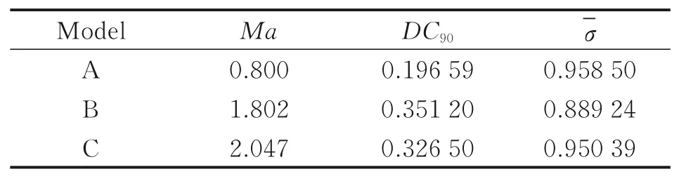
Table 3 Ground test parameters for WP6 engine and air inlet matching
The tests show that the engine can work normally without surge or flameout when the distortion simulation plate is installed in the inlet.The maximum inlet distortion index obtained in the test is|DC90|=0.351 2,which indicates that WP6 engine can work stably as long as|DC90|≤0.351 2 in the engine inlet section.
2 Calculation Model and Method
2.1 Physical model
Fig.4 shows the 3-D diagram of the front part of fuselage of the CK drone aircraft.Due to the subsonic flight of the aircraft,the model simplifies and removes the wings and the rear section.The origin point of the model is located at the vertex of the nose,and the maximum diameter of the fuselage is 550 mm.The inlet section of the nacelle inlet under the fuselage is 1 727 mm away from the nose vertex,and the inlet center point coordinate is(1 727,-865,0).The inlet radius is 300 mm,and the total length of the inlet is 640 mm.The center point coordinate of engine inlet is(2 367,-865,0),and its radius is 297.5 mm.The faring cone radius is 100 mm,and its length is 200 mm.

Fig.4 3-D model of CK drone aircraft(Part of forward fuselage)
2.2 Computing grid
Fig.5 shows the 3-D computing domain established for the above model.The forward distance is 9 m,and the height and width of the far field are both about 12.7 m.

Fig.5 Schematic of computational domain
Multi-block structured grids in the computing domain is generated with ICEM software,and the total number of grid cells is about 5.7 million.The mesh is refined near the wall.The distance of the grid near the wall is about 0.1 mm.Fig.6 shows the grid of the fuselage and the inlet surface,and Fig.7 shows the grid of the engine faring cone and the inlet cross section.

Fig.6 Grid of fuselage and air inlet

Fig.7 Grid of inlet section and faring cone of engine
2.3 Calculation method
FLUENT software is used to calculate the air flow field,and the implicit solver based on density is used to solve the continuity equation,momentum equation,energy equation and turbulence equation.Thek-ωSST model is used for turbulence calculation.Since the computation is developed on the traditional computational fluid dynamics method,the mathematical equations and parameters are not introduced here.
The total pressure recovery coefficientσof the inlet,the average total pressure recovery coefficientand the pressure distortion indexDC90of the outlet section are all calculated by the self-developed program.This program reads the flow parameters of the inlet outlet section which are obtained from FLUENT.Starting from the horizontal line,i.e.,the starting edge,every 90° sector is established when the starting edge is rotated by 10°,and the average total pressure of these 36 sectors is calculated.Finally,DC90is calculated with the minimum average total pressure.
2.4 Boundary conditions
The solid boundary in the model included fuselage,inlet,engine nacelle skin and saddle-type transitional section,as well as engine faring cone.These solid surfaces are all set as stationary wall boundary with surface roughness constant of 0.5.The near-wall area is assumed to be non-slip boundary.Adiabatic boundary is used for solid wall surface.
The far field boundary is used upstream and around the drone aircraft,the ambient pressure and temperature are determined according to the flight altitude,and the incoming flow velocity is calculated according to the flight velocity and the aircraft attitude angle.
The outlet section of the air inlet adopts the pressure outlet boundary.The air flow is calculated by Eq.(2)and the total temperature is calculated by Eq.(3).
The outlet of the calculation domain adopts the pressure outlet boundary,and the static pressure is determined according to the flight altitude,and then the total temperature is calculated according to Eq.(3).
3 Results and Analysis
3.1 Aerodynamic performance of CK drone aircraft air inlet
CK5 drone aircraft intends to provide target by maneuvering hovering at an altitude of 5 000 m with a flight speed of about 240 m/s.The above method is used to calculate the local total pressure recovery coefficient,the average total pressure recovery coefficient and the pressure distortion index under different engine states and aircraft attitudes.The results are shown in Table 4.It shows that the average total pressure recovery coefficients of Cases 14,20 and 22 are low,which will cause a large thrust loss.The pressure distortion indexes of the corresponding cases also exceed the scope of test verification in Section 1.7,which may cause unstable engine work.The common feature of these three cases is that they have large negative attack angle and sideslip angle at the same time.It corresponds to the hovering maneuver while the aircraft descends,which does not exist in the flight mission planning of CK target aircraft.In other cases,the average total pressure recovery coefficients are bigger than 0.992,and the pressure distortion indexDC90of the outlet section can meet the requirements for the stable working of the engine,indicating that the air inlet can meet the flight requirements of CK5 drone aircraft.The detailed aerodynamic characteristics of the inlet are analyzed in the following.

Table 4 Aerodynamic performance of CK drone aircraft air inlet
3.2 Characteristics versus engine mass flow
The flight state of the drone aircraft is related to the thrust state of the engine,while the thrust of the WP6 engine is corresponding to its air mass flow.This section analyzes the inlet characteristics versus different engine states.
In Table 4,the engine flow of Cases 1—5 corresponds to the thrust states of the five engines states used by CK drone aircraft,namely“Maximum”,“Modified rated”,“Rated”,“Cruise 1”and“Cruise 2”,respectively.The angle of attack and sideslip angle are both set as 6°.It can be seen that,with the decrease of engine air mass flow,the average total pressure recovery coefficient of CK drone aircraft inlet gradually increases,and the coefficient of“Maximum”state is the smallest,which is 0.997 2.The distortion index of the outlet section of the above four states are the same,while the distortion index of the“Cruise 2”state with the smallest air mass flow is the biggest,which is 0.015 6.This indicates that under these operation states of the engine,the air inlet can completely meet the requirements CK drone aircraft.
As“Maximum”of WP6 engine is not allowed to be used for more than 6 min[22],this state is not suitable for long time maneuvers hovering.Since the thrust of“Cruise 2”and“Cruise 1”are both too small,they are not enough to maintain hover maneuver flight speed and height.Therefore,only two states of“Modified rated”and“Rated”intended to be used for drone maneuver are analyzed in the following part.
3.3 Characteristics versus angle of attack
It can be seen from the calculation data of Cases 9—13 in Table 4 that the inlet with negative angle of attack has the worst characteristics.However,even under the unfavorable condition of 6° sideslip angle,the average total pressure recovery coefficient is still as high as 0.992 2,and the pressure distortion index is 0.279 3,which is also within the range of stable working of the engine.The performance of other cases with positive angle of attack is better.In the flight with 0° sideslip angle(Cases 6—8,Cases 17—19),the inlet aerodynamic performance is perfect.Even under the process of establishing the roll angle with a sideslip angle of 10°,as long as the angle of attack is positive(Cases 15,16 and Cases 23,24),the total pressure loss(thrust loss)of the inlet is very small,and the flow distortion can fully meet the requirements of engine.This shows that the inlet efficiency of CK drone aircraft is very high,which can fully meet the requirements of straight flight(fixed altitude,climb,slide)and spiral flight(fixed altitude and spiral climb).
Fig.8 shows the streamline under three typical angles of attack,i.e.,Cases 9,10,13.It can be seen that,when the angle of attackα=-10°appears,flow separation occurs inside the upper lip of the inlet and outside the lower lip.The flow velocity in the separation area and the total pressure are all low,which is a low energy area.The separation in the air inlet will increase the total pressure distortion at the outlet section.If the distortion index does not exceed the allowable value of the engine,it will not affect the normal working of the engine,but will reduce the total pressure recovery coefficient.When the angle of attack isα=6° andα=10°,there is no separation in the flow field,and the flow quality is good.

Fig.8 Mach number and streamline on symmetric middle surface at different angles of attack
The pressure distortion index distribution of Cases 9,10,13 are shown in Fig.9.From the flow characteristics,we can see that CK drone adopts a nacelle inlet suspended under the fuselage,so there is no occlusion right ahead.Under the positive angle of attack,the incoming flow of air inlet is not affected by the nose of the fuselage.In addition,the aerodynamic characteristics of the inlet lip is good,and there is no flow separation inside the air inlet.Therefore,the pressure distortion index is relatively small,and the total pressure recovery coefficient is relatively high.But in a negative angle of attack,due to the washing function of the flow under the nose,the boundary layer on the fuselage is blown into the inlet section of the air inlet.At the same time,after the air flow passes the nose,the streamline direction in front of the inlet also changes.All these factors lead to the flow separation in the air inlet,which increases the pressure distortion,and reduces the total pressure recovery coefficient.

Fig.9 Distribution of total pressure recovery coefficient on outlet section at different angles of attack
3.4 Characteristics versus sideslip angle
As can be seen from Table 4,in Cases 2,3,7,15,18,23 with positive angles of attack,the inlet performance slightly decreases with the increase of sideslip angle.The total pressure loss(thrust loss)is not so large,and the pressure distortion is within the requirement range in the engine stable working.But in the angle of attack of-10°(Cases 6,9,14,17,20,22),the large sideslip angle not only leads to a sharp increase in the total pressure loss(thrust loss),but also the total pressure distortion soon goes out of the requirement range of the engine stable working.This indicates that the CK drone aircraft cannot establish large roll angles when flying at a large negative angle of attack.
For negative angle of attack flight with severe total pressure loss and pressure distortion,the local pressure distortion index distribution of its outlet section is shown in Fig.10.It can be seen that with the increase of sideslip angle,not only the total pressure recovery coefficient drops sharply,but also its influence domain expands sharply,and the corresponding pressure distortion index also increases sharply.Combined with the flow characteristics of Case 9 in the previous section,it shows that when there is a sideslip angle,the downwash airflow of the nose is more likely to cause a wide range of airflow separation in the inlet,which will soon cause the flow distortion to go out of the range of requirements in engine stable working.
4 Conclusions
The inlet aerodynamic performance of CK drone aircraft in maneuvering flight was numerically studied,providing a technical reference for CK5 drone aircraft maneuverability upgrade.The research results are as follows:
(1)When CK drone aircraft flies at positive angle of attack,the incoming flow has good quality.Meanwhile,the lip of the inlet has good aerodynamic characteristics.Therefore there is no flow separation in the air inlet,the total pressure recovery coefficient of the inlet is high,and the pressure distortion index is low.So the aircraft can establish large roll angles and perform high maneuverable flights.Under all positive angles of attack(including the combination of positive angles of attack and sideslip angles),the average total pressure recovery coefficient of the inlet is not less than 0.997,and the distortion index is not more than 0.016,which fully meet the stable working requirements of the engine.

Fig.10 Distribution of total pressure recovery coefficient at inlet outlet under different sideslip angles
(2)When CK drone aircraft flies at negative angle of attack,the flow separation occurs inside the inlet due to the influence of the nose downwash flow and boundary layer,and the total pressure recovery coefficient decreases significantly and the distortion index increases sharply.Therefore,it is not recommended to maneuver during flight at negative angle of attack.The worst performance of the air inlet occurs under the combined attitude of the angle of attackα=-10°and the angle of sideslipβ=10°.
(3)When maneuvering at positive angle of attack,the engine may be in two states of“Rated”and“Modified rated”.If the thrust is insufficient,the“Maximum”state can also be used for a short time.
AcknowledgementThis work was supported by the Fundamental Research Funds for the Central Universities(No.56XCA2004806).
AuthorsDr.CAO Guangzhou received the Ph.D.degree in aerospace propulsion theory and engineering from Nanjing University of Aeronautics and Astronautics(NUAA),Nanjing,China,in 2011.Now he is an associate professor in Research Institute of Unmanned Aircraft,NUAA.His current research interests include propulsion technology for UAV and heat and mass transfer technology for aero-engine.Mr.TAN Hongming received the B.S.degree in aircraft design from NUAA,Nanjing,China,in 1994.Now he is an associate professor in Research Institute of Unmanned Aircraft,NUAA.He mainly researches overall design for UAV system and aerodynamic performance study for aircraft.
Author contributionsMr.CAO Guangzhou designed the study,completed the calculation on the flow field for CK aircraft and on the performance for WP6 engine.Dr.LI Bo contributed to the calculation and discussion for air inlet characteristics.Prof.LIANG Shibo contributed to the discussion and revision of the study.Mr.TAN Hongming contributed to the 3-D modeling for CK aircraft and determined the aircraft attitude for maneuverable flight.All authors commented on manuscript draft and approved submission.
Competing interestsThe authors declare no competing interests.
杂志排行

Transactions of Nanjing University of Aeronautics and Astronautics的其它文章
- Progress of Chinese“Dove”and Future Studies on Flight Mechanism of Birds and Application System
- Probabilistic Tolerance Method for Omitting Small Fatigue Loads
- Numerical Study on Influence of Key Parameters of Aerodynamic Characteristics of Shaftless Ducted Rotor
- Uncertain Modal Analysis of Unmanned Aircraft Composite Landing Gear
- An h-Adaptivity DG Method on Locally Curved Tetrahedral Mesh for Solving Compressible Flows
- A Warming Structure for Piezoelectric Stack Working in Cryogenic Temperature