Sliding-mode control for a rolling-missile with input constraints
2020-11-01HUASiyuWANGXugangandZHUYin
HUA Siyu,WANG Xugang,and ZHU Yin
1.The 802 Institute of Shanghai Academy of Space Flight Technology,Shanghai 201100,China;2.School of Energy and Power Engineering,Nanjing University of Science and Technology,Nanjing 210094,China
Abstract:This paper investigates the overload stabilization problem of the rolling-missile subject to parameters uncertainty and actuator saturation.In order to solve this problem,a sliding-mode control(SMC)scheme is technically employed by using the backstepping approach to make the dynamic system stable.In addition,SMC with the tanh-type switching function plays an important role in reducing intrinsic vibration.Furthermore,an auxiliary system(AS)is developed to compensate for nonlinear terms arising from input saturation.Finally,the simulation results provide a solution to demonstrate that the suggested SMC and the AS methodology have advantages of strong tracking capability,anti-interference ability and anti-saturation performance.
Keywords:input constraint,back-stepping approach,sliding mode control(SMC),auxiliary control system.
1.Introduction
In many current and future missions,not only guidance accuracy is needed,but also a control system is required to trace guidance command correctly and rapidly to guarantee expected motion for a rolling-missile.Its oblique tail can provide a rolling-speed that leads to a strong coupling between pitch-channel and yaw-channel motions.Additionally,its aerodynamic coefficients have some uncertainty,and the actuator may be easier to fall into a saturated state,which is an enormous challenge for precision attack missions.
On the one hand,in order to address nonlinear issues on parameters uncertainty,many scholars have done deeply research,and a lot of effective control methods[1–11],such as back-stepping technique, sliding-mode control (SMC), adaptive control and robust control, have been proposed.
Dong et al.[1]presented a switched controller based on a fuzzy logic system for near space vehicles containing unknown disturbances and uncertainties,where total disturbances were compensated by adopting the back-stepping method,and given examples showed the effectiveness and advantages of the proposed control method.Dian et al.[2]utilized an approximator to approximate unknown and nonlinear functions,which guaranteed tracking errors to be ultimately bounded.Jiang et al.[3]proposed an adaptive back-stepping method and SMC for flight attitude of quadrotor UAVs,which stabilized their attitude and had hover flight capabilities under perturbations and external disturbances.For a quadrotor micro aerial vehicle under external perturbations,an adaptive second order SMC was designed by Herman et al.[4],and simulation results showed its feasibility and attractiveness.In[5],for an aircraft with external disturbances,the proposed SMC removed a chattering effect,revealed significant adaptive properties and guaranteed precise constraint fulfillment within a finite time.In[6],for the problem of attitude control of a quad tilt rotor aircraft with unknown external disturbances,a new exponential fast nonsingular terminal sliding surface was proposed,which achieved a good control performance.In[7],a hyperbolic tangent function played a role in vibration reduction in the SMC system.Zhang et al.[8]proposed a global SMC for UAVs against parameter uncertainties and external disturbances,eventually eliminating intrinsic vibration in the SMC scheme.Zheng et al.[9]presented an adaptive backstepping controller to improve performances by more than 80%compared with passive vehicle suspension systems.In[10],using both adaptive sliding surfaces and adaptive controller was able to manage input disturbances with bounded derivatives.In[11],a robust decentralized faulttolerant resilient controller was designed to compensate for both actuator fault and input saturation,and simulation results showed great robustness of the designed control scheme.
On the other hand,actuator saturation as a dominant input nonlinearity often limits system performance and severely leads to its instability[12].As showed in[13],ac-tuator saturation means that output of an actuator is limited to physical constraints,which makes actual output smaller than control input given by the designed controller.As a result,the designed controller loses the ability to adjust control output in time,which makes the control system unstable.In[14],actuator saturation included input magnitude and rate saturation.Input magnitude saturation is the key research in this paper.
As shown in[15–29],there are three major approaches to handling input constraints,including Nussbaum-type technique,anti-windup control(AWC)and auxiliary system(AS).
In terms of Nussbaum-type technique,loads of scholars made some experiments.Liang[15]designed a robust adaptive control law of guidance and control system for a missile with input constraints.To address this problem,the Nussbaum function was employed,eventually making saturation function smooth.Hu et al.[16]proposed an attitude control scheme incorporating the Nussbaum gain technique into back-stepping design for a spacecraft,compensating for time-varying nonlinear terms arising from input saturation.In[17],a Nussbaum-type function-based dead-zone model was introduced,and results demonstrated its tracking performance.
What’s more,AWC is also effective.Hussain et al.[18]presented a robust nonlinear dynamic AWC design for nonlinear systems with parametric uncertainties and actuator saturation,and simulation results showed that the suggested AWC methodology was able to compensate for saturation and effectively deal with parametric uncertainties.Liu et al.[19]proposed a novel AWC based on robust tracking control,and simulation study was carried out to illustrate its anti-saturation ability and great tracking performance.In[20],a robust anti-windup controller was adopted for an in-plane motion,which showed some advantages.In[21],input saturation was solved by designing an AWC,and simulation results demonstrated its effectiveness.For a class of aircraft,a Riccati-based AWC was employed to solve the input saturation problem in[22].Static AWC was designed for uncertain linear systems to deal with input saturation[23].He et al.[24]proposed onestep AWC,and simulation results verified its effectiveness and feasibility.
In addition,AS is available.For an unmanned surface vehicle,Wang et al.[25]proposed an anti-saturation auxiliary function to compensate for the magnitude and rate saturation of the rudder.In[26],an AS was constructed to analyze and compensate for the effect of input saturation.Tao et al.[27]developed a novel AS for a flexible spacecraft to compensate for adverse effects of actuator saturation.In[28]and[29],the AS technique was proposed for an uncertain multiple-input-multiple-output(MIMO)nonlinear system with input constraints, and simulation studies were presented to illustrate its effectiveness and priority.
In this paper,we follow SMC and AS approaches,designing a controller which achieves high-precision stabilization of a rolling-missile.To address the issues on parameters uncertainty,back-stepping technique and SMC are both necessary. To compensate for nonlinear terms arising from input constraints,a special AS is used.
The remainder of this paper is organized as follows.In Section 2,we adopt a kinetic model called“standard block-controlled type”system in[30],which is prepared for using the back-stepping approach to design the SMC law.Section 3 introduces a new control scheme containing a virtual control law and an actual control law,which improves its convergence behavior and its ability against parameters perturbation,and this part also illustrates the AS technique towards input saturation.Section 4 shows illustrative numerical examples of the proposed controller.Concluding remarks are provided in Section 5.
2.System description
In this paper the low-speed rolling-missile with canards is our study subject.Maneuvering “cross rudder”can change its pitch-channel and yaw-channel motions.Additionally,its oblique tail can provide a stable rolling-speed for a rolling-missile to assure its dual-channel stability.The following assumptions are adopted:
(i)Aerodynamic forces are axisymmetric.
(ii)Errors influenced by their structure can be ignored.Its mass is symmetric about the longitudinal axis.
(iii)It conforms to “small disturbances”.
The defined state variables of the dynamic system areX1=[nynz]T,X2=[ωyωz]T,and the defined input variable of the dynamic system isU=[δyδz]T.Furthermore,this dynamic system for a rolling-missile can be described as the following“standard block-controlled type”system:


Symbols appearing above are given in Table 1.

Table 1 Symbolic definitions of the dynamic system
3.SMC and AS design approach
In this section,our goal is to provide how to design SMC and AS for this“standard block-controlled type”system of(1).Design steps are divided into three steps as follows:
(i)According to(1),we design the zero-order SMC surface to obtain error equations.The adopting back-stepping method is to design a virtual control law of SMC.Desired state variables of the dynamic system are designed for a virtual control law of SMC,which makes the tracking errors of overload converge to the origin or its small neighborhood,meanwhile,stability of the SMC system is proved based on the Lyapunov theory.
(ii)To make the tracking errors of angular rates converge to the origin or its small neighborhood,we can get another error equations and design an actual control law of SMC in a similar way as in step(i),meanwhile,the proof of stability of the SMC system is given.Step(i)and Step(ii)constitute a complete SMC design.
(iii)Based on(1),AS can be designed.In order to address the issue on input constraints,systematic errors caused by actuator saturation are designed for state variables of AS.Moreover,state variables of the dynamic system are fed into SMC.Finally,stability proof of AS is given.
The architecture for this control system is shown in Fig.1.In Fig.1,ycis the input variable of this novel SMC system,including expected overload and angular rates,which is obtainable from guidance loop.yis the output variable of this SMC system.Uis the SMC law.sat(U)is the plant’s changed input caused by the actuator’s saturation.Eand Δuare output and input variables of AS respectively.

Fig.1 Illustration of a novel SMC system
3.1 Design of a virtual control law of SMC
To simplify the design of this control law,assumptions and lemmas are given as follows.
Assumption 1G1(X1)S2+D1ρ1is true in this dynamic model.ρ1is an unknown,bounded and positive number.
Lemma 1In[31],there are positive numbersαm,βm,θm∈R,so thatG1(X1)can be invertible for allα,β,θ∈R that satisfy|α|αm,|β|βmand|θ|θm.
Lemma 2LetAandBbe diagonal matrixes.λmin(AB),λmin(A)andλmin(B)are minimum eigenvalues ofAB,AandBrespectively,thenλmin(AB)=λmin(A)λmin(B)is true.
Lemma 3Ifλmin(k1)is the minimum eigenvalue of matrixk1,thenST1(k1S1)λmin(k1)S12is true.
In this section,designing the zero-order SMC surface can promote poor anti-interference ability of the traditional SMC law.Let expected longitudinal and lateral overload signals benyd,nzdand the expected yaw and pitch angular rate signals beωyd,ωzd.Hence,zero-order SMC surfacesS1,S2∈R2and their expressions are
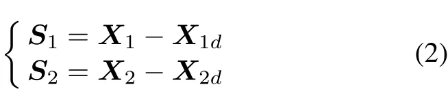
where

Error equations can be obtained from(1)and(2):

Because of unknownS2,G1(X1)S2is defined as an uncertainty,andX2dis designed to be a virtual control lawΩ:

where

The first Lyapunov function is defined as

Next,derivingV1we get

Substituting(3)into(6),we obtain

Substituting(4)into(7)and simplifying it,we get

By referring to Assumption 1,we obtain

Letλmin(k1)be the minimum eigenvalue of known diagonal matrixk1.According to Lemma 3,we acquire

Similarly,letλmin(Λ1)andλmin(Γ(S1))be the minimum eigenvalues of known diagonal matricesΛ1andΓ(S1)respectively.According to Lemma 2 and Lemma 3,we acquire

Substituting(9)–(11)into(8),we get

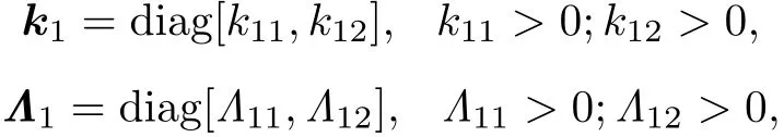
Select the parameters of a virtual controller based on the inverted-U property of the mono basic quadratic function whose peak is a small and positive number,less than or equal to zero,which are described as

or

Because eigenvalues of this diagonal matrixΓ(S1)=diag[tanhtanhare tanhand tanhwe getλ(Γ(S1))=[−1,1]easily.Hence,(13)is simplified to


Relation betweenlandφis shown in Fig.2.

Fig.2 A mono basic quadratic function
In Fig.2,theφ-coordinate value of pointMis

and thel-coordinate value of pointNis

There are some characteristics analyzed as follows.

It shows that ifS2is bounded,S1is finally stable and bounded under the influence of a virtual control law,that is,

This virtual control law has no effects on convergence ofS2.Therefore,it is substantial to design an actual control law to ensure convergence ofS2.
3.2 Design of an actual control law of SMC
To simplify the design of an actual control law,assumptions and lemmas are given as follows.
Assumption 2ρ2is true in this dynamic model.ρ2is an unknown,bounded and positive number.
From(1)and(2),error equations can be obtained:

Design this actual control law:
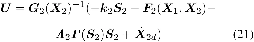
where

Γ(S2)=diag[tanh(μ−12S21),tanh(μ−12S22)],μ2>1.
The second Lyapunov function is defined as

Next,derivingV2we get

Substituting(20)into(23),we obtain

Substituting(21)into(24)and using a familiar procedure of the first Lyapunov function in Section 2.1,it is simplified as


In(25),relation betweenS2and˙V2is described with a mono basic quadratic inequation.Similarly,it is known thatτ2(τ2is a bounded and positive number)can be true by designing suitable parametersk2,Λ2,μ2of that actual controller.
Select the parameters of an actual controller using the similar method as that in Section 3.1.Next,applying them to obtain˙V2τ2,we aquire


Hence,under effects on this actual control law,tracking errorS2can converge to its small neighborhood,and it is

3.3 Design of AS
To compensate for errors caused by input constraints,we design this following AS:

where

σ>0,kn=diag[kn1,kn2],kn1>0,kn2>0,be>0,λmin(kn)is the minimum eigenvalue of diagonal matrixkn.U0is the limited value of the rudder angle.
The input variable of AS is Δurelated to sat(U),andEis the state variable and output variable of AS.Its functions can be divided into two cases as follows:
(i)IfE<σ,there is no control saturation,and the SMC controller works in a linear control zone,meanwhile,AS does not work at all.
(ii)IfEσ,there is control saturation, and the SMC controller turns out to be in a nonlinear control zone. At the same time, input variable Δu=U−sat(U)of AS is not zero,and AS starts working, forcing control errors to decay in a short time.
In case(ii)above,the third Lyapunov function is designed as

Next,derivingV3we obtain

Substituting(30)into(32),we get


IfEσ,there is

In(34),the following two inequations are true:
(i)Ifbe>0,−[2(X2)Δu+beΔu2]0 is always true.
(ii)Ifλmin(kn)>0,−λmin(kn)E20 is always true.
Hence,under this condition ofEσ,there is0,which indicates gradual-approach convergence of AS.
4.Simulation results and analysis
4.1 Simulation conditions
In this section,to demonstrate the performance and feasibility of the proposed SMC and AS,from flight trajectory of a rolling-missile,we select dynamic coefficients on a certain feature point shown in Table 2,where a rollingmissile flies at a speed of 290 m/s and at an altitude of 5 357 m.

Table 2 Dynamic coefficients of a certain feature point
Our simulation goals in this section are as follows:
(i)In order to verify the anti-interference ability of the proposed SMC law,there are 30%parameter perturbation in this simulation environment.
(ii)To testify the effectiveness of the proposed AS controller,comparative simulation examples are the proposed SMC and the proposed AS combined with SMC.
Hence,the following simulation schemes are needed:Scheme(i):SMC;
Scheme(ii):SMC+30%parameter perturbation;Scheme(iii):SMC+AS.
Control parameters are listed as follows:
(i)SMC parameters are as follows:

(ii)AS parameters are as follows:

4.2 Simulation results
To verify the control performance,step-function signals are used here.We set the desired overload to 1g,and the desired angular rate to zero.The rudder angle is limited within –15◦to+15◦.Simulation results are shown as follows.

Fig.3 SMC surface for longitudinal overload
Fig.3 is the SMC surfaceS11for longitudinal overload.
Fig.4 is the SMC surfaceS12for lateral overload.Fig.5 is the SMC surfaceS21of the pitch angular rate.Fig.6 is the SMC surfaceS22for the yaw rate.Fig.7shows the rudder angle of the rolling-missile.Fig.8 shows elevator angle of the rolling-missile.Fig.9 illustrates the pitch angular rate of the rolling-missile.Fig.10 illustrates the yaw rate of rolling-missile.Fig.11 is the step response of longitudinal overload. Fig. 12 is the step response of lateral overload.Fig.13 shows input variables of AS,and Fig.14 shows output variables of AS.

Fig.4 SMC surface for lateral overload

Fig.5 SMC surface for pitch angular rate

Fig.6 SMC surface for yaw rate

Fig.7 Rudder angle of rolling-missile

Fig.8 Elevator angle of rolling-missile

Fig.9 Pitch angular rate of rolling-missile

Fig.10 Yaw rate of rolling-missile

Fig.11 Longitudinal overload of rolling-missile

Fig.12 Lateral overload of rolling-missile

Fig.13 Input variables of AS(SMC+AS)

Fig.14 Output variables of AS(SMC+AS)
4.3 Simulation analysis
4.3.1 Performance of SMC scheme
From simulation results of control scheme(i)and control scheme(ii)showed in Fig.9 to Fig.12,we get tracking errors of SMC under 30%parameter perturbation shown in Table 3.

Table 3 Tracking errors of SMC under 30%parameter perturbation %
As is shown in Table 3,tracking errors of this proposed SMC scheme under 30%parameter perturbation are very small,which verifies its strong anti-interference ability.
4.3.2 Performance of AS scheme
From simulation results of these control scheme(i)and scheme(iii),performance of the AS scheme is summarized as follows:
Firstly,definie the sliding-mode surface based on(2),which represents errors of state variables and their desired values.As shown in Fig.3 to Fig.6,it can be seen that AS plays an important role in reducing errors of the overload and the angular rate.
Secondly,as shown in Fig.7,the AS controller makes the rudder angle change slower.Additionally,it reduces amplitudes of the elevator angle shown in Fig.8.
In addition,as shown in Fig.9,AS leads to smaller amplitudes of the pitch angular rate,convergence in a shorter time,and decrease of fluctuation.Furthermore,it makes amplitudes of the yaw rate reduce shown in Fig.10.
Moreover,as shown in Fig.11 and Fig.12,we obtain its static and dynamic performance indexes of longitudinal overload and lateral overload respectively in Table 4 Table 5.
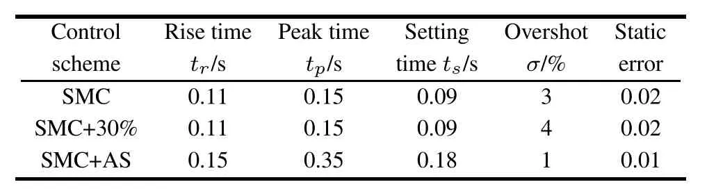
Table 4 Static and dynamic performance indexes of longitudinal overload

Table 5 Static and dynamic performance indexes of lateral overload
Compared with these proposed control schemes above,it is illustrated that control scheme(iii)has some superiority,and they are small overshot and static error.
4.3.3 Performance summary
Firstly,in terms of rapidity,the proposed control schemes(i),(ii)and(iii)make dynamic system reach convergence in a single second.
Then,summarize their stability.On the one hand,it is proved based on the Lyapunov theory.On the other hand,simulation tests show that tested curves are smooth.
Moreover,in terms of their robustness,simulation test of control scheme(ii)illustrates that the proposed SMC scheme has some priority in anti-interference quality.
Finally,analyzing their anti-saturation performance,we can see that the AS scheme plays an essential role in compensating for saturation from simulation test of control scheme(iii).
5.Conclusions
In this paper, a promising solution for a rolling-missile subject to uncertainties and input constraints is provided. The key idea behind this solution is to incorporate the AS technique into SMC to compensate for the nonlinear terms arising from input constraints.
Moreover,based on the Lyapunov theory,it is proved that the designed controller can guarantee dynamic stability.Furthermore,the SMC law with the tanh-type switching function can reduce intrinsic vibration.Simulation results demonstrate the effectiveness of this proposed control scheme.
杂志排行

Journal of Systems Engineering and Electronics的其它文章
- Multi-target tracking algorithm based on PHD filte against multi-range-false-target jamming
- Design,analysis and optimization of random access inter-satellite ranging system
- Parity recognition of blade number and manoeuvre intention classificatio algorithm of rotor target based on micro-Doppler features using CNN
- Uplink NOMA signal transmission with convolutional neural networks approach
- A transceiver frequency conversion module based on 3D micropackaging technology
- Renormalization:single-photon processes of two-level system in free space