LPV modeling and controller design for body freedom flutter suppression subject to actuator saturation
2020-10-24WeiTANGYuWANGJiweiGUZhiweiSUN
Wei TANG, Yu WANG, Jiwei GU, Zhiwei SUN
a School of Automation, Northwestern Polytechnical University, Xi’an 710129, China
b School of Automation Science and Electrical Engineering, Beihang University, Beijing 100083, China
c Research Institute of Unmanned Aerial Vehicle, Northwestern Polytechnical University, Xi’an 710072, China
KEYWORDS Anti-windup compensation;Flutter suppression;Linear parameter-varying interpolation;Model order reduction;Saturation
Abstract In recent years, the Active Flutter Suppression (AFS) employing Linear Parameter-Varying(LPV)framework has become a hot spot in the research field.Nevertheless,the flutter suppression technique is facing two severe challenges. On the one hand, due to the fatal risk of flight test near critical airspeed, it is hard to obtain the accurate mathematical model of the aeroelastic system from the testing data. On the other hand, saturation of the actuator may degrade the closed-loop performance,which was often neglected in the past work.To tackle these two problems,a new active controller design procedure is proposed to suppress flutter in this paper. Firstly, with the aid of LPV model order reduction method and State-space Model Interpolation of Local Estimates(SMILE)technique,a set of high-fidelity Linear Time-Invariant(LTI)models which are usually derived from flight tests at different subcritical airspeeds are reduced and interpolated to construct an LPV model of an aeroelastic system. And then, the unstable aeroelastic dynamics beyond critical airspeed are ‘predicted’ by extrapolating the resulting LPV model. Secondly, based on the control-oriented LPV model,an AFS controller in LPV framework which is composed of a nominal LPV controller and an LPV anti-windup compensator is designed to suppress the aeroelastic vibration and overcome the performance degradation caused by actuator saturation.Although the nominal LPV controller may have superior performance in linear simulation in which the saturation effect is ignored,the results of the numerical simulations show that the nominal LPV controller fails to suppress the Body Freedom Flutter(BFF) when encountering the actuator saturation. However, the LPV anti-windup compensator not only enhances the nominal controller’s performance but also helps the nominal controller to stabilize the unstable aeroelastic system when encountering serious actuator saturation.
1. Introduction
Flutter is a dangerous phenomenon due to the interaction of structural, inertial and aerodynamic loads. Such dynamic instability of the aeroelastic system may lead to a catastrophic structural failure within a sufficiently short stretch time.1Recently, with the wide use of lightweight and flexible materials and structures in modern aircraft design, aeroelastic problems are becoming increasingly urgent.To guarantee the flight safety, one most important thing is to prevent the flutter from happening within the whole flight envelope and actively suppress it if possible.
The passive method such as structural stiffening is traditionally used to reduce the risk of flutter. However, it inevitably introduces an extra weight to the aircraft and degrades the flight performance.The Active Flutter Suppression2(AFS)has been recognized as an alternative to the passive method. The closed-loop control scheme utilizing AFS technology can effectively damp the vibration via active control surfaces and other actuators. Thus AFS technology has more advantages over passive methods in weight saving and efficiency. Especially,with the great development of wideband actuators and control theory, AFS technology is becoming feasible and promising.
In the past decades,considerable efforts have been devoted to AFS technology by employing different control theories.Mahesh et al.3designed a Linear Quadratic Gaussian (LQG)controller for an airfoil wind tunnel model and verified its effectiveness for flutter suppression. Ozbay and Bachmann4implemented H∞control theory successfully to suppress the vibration of a two-dimensional thin airfoil model.An adaptive switching control approach is proposed by Tang et al.5for vibration suppression of flexible structure.Liu et al.6employed a kind of Sliding Mode Control (SMC) scheme to design an active controller, and several numerical results indicated that the given SMC methodology is effective to suppress the vibration of a two-degree-of-freedom viscoelastic airfoil model.Tang et al.7investigated the possibility of designing an adaptive controller based on neural-networks to actively suppress the airfoil flutter. Recently, due to the advantages of Linear Parameter-Varying (LPV) methodology, such as synthesizing automatically scheduled multivariable controller and incorporating rate bounds of the varying parameters to reduce the conservatism,AFS technology employing the LPV framework has received a lot of attention. Barker,8Prime,9and Seiler10et al. applied the LPV methodology to suppress the flutter encountering in different aircraft.
However,the above studies3-10almost designed and verified the active controller based on an inaccurate mathematical model and they mainly focused on the closed-loop system with the precondition that the actuators work normally.On the one hand,because of the fatal risk of flight test at critical and supercritical flutter airspeed,models under these flight conditions are usually built by mathematical methods,such as Computational Fluid Dynamics(CFD)and Computational Structural Dynamics(CSD).11But it is difficult to guarantee the accuracy of the model without flight test validation. Additionally, the models derived from testing data generally have high order, and thus they are hard to be directly utilized in controller synthesis. On the other hand,poles associated with fast modes,such as pitch rate,will lead to high gains for the feedback matrix and consequently high control effort.12As a result,the controller output is easy to exceed the actuator’s physical limits at the occurrence of flutter. If the actuator saturation is not disposed of effectively, the control performance would be deteriorated or even the system instability may happen. Although the anti-windup compensation13has been investigated for conventional flight control,it has not(to the authors’knowledge)previously been applied to the flutter suppression studied here.In order to tackle these challenges,it is necessary to investigate a new active controller design procedure.
Taking into account the strong nonlinearity of the aeroelastic system and the demand for the controller’s adaptability,the LPV framework is more suitable in the overall design procedure. Moreover, Body Freedom Flutter (BFF) which results from the coupling of the rigid body and short-period mode with wing bending14has received extensive attention in AFS technique exploration. Both the X-56 Multi-Utility Technology Testbed (MUTT) aircraft developed by NASA15and the mini MUTT developed by University of Minnesota16,17are well-known platforms to study the active BFF suppression.In this article, a complete synthesis framework comprising the control-oriented LPV modeling and the LPV controller design is proposed. Especially, an LPV controller with antiwindup compensator is designed to suppress the BFF of X-56 MUTT aircraft.
To overcome the shortcomings of the conventional AFS system design method, a new active controller design procedure is proposed for suppressing flutter. Compared with the existing literature, the main contributions of this work lie in the following:
(1) To address the challenge of modeling under critical condition,a practical LPV modeling framework is proposed based on a set of stable reduced-order models derived under subcritical conditions. The extrapolation of LPV model will help us to accurately ‘predict’ the unstable dynamics under dangerous critical condition. The new framework easily incorporates flight testing data under subcritical conditions for model validation and avoids the dangerous test under critical condition.
(2) Distinct from normal active flutter suppression, the actuator saturation that occurs frequently in practice is taken into account, and an anti-windup compensator in LPV framework is presented herein to address such problem. It not only augments the stability of the LPV controller, but also alleviates the control performance degradation in the presence of saturation.
This paper is organized as follows: Section 2 describes the physical and mathematical model of NASA’s X-56 MUTT aircraft and gives the objective of this study.Section 3 presents a
brief interpretation of the LPV framework. Section 4.1 introduces the LPV anti-windup compensator design method. In Section 4.2,anti-windup compensator synthesis for active flutter suppression is given. The numerical simulations are illustrated and discussed in Section 5. Section 6 draws some conclusions.
2. Problem description
2.1. Description of X-56 MUTT
The X-56 MUTT is designed by Lockheed Martin as a versatile,modular,remotely piloted experimental research platform.A brief overview of the system is described below and readers can refer to Ref.15for details. This flight vehicle is a tailless,flying-wing aircraft, and its wings with a high aspect ratio are swept back. This configuration is prone to BFF like other examples of flexible flying wings.There are ten control surfaces in total, including two body flaps (BFL and BFR) and four pairs of wing flaps (left wing flaps: WF1L-WF4L, right wing flaps: WF1R-~WF4R). They can be employed in different combinations to generate aerodynamic force for gust load alleviation and flutter suppression.The deflections of these actuators are all limited within [-20°, 20°]. This aircraft is equipped with a number of sensors to measure flight dynamic response.Fig.1 shows the locations of the gyroscope(IMU-MIDG),six accelerometers (ASESNSR 1000 is mounted on the mass center; ASESNSR 400, 600, 1100 and 1300 are mounted in the four different positions on the wingtips) and ten control surfaces of this flight vehicle.18
The X-56 MUTT aircraft’s fundamental mathematical models studied in this paper are a set of high-fidelity statespace representations given in Ref.19,and they describe the different longitudinal dynamics under 12 flight conditions below the critical airspeed illustrated in Fig. 2, where Ai, Bi, Ci, Di,(i=1, 2, ... , 12) are the corresponding system matrices.
These models are all of two inputs, three outputs, and 48 states, consisting of 16 structural states, 2 rigid body states,and 30 aerodynamic states. The longitudinal dynamics of X-56 MUTT are dominated by the short period and phugoid modes, and by the first few aeroelastic modes. The elements of state x, input u and output y are presented as follows:

where η1×8is the modal displacement, ˙η1×8is the derivative of the model displacement with respect to time, α is the angle of attack, rad; q is the pitch rate, rad/s; w1×30is the unsteady aerodynamic state, δ3is the deflection of WFL3 and WFR3,rad; δ4is the deflection of WFL3 and WFR3, rad; acis the acceleration at center of gravity, m/s2; and awaveraged wing-tip acceleration, m/s2.
2.2. Objectives of this study
Distinct from conventional flight control,two significant challenges are faced in the flutter suppression controller design:
(1) Owing to the high risk of flight test at critical and subcritical flutter airspeed, models under these flight conditions are hardly obtained from flight data.20Although these models can be mathematically derived by integrating CFD and CSD under all flight conditions, it is hard to guarantee the accuracy of the model without flight test verification. Thus, it is necessary to develop a reliable control-oriented modeling method for flutter suppression based on the verified models at subcritical flutter speed.

Fig. 1 Schematic of X-56 MUTT.18

Fig. 2 Twelve state-space LTI models of X-56 MUTT.

Fig.3 Control surfaces’physical characteristics of X-56 MUTT.

Fig. 4 Procedure of flutter suppression considering saturation nonlinearity.
(2) Due to the physical limitations of actuators, the saturation may happen when a considerable aerodynamic force is needed. The high performance over the entire flight range is hardly ensured once the saturation occurs.Consequently, an efficient anti-windup method is urgently required.The control surfaces’physical characteristics of X-56 MUTT are pictorially depicted in Fig. 3, where uiis the desired deflection imported from the controller,σ(ui)is the actual deflection of the control surface, and k1is the slope.
To tackle the above challenges, a new controller synthesis procedure is developed for flutter suppression considering saturation nonlinearity,which is illustrated in Fig.4.The process consists of two steps:control-oriented LPV modeling and control scheme design. In the first step, the control-oriented LPV models are obtained from a set of LTI models by employing the SMILE technique and parameter-varying oblique projection.19In the second step, a series of LPV control theories are implemented to design anti-windup controllers for the aeroelastic plant involving input magnitude constraints,which can alleviate the performance degradation and stabilize the system when encountering saturation.
3. Control-oriented LPV modeling
3.1. LPV model
Linear Parameter-Varying (LPV) framework is introduced by Shamma and Athans,21to overcome the drawbacks of classical gain-scheduling methods that lack stability and performance guarantee for rapid changes of the scheduling variables.A continuous LPV system described in state-space representation is of the form

where x( t)∈Rnxis the state vector,u(t )∈Rnuis the input vector,y(t )∈Rnyis the output vector,and ρ(t )∈Rnρis a measurable parameter vector, called as scheduling parameters.
Motivated by the strong nonlinearity of aircraft dynamics,the LPV paradigm is a prevalent design approach in flight control,where the scheduling parameters are usually airspeed,altitude, or other relevant parameters for different control objectives.The grid-based LPV model is more common to represent the parameter dependence, and it patches together an indexed collection of linear systems to model the nonlinearity.The grid-based representation is described as

where G defines a set of LTI models on the n grids. Consequently, the LPV model G(ρ(t)) is evaluated by n LTI models Giwith state-space data Ai, Bi, Ci, Dion the corresponding operating point ρi, approximating the infinite dimension of the parameter domain by a finite, gridded domain.
The aforementioned high-fidelity LTI models of X-56 MUTT are arranged by airspeed value Vaand construct a grid-based LPV model by setting the grid as {30.6:3.4:68} m/s. The airspeed root loci across in the flight envelop of the resulting 48th order grid-based LPV model are shown in Fig.5(a). Obviously, with the increase of airspeed, one of these modes(the 1st aeroelastic mode)is approaching the imaginary axis of s plane.From the zoomed part of this figure,it is obvious that Va=68 m/s is very close to the flutter critical speed.If the airspeed rises further, the aeroelastic mode will inevitably lead to divergent vibration. As introduced in Ref.14,because of the coupling of short-period mode and the 1st aeroelastic mode, a fatal vibration is provoked and this kind of vibration is called body freedom flutter.
Fig. 6 depicts the frequency responses from WF3 (δ3) to q and acat Va=68 m/s, and the first five modes are seen in the figure.The frequency of the 1st aeroelastic mode is approximately 18 rad/s (2.8 Hz) under this flight condition.
To clearly illustrate the variation of the first five aeroelastic modes and the short-period mode with airspeed, the velocity/frequency/damping plots are shown in Fig. 7. As the airspeed increases, the frequencies of short-period mode and the 1st aeroelastic mode are approaching closely to each other. As the airspeed reaches 68 m/s,the damping ratio of the 1st aeroelastic mode tends to zero. In other words, the system is nearly unstable, which means body freedom flutter occurrence in a flying-wing drone.
3.2. LPV model order reduction
The computational complexity to synthesize the AFS controller strongly depends on the order of the aeroelastic model,and thus a low-order model is beneficial to design a low-order controller. The model order reduction techniques have been intensively investigated to reduce the high-order aeroelastic model into a reduced-order state-space model while retaining the dominant behavior of the system. The efforts in this field include balanced realization and truncation,22Krylov-based projection,23the hybrid SVD-Krylov approach,24and the Proper Orthogonal Decomposition25(POD) based fluid ROM. By these methods, a satisfying low-order LTI aeroelastic model can be obtained from the high-order aeroelastic model. But if several control-oriented models are wanted, the coherence of the states cannot be guaranteed. Recently, a new order reduction in the LPV framework using parametervarying oblique projection19is proposed to avoid the parameter rate dependence and maintain a consistent state-space basis for the reduced-order system. This novel method is adopted herein for model order reduction.
Generally,the ideal control-oriented LPV controlled model is below the 20th order. By numerical experiments, the reduced-order model of 12 states meets our requirements.The resulting model only consists of twelve states(α,q,η1×4, ˙η1×4), which can be interpreted as a short-period approximation that includes the first aeroelastic mode.The airspeed root loci across Va∈[30.6, 68] m/s of the resulting 12th order grid-based LPV model are shown in Fig. 5(b). Obviously, the loci of the dominant aeroelastic modes and the short-period mode are reserved in the 12th order LPV model and almost coincide with those of the original high-fidelity LPV model, which is important for the BFF analysis and its controller design.
3.3. Interpolation of LTI models
Since the flight flutter test is dangerous, the model describing the aeroelastic system at critical airspeed is hard to obtain.Besides,the LPV model reduction for the unstable LPV system is still a challenging problem. Therefore, a set of stable LTI state-space models derived at subcritical speeds are utilized in our work to estimate the LPV model and‘predict’the unstable states beyond the critical airspeed.Based on the stable LTI models with the 12th order, the LPV model is estimated by using SMILE technique.26Since the local LTI models are not guaranteed to represent in a coherent state-space form,all local LTI models should be transformed into a coherent state-space representation firstly.
After the coherent local LTI models Hl(l=1,2,···,m) are obtained,they can be interpolated to set up the estimated LPV model(Va) for the parameter-dependent aeroelastic system.The type and size of the resulting optimization problem heavily depend on the choices of the parameterization of(Va) and the corresponding cost function.Herein,we employ a quadratic matrix polynomial function of airspeed to represent the LPV model27

Fig. 5 Airspeed root loci of 48th and 12th order LPV models across Va ∈30.6,68[ ] m/s.

Fig. 6 Frequency responses at Va=68 m/s.

Fig. 7 Velocity/frequency/damping plot of the 48th order LPV model.

Fig. 8 Modeling relative error between interpolated LPV model and original LTI model with 48 states.
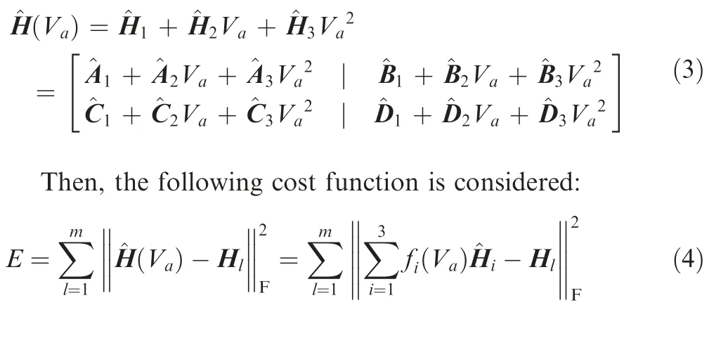


Fig. 9 Airspeed root loci of 48th and 12th order LPV models across Va ∈60,78[ ] m/s.


Fig. 10 LPV anti-windup control block diagram.
Fig.8 depicts the modeling relative error between the interpolated LPV model and the original LTI model of 48 states under different flight conditions. The maximal relative error is approximately 1.56% when Va=68 m/s. Therefore, the interpolated LPV model meets the requirements to estimate the expanding flight envelope.
3.4. Unstable aeroelastic dynamics
For easier observation of the unstable aeroelastic dynamics,the LPV model is extrapolated to cover the unstable region,ranging from 60 to 78 m/s. Fig. 9 compares the airspeed root loci of the interpolated 48th order LPV model and the interpolated 12th order LPV model. Obviously, with the increase of airspeed, the short-period mode moves further away from the imaginary axis,and the 1st aeroelastic mode goes gradually across the imaginary axis.The crossover point of the 1st aeroelastic mode corresponds to critical flutter condition,where the airspeed is approximately 69.4 m/s and the flutter frequency is about 2.82 Hz (17.72 rad/s).
It is worth noting that the LPV interpolation technique only guarantees the accuracy of the estimated model within a small extension of the current parameter domain. In order to ensure the reliability of the model over a larger range,in practice, an AFS controller can be designed to secure the stability of the aircraft in the extended domain utilizing the predicted model. Then, a safe flight test with the active controller can be carried out to acquire the data to validate and correct the mathematical model.

Fig. 11 Saturation nonlinearity restricted in conic sector.
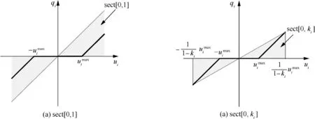
Fig. 12 Dead-zone representation of saturation nonlinearity.

Fig. 13 Equivalent transformation of a saturation control diagram.
4. Control scheme
4.1. Anti-windup synthesis for LPV systems with actuator saturation
The anti-windup technique is an auxiliary compensation method to tackle the actuator saturation, which is widely encountered in practice. Desired anti-windup design requirements include ‘‘stability of the closed-loop system, recovery of the linear design specifications in the absence of saturation and smooth degradation of the linear performance in the presence of saturation”.28There are two general approaches in anti-windup design. The popular one is anti-windup compensation that employs the following ‘two-step’ procedure.29Firstly,a nominal controller is synthesized ignoring the saturation nonlinearity, and it applies standard linear control theories. Secondly, a so-called anti-windup compensator is designed and added to address the saturation. This method not only ensures stability and less performance degradation when saturation occurs but also reduces the difficulty of the anti-windup controller design procedure. In this section, the anti-windup controller design method is presented in the‘two-step’ procedure.
Based on the aforementioned LPV model, an LPV controller with anti-windup compensation is specially designed for body freedom flutter suppression. Timely and accurate control action is always necessary for flutter suppression. But actuator saturation, namely the deflection limits, dramatically restricts the achievable performance and even causes instability. If the controller does not take these limits into account appropriately, the fatal risk may arise.
To compensate the incorrect control signal in saturation condition, the anti-windup control structure shown in Fig. 10 is explored, where AWρis the anti-windup compensator, p is the discrepancy between u and σ(u), Pρand Kρare the controlled plant and the nominal controller described in linear parameter-varying paradigm, represented as follows:


Fig. 14 Control interconnection for anti-windup flutter suppression.

Table 1 Sector range and performance level.

Fig. 15 Airspeed root loci of closed-loop system across Va ∈60,78[ ] m/s.


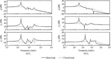
Fig. 16 Frequency responses of open-loop and closed-loop system at Va=69.4 m/s.
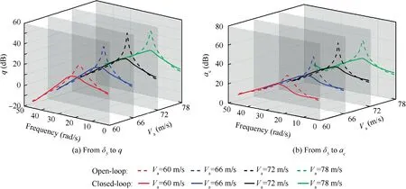
Fig. 17 Open-loop and closed-loop frequency response.
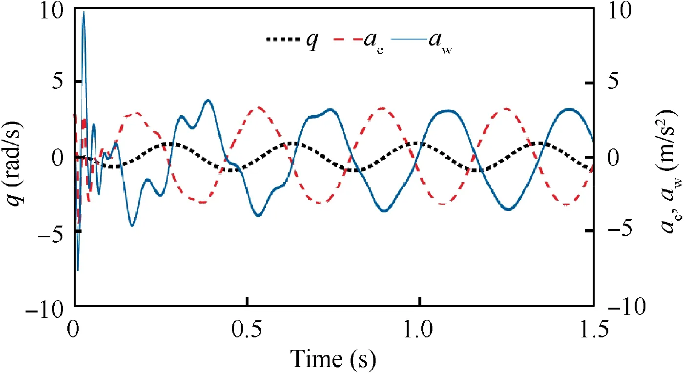
Fig. 18 Open-loop responses at Va =69.4 m/s.
The two-step anti-windup procedure is utilized in this work.Firstly, the nominal LPV controller Kρis designed to stabilize the open-loop system without consideration of the actuator saturation, and different LPV control theories32,33can be employed in this procedure. Secondly, the anti-windup compensator AWρis designed to enhance the performance when the actuators perform in the saturation region, and it is of the form

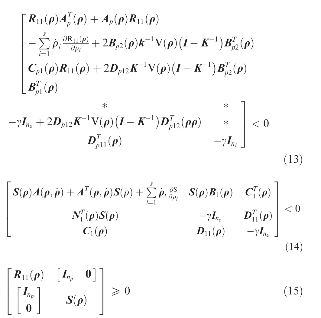
for the whole parameter domain, then there exists an npth order LPV anti-windup compensator AWρto stabilize the closed-loop system exponentially and have the performance||e||2<γ||d||2for the whole parameter domain when the condition |ui|≤(1/(1-ki))uimax, i=1, 2,···,nuholds.
For the efficiency of computation, the synthesis condition for LPV anti-windup compensator (see Eqs. (13)-(15)) can be solved by minimizing a linear objective under the three Linear Matrix Inequality (LMI) constraints therein, which is formulated as

where ε is a self-defined parameter related to the computational accuracy. This is a typical LMI optimization problem,which can be solved by the MATLAB function min(cx). By the authors’experience,there may be no solution when solving the LMIs (see Eqs. (13)-(15)), but this problem can be addressed by selecting an appropriate value of ε.
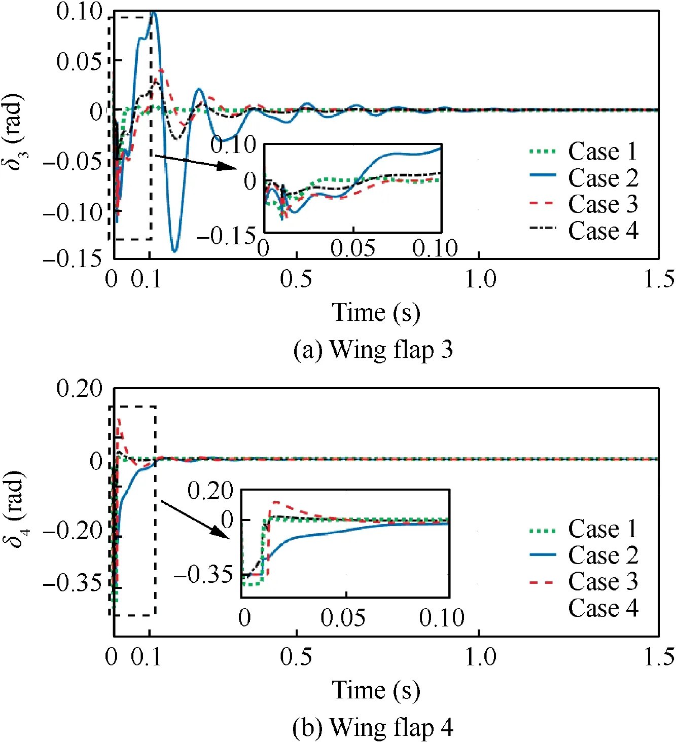
Fig. 19 Deflections of flaps at Va =69.4 m/s.
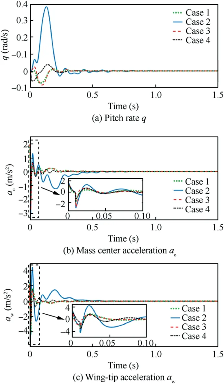
Fig. 20 Closed-loop responses at Va=69.4 m/s.
Given the solution of R11(ρ), which is the (1, 1) element of the positive definite matrix R(ρ), the establishment of R(ρ) is not unique. There is a feasible selection as follows:

4.2. LPV anti-windup controller design for active flutter suppression
In this part, the LPV anti-windup compensation technique presented in Section 4.1 and the 12th order LPV model which is gridded and described at 10 linearly spaced airspeeds covering Va∈[60,78]m/s are employed to synthesize the anti-windup active flutter suppression LPV controller for X-56 MUTT aircraft.
The control interconnection of the anti-windup flutter suppression system is depicted in Fig.14.The performance objectives are specified through the proper selection of the weighting functions Wu, Wd, Weand Wn, which are implemented to the input and output of the generalized open-loop system. The nominal LPV controller K(Va) is designed to minimize the induced L2norm of the closed-loop generalized LPV system and hence seeks to attenuate the structural vibration of the aircraft with a limited control authority. The induced L2norm γ describes the performance level and is defined as

Fig. 21 Open-loop responses at Va =78 m/s.

Fig. 22 Closed-loop performance of Case 4 at Va=78 m/s.

where the weighted output signal eG=[e1, e2]T, and the weighted input signal dG=[d1, d2]T. The performance level γ indicates the largest amplification of input signals over all frequencies and input/output directions. In our application,decreasing this value corresponds to attenuating the aeroelastic mode in response to disturbances. Thus, the goal of antiwindup compensation design is to construct an anti-windup compensator that guarantees a performance level as small as possible.
Firstly, ignoring the actuator saturation, the nominal LPV controller K(Va) is derived by utilizing the induced L2norm control method for bounded parameter variation rates in Ref.32. In a practical way, the rate of parameter (Va) is bounded at the interval [-10, 10] m/s2to further reduce the conservativeness of the designed controller. Furthermore, to solve the LMI optimization problem in the nominal LPV controller synthesis (see Theorem 4.1 in Ref.32), three basis functions are selected as follows:

The actuator weight Wuis employed to limit the controller’s output to a specific frequency range. It aims at reducing undesired interaction with low-frequency rigid-body dynamics and with unmodeled dynamics in high-frequency bands. Since the BFF critical frequency is about 2.82 Hz, Wuis selected as a band-stop filter to directly shape the controller so that it exports control signal in a narrow frequency range around the critical frequency.The primary objective of the performance weight Weis to limit the peak values of responses and to scale each of them. It is done by dividing each output by its maximal expected or allowed value. The disturbance weight Wdreflects input disturbances and the noise weight Wnreflects sensor noise corrupting the measurements. Their magnitudes have impacts on input and output robustness margins, and determine the closed-loop performance in the presence of uncertainties. Besides, to simplify the controller synthesis, the weights do not change with the scheduling parameter Va.
Then,substituting the above designed parameters,the nominal LPV controller K(Va)is synthesized and it is of 3 inputs,2 outputs and 16 states since the second-order actuator weight Wuintroduces four additional states into the controller.Moreover, it is arranged by the airspeed Vaand a grid representation with 10 uniformly spaced points is used to cover the parameter domain [60, 78] m/s. The resulting closed-loop performance level is γnom=5.1831.
Afterwards, the LPV anti-windup compensation technique discussed in Section 4.1 is implemented to design an LPV compensator to tackle the possible saturation problem.To quicken the computation of Eq. (13), the self-defined parameter ε is chosen as 10-8.As mentioned above,the anti-windup compensator design pursues stronger regional stability (a larger k value in the range of[0,1]),but this will degrade the LPV controller performance. To illustrate this point, a series of LPV anti-windup compensators AW(Va) are designed by gradually decreasing k from 1 to 0.99,and the resulting closed-loop performance level γ is shown in Table 1. Obviously, the performance level γ degrades with the growth of sector-bound constraint k,although a larger k corresponds to a bigger regional stable region. Trading off between sector range and the achieved performance level γ, we select k=0.999 by trial and error.
5. Numerical simulation and results
5.1. Linear numerical simulation
Ignoring the actuator nonlinearity, the closed-loop LPV system is constructed by interconnecting P(Va)and K(Va)ranging from 60 to 78 m/s. The effect of the flutter suppression controller on airspeed root loci is shown in Fig.15.In comparison with Fig. 8(a), the locus of the 1st aeroelastic mode is altered by the controller to stay within the left half-plane with a drastic improvement in damping, the lowered short-period frequency and a slight increase in damping. It means that the closedloop system remains stable when Vareaches 78 m/s , so the enhanced critical airspeed should be beyond 78 m/s.
The open-loop and closed-loop frequency responses at Va=69.4 m/s are compared in Fig. 16. It is obvious that the nominal LPV controller effectively damps the 1st aeroelastic mode, but other frequency ranges remain nearly unaffected due to the narrow-band property of the controller.
Fig. 17 shows the frequency responses under other four fixed operating conditions(Va=60,66,72,78 m/s)and it further verifies that the nominal LPV controller K(Va) can effectively suppress the aeroelastic vibration without the limit of saturation.
5.2. Nonlinear numerical simulation in time domain
In the nonlinear numerical simulation,the actual deflections of the control surfaces are limited to[-0.35,+0.35]rad,which is approximately [-20°, +20°]. A short-time pulse, with a duration of 0.1 s and amplitude of 0.35 rad,is imposed on wing flap 4 as a disturbance to motivate the flutter.Meanwhile,in order to demonstrate the necessity of using the parameterized control law, we design a constant (robust) controller at the airspeed Va=69.4 m/s by applying H∞synthesis. For a fair comparison, the same weighting functions used in parameterized controller synthesis are chosen here:

The controllers and the anti-windup compensator are activated immediately once the disturbance is introduced. Owing to the nonlinearity, the controller performance is evaluated by time-domain simulations, instead of frequency-domain frequency response comparison.
Two typical operating conditions are considered,Va=69.4 m/s and Va=78 m/s. This first one represents nominal LPV controller without the limit of actuator saturation.

Fig. 23 Deflections of wing flaps at Va=78 m/s.
the critical flutter airspeed and the second one is the upper boundary of the flight envelope.For easy understanding of the important role of anti-windup compensation, four controllers in different cases are discussed and compared with simulations,which are listed as follows:
Case 1. Nominal LPV controller without the limit of actuator saturation.
Case 2. Saturated nominal LPV controller without antiwindup compensation.
Case 3. Saturated nominal LPV controller with anti-windup compensation.
Case 4. Nominal controller designed at 69.4 m/s without the limit of actuator saturation.
It should be pointed out that LPV controller in Case 1 and H∞controller in Case 4 are both ideal cases without consideration of actuator limits. They are used as a benchmark for closed-loop performance comparison.
(1) Critical flutter airspeed (Va=69.4 m/s)
At critical airspeed,the flutter is induced by the disturbance and the open-loop aeroelastic responses are persistent oscillations, which are shown in Fig. 18.
To suppress the flutter, the two controllers are designed to stabilize the open-loop system. Fig. 19 plots the actual deflections of flaps (σ (u) in Fig. 14) in four cases. As shown in Fig. 19 (b), a slight saturation of wing flap 4 happens around the initial time in Case 2 and Case 3.After that,the deflections tend to zero.This implies that the controller works in a nonlinear state during very short time.
The closed-loop responses of the four cases are compared in Fig. 20. It is clear that the nominal LPV controller (Case 1)shows great efficiency in flutter suppression.However,the performance of the same LPV controller is seriously degraded in Case 2 when taking into account the saturation limits.In comparison with Case 1,large fluctuation can be easily observed in Case 2, although the flutter is suppressed successfully. On the contrary, the LPV controller with anti-windup compensation brings a smooth response with little fluctuation, and achieves comparable performance as Case 1. These results show that the anti-windup compensation is able to greatly alleviate the performance degradation when encountering slight saturation.On the other side, in contrast to the nominal LPV controller,the H∞controller in Case 4 exhibits superior performance at critical speed, and no saturation happen during the stabilization.
(2) Supercritical airspeed (Va=78 m/s)
This velocity is beyond the critical flutter airspeed.Theoretically, the aeroelastic system under this condition is seriously unstable. Thus, as shown in Fig. 21, the open-loop responses are divergent.
The constant controller(Case 4)designed at critical speed is reused here to suppress the flutter and the closed-loop performance is illustrated in Fig. 22. Obviously, the divergent responses imply that the H∞controller fails to stabilize the aeroelastic system. Hence, only the first three cases are compared in the next discussion.
Similar to the first simulation,the actual deflections of flaps 3 and 4 in Cases 1-3 are illustrated in Fig.23.It is obvious that the flaps in Case 2 encounter serious saturation over the whole time duration.On the other side,the flaps in Case 3 only reach the actuator limits at the initial short time. After that, the deflections of flaps in Case 3 go down quickly. Hence we can say that the nominal LPV controller completely loses its efficiency and traps into deep saturation. On the other side, the anti-windup compensator helps the nominal controller get away from the deep saturation. It is clear that the controller in Case 3 works in linear state most of the time.

Fig. 24 Closed-loop responses at Va=78 m/s.
The rigid-body and aeroelastic responses of the drone at supercritical airspeed are depicted in Fig. 24 for performance comparison. It easily observed that the nominal controller in Case 1 quickly stabilizes the system since the magnitude limits of actuators are not taken into account in this simulation. By comparing with Fig. 22, it can be concluded that the constant controller cannot continuously suppress the flutter of the timevarying aeroelastic system. For this reason, a parameterized control law is preferred in the application of the AFS system.
Moreover,the nominal controller loses its efficiency in Case 2, in which the nonlinear saturation is considered. The special nonlinear flutter featured by the Limit Cycle Oscillation(LCO)35is generated. Distinct from the typical divergent response,the nonlinear flutter is attributed to the actuator saturation.We should note that large periodical oscillation is still very harmful to the aircraft structure. The closed-loop system under the supercritical condition requires a larger force to stabilize the aeroelastic mode in comparison with critical condition. So the deeper saturation and the worse performance can be observed in Case 2. In contrast to the nominal controller, the LPV controller with anti-windup compensation in Case 3 perfectly stabilizes the closed-loop system, and greatly alleviates the deteriorated performance due to saturation.Fig. 24 clearly illustrates that it produces quickly decayed responses comparable to Case 1. Since Va=78 m/s is the worst condition of the entire flight envelope, it is concluded that the proposed anti-windup LPV controller is capable of effectively suppressing the body freedom flutter and providing a satisfying performance in the entire flight envelope.
6. Conclusions
In this article,a new anti-windup LPV controller design procedure is proposed for active flutter suppression. The proposed procedure consists of the control-oriented LPV modeling and the anti-windup LPV controller synthesis.It addresses the difficulty to obtain a reliable mathematical description of the rigid-body and aeroelastic dynamics under (or slightly over)critical condition by extrapolating the LPV model. Moreover,the numerical simulations demonstrate that the anti-windup LPV controller, which is designed by the proposed procedure,not only greatly alleviates the performance degradation due to actuator saturation, but also efficiently improves the stability of the aeroservoelastic system in saturation.In the near future,the proposed approach to design an AFS system in LPV framework will be further developed, for instance, the antiwindup compensation for actuator’s rate saturation will be considered.Moreover,the wind tunnel experiment will be carried out to validate the performance of the proposed approach.
Acknowledgements
The authors are grateful to Ms. Ziqing MA for polishing the sentences.This study was co-supported by the National Natural Science Foundation of China (No. 61573289), Space Science and Technology Fund, and Natural Science Basic Research Plan in Shaanxi Province of China (No. 2019JM-042), and Fundamental Research Funds for the Central Universities of China (No. 3102019ZDHKY11).
杂志排行
CHINESE JOURNAL OF AERONAUTICS的其它文章
- A novel surrogate modeling strategy of the mechanical properties of 3D braided composites
- A user-friendly yield criterion for metals exhibiting tension-compression asymmetry
- Aerodynamic characteristics of morphing wing with flexible leading-edge
- High cycle fatigue failure with radial cracks in gears of aero-engines
- Motion equations of hemispherical resonator and analysis of frequency split caused by slight mass non-uniformity
- Light weight optimization of stratospheric airship envelope based on reliability analysis
