CFD simulation of helicopter rotor flow based on unsteady actuator disk model
2020-09-25BARAKOSFITZGIBBONKUSYUMOVKUSYUMOVMIKHAILOV
G.N. BARAKOS, T. FITZGIBBON, A.N. KUSYUMOV,S.A. KUSYUMOV, S.A. MIKHAILOV
a James Watt School of Engineering, Glasgow University, Glasgow G12 8QQ, United Kingdom
b Department of Aerohydrodynamics, Kazan National Research Technical University named after A.N.Tupolev,Kazan 420111, Russia
KEYWORDS CFD;Fully resolved blades rotor;PSP rotor;Surface circulation distribution;Unsteady actuator disk model
Abstract Actuator Disks (AD) can provide characterizations of rotor wakes while reducing computational expense associated with modeling the fully resolved blades. This work presents an unsteady actuator disk method based on surface circulation distribution combined with empirical data, blade element theory and rotor momentum theory. The nonuniform circulation distribution accounts for 3D blade load effects, and in particular, tip loses. Numerical simulations were conducted for the isolated pressure sensitive paint model rotor blade in hover and forward flight using the HMB3 CFD solver of Glasgow University.Validation of CFD results in comparison with published numerical data was performed in hover,for a range of blade pitch angles using fully turbulent flow and the k-ω SST model. In forward flight, the vortex structures predicted using the unsteady actuator disk model showed configurations similar to the ones obtained using fully resolved rotor blades. Despite the reduced grid cells number, the CFD results for AD models captured well the main vortical structures around the rotor disk in comparison to the fully resolved cases.
1. Introduction
CFD analyses for rotary wings with fully-resolved rotor blades are still expensive and may not be necessary for certain studies,like investigations of far-wakes of rotors, or rotor wake interactions and wake encounters.In Ref.1,it is noted,that despite of significant progress CFD methods for fully resolved blades simulation in wind turbine aerodynamics simple, inexpensive methods are still actual in design and aeroelasticity applications. For example, Blade Element Momentum (BEM) theory methods provide comprehensive tool for wind turbines, but only under the simplest conditions: constant wind speed with zero yaw error.2
More advanced approach occupying a fidelity space between CFD methods for fully resolved blades simulation and comprehensive methods are source-based methods,including actuator lines and actuator disks,can provide characterizations of rotor wakes while reducing computational expense associated with modeling the fully resolved blades.
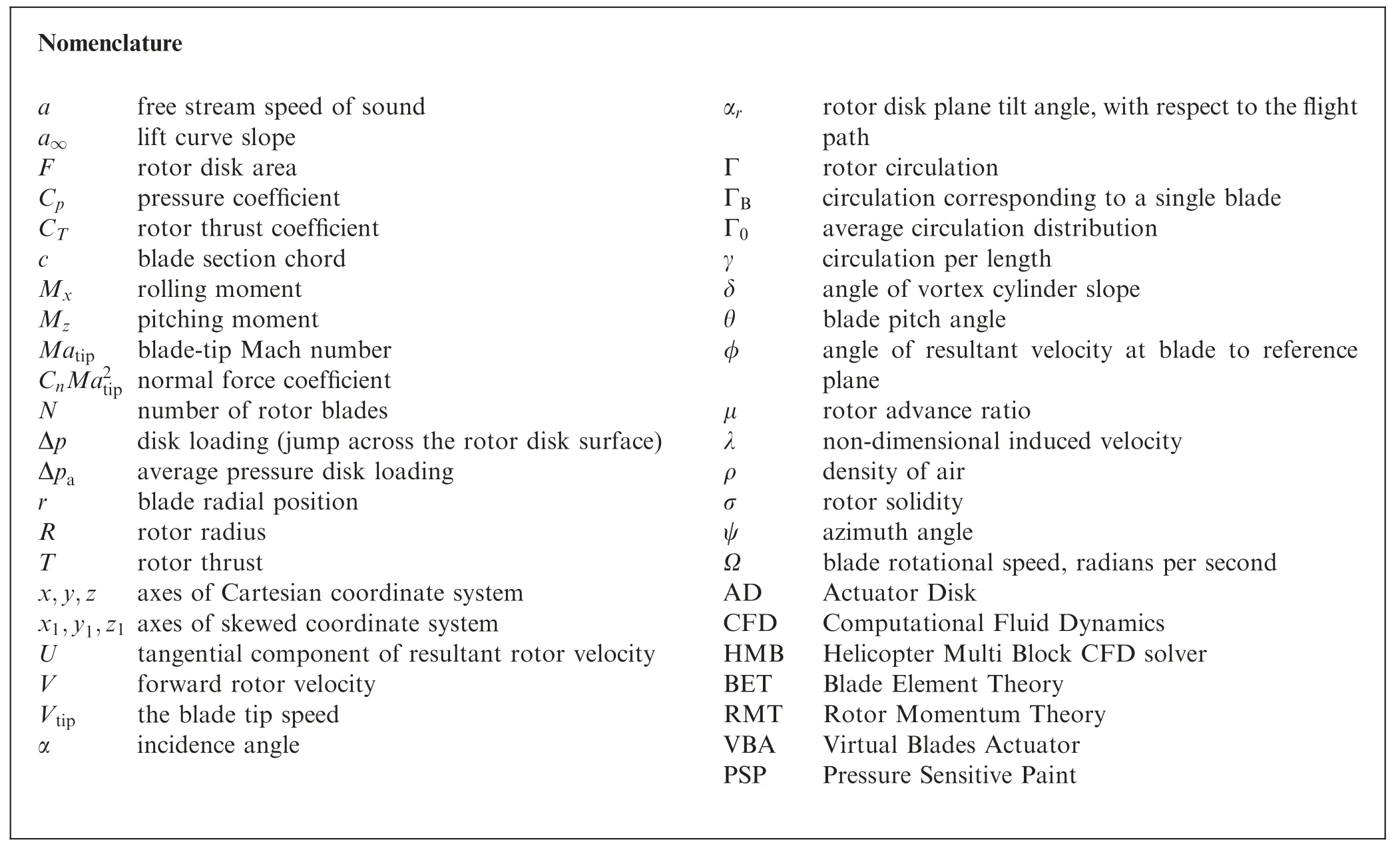
For this reason, actuator models of rotors and propellers have their place in the tool-chain of engineering methods available to helicopter designers. An advantage of the Actuator Disk (AD) models is easy implementation on any computational mesh and low demand for computer recourses.
Actuator-lines method3is a variant of the actuator-blade method whereby the blades are modeled by forces acting along filaments sources lines.These body forces are typically derived from a BEM method using tabulated airfoil data.To avoid discontinuities, each line’s loading is distributed over grid points using a ‘‘regularization function” that spreads a sources influence at a distance away. Churchfield et al.4presents recent advances in the actuator-lines method and improved, higher fidelity, actuator-line implementation.
Classic actuator disk models allow the use of steady-state CFD, significantly reducing the required computer time and memory. The actuator disk approximates the rotor using an infinitely thin source of momentum modeled as a pressure jump across the disk. Between fully resolved blades with detailed CFD grids around them, and blade element momentum models of rotors,actuator disks can reproduce rotor/body interaction or rotor installation effects.
The momentum source is not affected by the presence of other rotors or a fuselage. For this reason, the effect of the rotor disk is simplified and the method,although computationally efficient, can only be used for initial estimates of the fuselage loads5-7or wake interactions with certain parts of the fuselage. The other restriction of this formulation is that is valid only for trimmed conditions and only allows for time averaged estimates of rotor-body interactions.
If needed,an AD can be converted to actuator line method,and can be used to provide some wake structure in the rotor near-field, as well as periodic, instead of averaged forcing on other rotors or on fuselage parts.
In reality, the effect of blades on the fuselage is unsteady.For this reason, the vortical structure of the flow around a fuselage in rotor-body interaction is different than what is predicted by steady-state actuator-disk methods. This problem can be partly solved using unsteady actuator disk models,8popular for flows around propellers. The disk surface is divided in the azimuthal direction,while a time-varied pressure jump and a tangential velocity are specified.2,9The flow parameters are updated with respect to the azimuth angle at each time step to simulate the unsteady flow effect induced by the rotating blades. Unlike actuator line methods, the AD approach does not require averaging of the source data to prevent singularities. The unsteady AD approach was used in Refs. 9,10 for simulation of rotor/fuselage interactions. In Ref. 11 the AD method was established in order to calculate the unsteady aerodynamic characteristics of a tilt-rotor in a conversion mode.
For current time accurate implementation of the AD method is a state of art problem requiring description of forces distribution acting on the disc actuator surface. This requires to determine the intensity of the AD sources intensity and then to add the corresponding body forces to the Navier-Stokes equations. Since no surface is needed in the grid, the position of the sources can be changed without transformation of the initial grid.
In addition, appropriate theory must be used to determine the AD source intensity.In most published references the body forces are typically derived from a BEM method that uses tabulated airfoil data.2,9,12This classic BEM method is based on strip theory and requires corrections particularly near the blade tip region, where tip loss effects are present. In Ref. 2,it is noted that such correction can be applied using Prandtl’s approach.13
This paper adopts a different approach using AD to approximate the wake structure of a rotor in hover or forward flight.The AD implementation is similar to Lynch et al.2and is based on momentum sources.The advantage of this approach is that it does not require significant rearrangement of the CFD girds used for example for isolated fuselage computations.
Most AD methods apply time-varied sources distributed on the disc actuator surface in the form of a pressure jump. The pressure jump can be localized at an‘‘active”part of the actuator disk where the blades are present.The extend of this‘‘active” part corresponds to the planform of a fully resolved blade.In Refs.10,11,such approach was termed unsteady Virtual Blades Actuator (VBA) model.
For structured hexa-grids the implementation of the AD disk models both special types of boundary conditions, and embedding of body force terms in the Navier-Stokes equations can be used. Using local grid refinement for structured hexagrid allows for efficient and accurate identification of the disk area covered by the rotor blades,followed by the addition of a momentum source.2
Although several AD models are available in the literature,some nonuniform models have not been presented in any detail before, and are given here as an alternative to existing AD models.In this paper the pressure jump across the AD induced by the blades is estimated using prescribed circulation distributions. The nonuniform circulation distribution accounts for 3D blade load effects, and in particular, tip loses.
The AD model is used here for simulations of rotor flow wakes employing the Pressure Sensitive Paint (PSP) rotor14and results are compared with computations with fully resolved rotor blades.Results of the vortex structure visualization show the rotor wake configuration similar to the fully resolved rotor blades simulation in forward flight.
2. CFD flow solver and aerodynamic models
All calculations were performed using the parallel CFD solver HMB314(Helicopter Multi Block)solves the dimensionless 3D Navier-Stokes equations in integral form using the Arbitrary Lagrangian Eulerian (ALE) formulation for time-dependent domains with moving boundaries:

where V(t) is the time dependent control volume, ∂V(t) its boundary, W is the vector of the conservative variables[ρ,ρu,ρv,ρw,ρE]T, and Fiand Fvare the inviscid and viscous fluxes.
The viscous stress tensor is approximated in HMB3 using the Boussinesq hypothesis,15complemented by different turbulence models including one equation models of the Spalart-Allmaras family16,17and two-equation models of k-ω family.18-20Algebraic Reynolds stress models are also available.
The Navier-Stokes equations are discretised on the multiblock grid, using a cell-centered finite volume approach. A curvilinear coordinate system is adopted to simplify the formulation of the discretized terms,since body-conforming grids are adopted. The system of equations to be solved is:

where Wi,j,kis the vector of conserved variables in each cell,νi,j,kdenotes its volume and Ri,j,krepresents the flux residual.
The upwind scheme proposed by Osher and Chakravarthy21is used to resolve the convective fluxes for its robustness, accuracy and stability properties. The Monotone Upstream-centered Schemes for Conservation Laws(MUSCL)variable extrapolation method22is employed in conjunction to formally provide second-order accuracy.Van Albada et al.23is also applied to remove any spurious oscillations across shock waves. The integration in time is performed with an implicit dual-time method to achieve fast convergence. The linear system is solved using a Krylov subspace algorithm, the generalised conjugate gradient method, with a Block Incomplete Lower-Upper (BILU) factorization as a pre-conditioner.24
Several low-Mach number schemes have been implemented in HMB3 to limit the loss of accuracy and round-off errors caused by the great disparity between convective and acoustic wave speeds in low-speed flows.In this work,in particular,the standard Roe scheme modified with the explicit low-Mach method developed by Rieper25has been used.
Boundary conditions are set by using ghost cells on the exterior of the computational domain.
2.1. Actuator disk models based on circulation distribution
The implementation of the Actuator Disk concept requires the addition of source terms to the momentum and energy equations to impose the pressure Δp across the rotor disk surface F, depending on the rotor thrust coefficient CT, and on the advance ratio μ. The flow field around the blades is not resolved and minimal computational cost is paid.If a uniform model is considered, the pressure jump can be written as

where Vtip=ΩR is the blade tip speed,Ω is the rotor rotational speed, R is the radius, and αris the rotor disk plane tilt angle,positive for forward tilt (for αr≈0°it can be accepted cosαr≈1).
In forward flight the rotor load distribution is not uniform,and an AD model should allow for the radial positionr on the blade, and the azimuth angle ψ to be accounted for. A widely accepted AD model, expresses the loading of a forward flying rotor with a distribution of the form


2.2. Simplified disk circulation distribution (Model AD1)
For a main rotor disk, the simplified circulation distribution can be accepted in the form28:


2.3. Disk circulation distribution with BET (Model AD2)
Based on the BET, a circulation estimate is given in28:

where a∞is the lift curve slope of the aerofoil section, c is the blade chord, and α is the blade incidence angle


Fig. 1 Disk vortex set.30
2.4.AD theory,based on a‘‘typical”circulation distribution and the vortex disk theory of main rotor (Model AD3)
Shaidakov’s AD model30expresses the loading of a forward flying rotor with a non-uniform Δp (r ,ψ) distribution based on the combination of the surface disk circulation with RMT and BET.
The model accounts for blade tip offload,and for the rotor reversed flow region, as well as, for the blade root cutout. Its advantage is its efficiency and its ability to provide results with no iterative methods. Application examples of Shaidakov’s model can be found in Ref. 31. The model originates from the theory of an ideal lifting rotor in incompressible flow and it has been tuned for realism using flight tests data.A brief description of the model in its first approximation is given below.
2.4.1. Vortex disk theory of main rotor with constant disk load
An ideal lifting system is considered as an arbitrary plate Fwith a constant disk load (Fig. 1).
The lifting system generates a set of closed vortex rings with an elementary vortex circulationdΓk. For a linear approximation, the vortex rings are an inclined cylinder. Thus, one end part of cylinder (Section 1-1) is attached to the plane F, and the second end part (Section 2-2) is located at an infinite distance.The y axis of the Cartesian coordinate system is directed normally to the plate F,and the y1axis(of a skewed coordinate system) is directed along the cylinder axis. Circulation per length of the y1axis is determined as

Here V is the free stream velocity, and δis the angle of vortex cylinder slope: δ >0 for the vortex set below the plate F.
According to Jukovsky’s theorem32the normal (to F) elementary momentum contribution, per timedt, for elementary circulation dΓk, can be determined by:
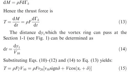
One can note here that expressions (11) and (15) can be compared to similar expressions in Glauert’s theory. The conditions (11) are similar to Glauert’s conditions for the disk inplane and far-field sections. However, in Shaidakov’s theory the expressions(11)and(15)are written for the velocity vector along the y1axis, unlike Glauert’s theory, where the similar conditions are formulated for the normal to the rotor disk v10nand v20ncomponents (see, for example, Padfield33):

In a general case, when the load (‘‘pressure jump” across the disk surface) Δp on the lifting system surface is not constant the plate F can be divided on a set of elementary plates dF. In this case


2.5.AD theory,based on a‘‘typical”circulation distribution and disk surface averaged loading (model AD4)


Fig. 2 Gaussian contribution function for VBA model.


Fig. 3 Geometry of PSP model rotor with 60% taper and 30°swept tip.36

Table 1 Meshing parameters for PSP rotor mesh.

Fig. 4 Computational domain and boundary conditions employed and topology of PSP rotor blocking.

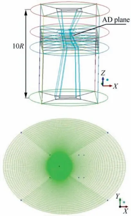
Fig. 5 Computational domain, multi-block topology and a section of CFD mesh for AD computations.
3. VBA model implementation
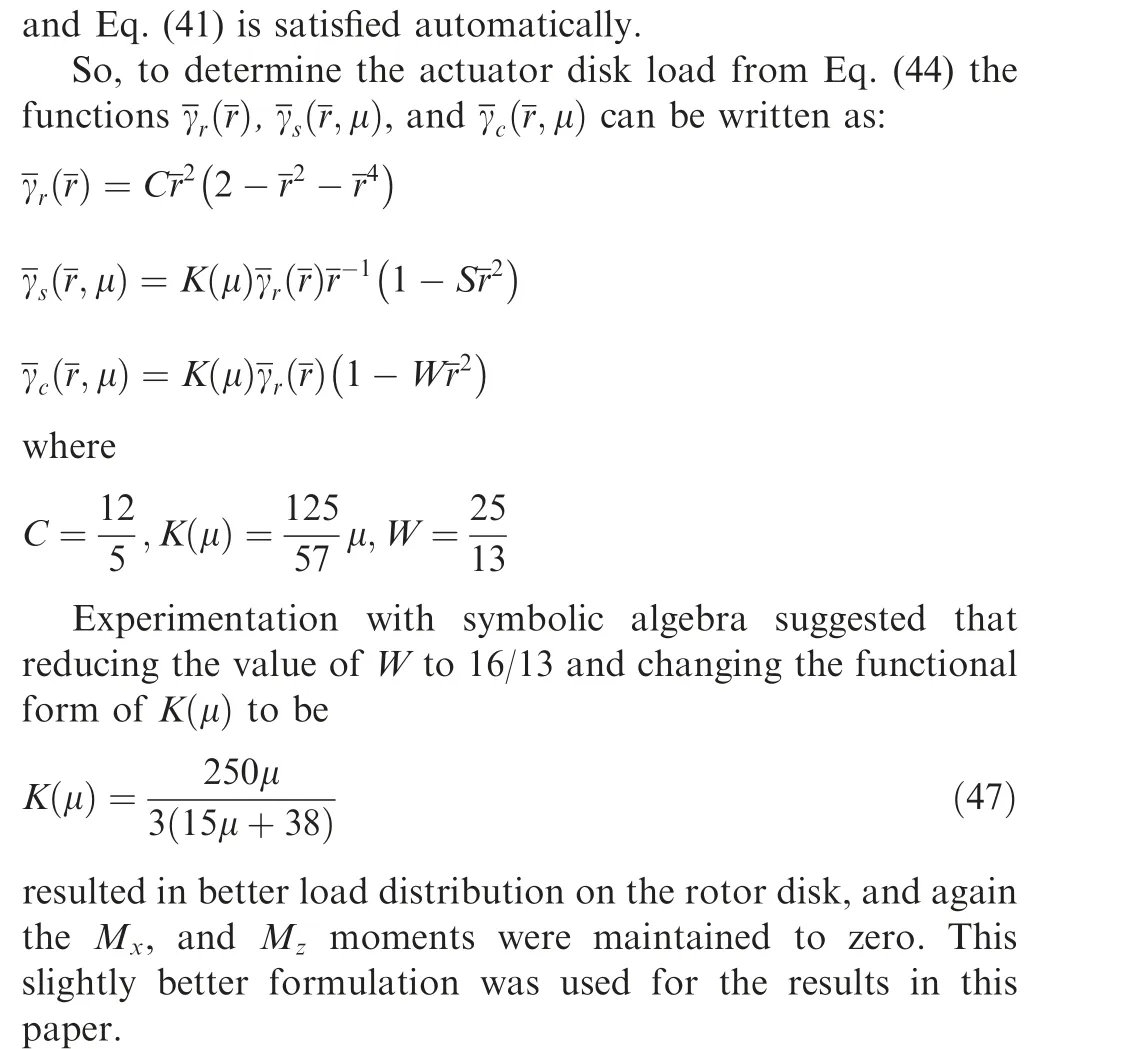
To introduce the effect of the rotating blades and to describe in more detail the rotor wake, the VBA model has been implemented in HMB3. For embedding of the AD models the local refinement of the grid cells using is accomplished using an additional grid splitting at a place of the disc localization.The virtual blades loading is distributed on the available grid cells.This allows for minimization of CPU time for determination of grid cells participating in a process of disk load distri-

Fig. 6 Visualization of hovering rotor flow using with the Qcriterion at symmetry plane section and location of vortex cores compared with the Kocurek & Tangler42 model.


Fig. 7 FoM for PSP model rotor at blade-tip Mach number of 0.585.

Table 2 Computational cases for AD and CFD models.

Thus,the cell distribution on the grid does not influence the global load of the rotor disk. Weighting in this way the effect of each point of the actuator disk,the presence of the blades is accounted for.
4. Numerical simulation of PSP rotor aerodynamics
To demonstrate the AD models presented in the previous paragraphs the isolated PSP model rotor blade is used with the HMB3 CFD solver34of Glasgow University.
4.1. PSP rotor geometry
The four-bladed PSP rotor has an aspect ratio (R/c) of 12.2 and a nominal twist of -14°. The main characteristics of the rotor blades are summarized in Table 1. The blade planform has been generated using three radial stations. First, the RC(4)-12 aerofoil was used up to 65%R.Then,the RC(4)-10 aerofoil from 70%R to 80%R. Finally, the RC(6)-08 aerofoil was used from 85%R to the tip.The aerodynamic characteristics of these aerofoils can be found in Refs. 35,36. The planform of the PSP model rotor has a 60% tapered and 30° swept tip and the details on the blade radial twist and the chord distributions are shown in Fig. 3.

Fig. 8 Rotor disk air loads normal force Ma2tip coefficients in forward flight at advance ratio μ=0.35, CT =0.008 (left column), and CT =0.016 (right column) for different AD models and fully resolved blades.
4.2. PSP rotor mesh

Fig. 8 (continued)
For the blades, a C-topology around the leading edge of the blade was selected, whereas an H-topology was employed at the trailing edge.37For hover computations, only a quarter of the computational domain was meshed, assuming periodic conditions for the flow field in the azimuthal direction. This assumption is valid if the wake generated by the rotor is assumed periodic and the blades do not experience stall. The multi-block structured grid for the PSP rotor in forward flight has a total of 31.6 million cells with 1968 blocks, with 20 million and 11.6 million cells for the background and body-fitted grids,respectively.A hub is also included in the computational domain and modeled as a generic ellipsoidal surface.A view of the computational domain along with the employed boundary conditions for hover is given in Fig. 4.

Fig.9 AD3 and AD4 models compared to fully-resolved blades for the CnMa2tip coefficients in forward flight at advance ratio μ=0.35, CT =0.016.
The size of the employed computational domain and the multi-block mesh topology for AD simulations are presented in Fig. 5. The domain is similar in dimensions to what was used for the fully resolved rotor. The multi-block structured grid for the AD model in forward flight had a total of 9 million cells with 63 blocks and 13.5 million cells in hover. The multiblock structure in hover mode was adjusted for reproducing of the rotor tip vortex wake.
The meshing parameters for the PSP mesh rotor blade along with the grids used for hover and Forward Flight (FF)cases are shown in Table 1.
4.3. Test conditions and computations

Fig. 10 Wake-visualisation of PSP rotor in forward flight at advance ratio μ=0.35 and CT =0.008 using-criterion (value of 0.002) for different rotor blades models.
In hover, the PSP blade was simulated at the blade-tip Mach number of 0.585. As a means to validate the PSP technique for rotor blades in hover, Wong et al.38and Watkins et al.39measured Cpat two radial stations at blade-tip Mach number of 0.585 on the PSP rotor blades, which were installed on the modified ROtor BOdy Interaction fuselage (ROBIN Mod7).Recently Overmeyer and Martin40extended this hover tests,measuring integrated blade loads for free and fixed transition and transition locations using the same conditions in the same facility (rotor test cell at the NASA Langley Research Center 14 ft×22 ft Subsonic Wind Tunnel). This hover condition is simulated here in Out-of-Ground Effect (OGE) conditions for six blade pitch angles. Moreover, the effect of turbulence models on the integrated loads is also evaluated at fixed blade pitch angle (θ75=12°). The Reynolds number, based on the reference blade chord crefof 5.45 inches and on the blade-tip speed, was 1.05×10⁶.
Fig. 6 presents simulation results after 4 revolutions in hover for the AD3 model at blade-tip Mach number of 0.585, and CT=0.016. Fig. 6(a) shows visualization of the flow field using the Q-criterion41at the symmetry plane. The location of the tip vortex cores at different flow sections is presented in Fig. 6(b) in comparison to the Kocurek and Tangler’s42model. The comparison suggests that the Kocurek and Tangler’s model agrees with simulation results especially for the early wake age.

Fig.12 Vorticity at 3 planes behind PSP rotor in forward flight at advance ratio μ=0.35 and CT =0.008 for the resolved(left column)and AD3 (right column) models.
The PSP main rotor was also simulated at forward flight.34Flight test data for forward flight was acquired by Wong et al.43at the 14 ft×22 ft subsonic tunnel at the NASA Langley Research Center on the General Rotor Model System(GRMS) test stand.44The rotor advance ratio was μ=0.35,and the free stream Mach number was 0.2. To meet the target thrust coefficient (blade loading coefficients CTof 0.008 and 0.016) while having zero roll and pitch moments, a matrix trimming method is used in HMB,14based on the BET for computing the elements of the sensitivity matrix. The flow solutions were computed solving the URANS equations, coupled with Menter’s19k-ω SST turbulence model. The employed time step corresponds to 0.25° in the azimuthal direction and was based on experience gained with previous rotor computations in forward flight.45
Fig.7 shows the variation of Figure of Merit(FoM) vs the blade loading coefficient, at six blade pitch angles, covering low, medium, and high thrust. Comparison with experimental data (opened squares) by Overmeyer and Martin40for the fixed-transition, 5%c, upper and lower (Run 156) and momentum-based estimates of the FoM(dashed lines)are also included. For the momentum-theory estimation, and induced power factor kiof 1.15 and overall profile drag coefficient CD0of 0.01 were selected. The presented solutions agree very well with published solutions from several sources including Wong46who used the unstructured solver FUN3D and the Spalart-Allmaras16turbulence model, Vieira et al.47who employed commercial CFD, and Jain48who used the OVERFLOW solver. Note that the experiments reported here do not correspond to an isolated PSP rotor, and were obtained with a helicopter fuselage in place. Therefore some degree of discrepancy on the air loads is expected.
Ref. 49 shows in detail the numerical simulation results for the PSP and other rotors in hover and forward flight.
4.4.Comparison of simulation results for AD and resolved CFD models


The CFD results for both AD models capture well the main flow structures near and far of the rotor disk compared to the fully resolved blades case. One can note a different near-field vortex shape for the uniform and non-uniform VBA models.This is due to the more loaded (virtual) blade tip part and underloaded middle part. The tip vortex core size for the uniform AD load is also predicted slightly smaller than for the non-uniform AD3 model.
To further show the differences and similarities between the employed models,the vorticity field is used.Fig.12 shows(for low thrust case) comparisons between the resolved blades and the unsteady AD for 3 planes at 0.5R, 1.0R and 1.5R.Although the results do not fully agree (as expected due to the differences in the fidelity of the methods) a similar range of values is seen for vorticity, several of the vortical structures are at similar locations. The lack of any thickness of the AD,and the lack of the exact loading and planform of the blade are the main reasons behind any differences.Nevertheless,at 1.0R behind the rotor, the wakes are not too dissimilar in overall structure and magnitude and the results of the AD method can be seen as a first approximation to a complex flow field.
Much the same way, comparisons for the high thrust case of the PSP blade can be seen in Fig.13.Again vorticity is used and the resolved blades are compared with the unsteady AD model. The main differences are concentrated on the extend of the vortical structures. So close to the rotor, the wake is not yet configured as a disk with two tip vortices.The distribution of the blade load using the Gaussian law and the assumed blade shape of the AD method obviously play a key role.Nevertheless, given the efficiency of the method this is something to be tolerated.The AD even in unsteady mode requires fewer grid points and for the PSP computations savings in CPU time approach 100%.For the considered AD mesh taking a revolution with 360 iterations 72 h are consumed by using 24 processors compared to 192 h by 72 processors for the fully resolved blades rotor. Clearly the AD method is an approximation but it can provide interesting results for first approximations to flows with rotor wakes.
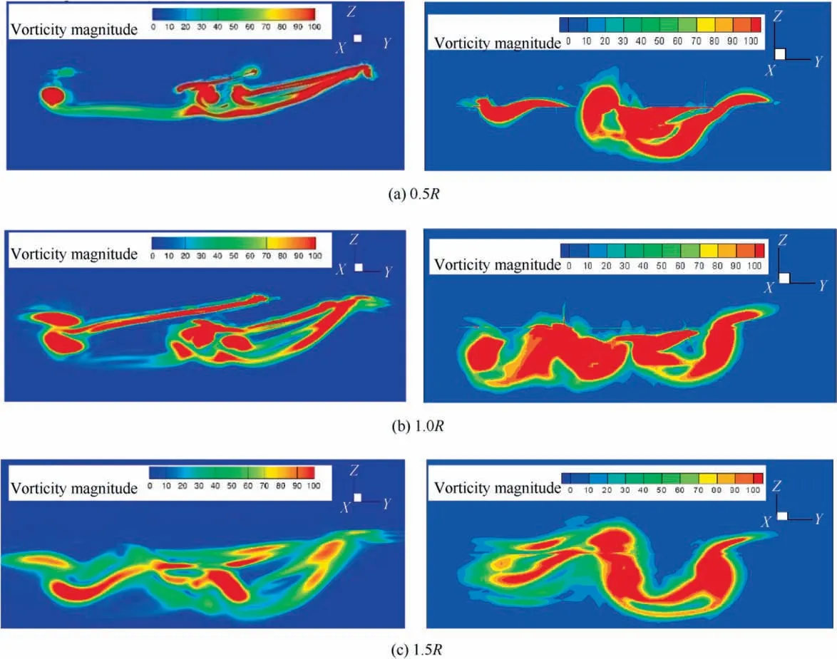
Fig.13 Vorticity at 3 planes behind PSP rotor in forward flight at advance ratio μ=0.35 and CT =0.016 for the resolved(left column)and AD3 (right column) models.
5. Conclusions
The AD approach was applied to flows around helicopter main rotors. Several actuator disk formulations were considered with uniform and non-uniform disk loadings. The nonuniform ADs were based on prescribed disk circulation distributions (including blade element theory). Simulations with fully resolved blades were compared to unsteady AD implementations, to allow resolution of the unsteady rotor wake.Despite the reduced grid cells number, the CFD results for AD models captured well the main vortical structures around the rotor disk in comparison to the fully resolved cases. These AD models can be used for studies of the flow wake or for simple studies of rotor installation effects. Efforts to deliver trimmed ADs suitable for dynamic computations are currently underway.
Acknowledgements
This study was co-supported by the grant ‘‘State task of the Education and Science Ministry of Russian Federation”agreement (No. 075-03-2020-051/3 from 09.06.2020, theme No.fzsu-2020-0021).
杂志排行
CHINESE JOURNAL OF AERONAUTICS的其它文章
- A new fatigue life prediction model considering the creep-fatigue interaction effect based on the Walker total strain equation
- State estimate for stochastic systems with dual unknown interference inputs
- Machining deformation of single-sided component based on finishing allowance optimization
- Type synthesis of deployable mechanisms for ring truss antenna based on constraint-synthesis method
- A hybrid lattice Boltzmann flux solver for integrated hypersonic fluid-thermal-structural analysis
- Positioning error compensation for parallel mechanism with two kinematic calibration methods
