Fault diagnosis method for switch control circuit based on SVM-AdaBoost
2020-08-25WANGDengfeiCHENGuangwuXINGDongfengLIANGDoudou
WANG Deng-fei,CHEN Guang-wu,XING Dong-feng,LIANG Dou-dou
(1. Automatic Control Research Institute, Lanzhou Jiaotong University,Lanzhou 730070,China;2. Gansu Provincial Key Laboratory of Traffic Information Engineering and Control, Lanzhou 730070, China)
Abstract:In order to realize the fault diagnosis of the control circuit of all-electronic computer interlocking system(ACIS)for railway signals, taking a five-wire switch electronic control module as an research object, we propose a method of selecting the sample set of the basic classifier by roulette method and realizing fault diagnosis by using SVM-AdaBoost.The experimental results show that the proportion of basic classifier samples affects classification accuracy, which reaches the highest when the proportion is 85%.When selecting the sample set of basic classifier by roulette method, the fault diagnosis accuracy is generally higher than that of the maximum weight priority method.When the optimal proportion 85% is taken, the accuracy is highest up to 96.3%.More importantly, this way can better adapt to the critical data and improve the anti-interference ability of the algorithm, and therefore it provides a basis for fault diagnosis of ACIS.
Key words:all-electronic computer interlocking system(ACIS);switch control circuit; support vector machine(SVM);AdaBoost;fault diagnosis
0 Introduction
Nowadays, the railway station signal control system have entered the stage of vigorous development of the fourth generation all-electronic computer interlocking system(ACIS)[1], which can implement the interlocking function of station signal equipment by electrical or electronic equipment.In this research, taking the control circuit of five-wire switch all-electronic control module(switch module)[2]in ACIS as a research object, the fault diagnosis method is studied by using a large amount of historical operation and debug fault data.
As an important part of ACIS, switch module can realize all-electronic real-time control of the switch.Because of large operation current and electromagnetic interference, the fault frequency of the control circuit of switch module is high.In ACIS, switch module acts as real-time security systems, in which the relationship between multiple performance parameters is complex and the fault has random uncertainty and fuzziness, therefore the fault is difficult to distinguish.At present, diagnosis of the ACIS mainly relays on artificial experience.Researchers also have paid attention to intelligent diagnosis methods of control circuit[3], such as neural network[4-5], support vecotr machine(SVM)[6], Bayesian network[7], etc.However, there is no successful application in fault diagnosis of ACIS.Therefore, it is of great significance to study the intelligent fault diagnosis method of control circuit based on multi-performance parameters for production debugging and fault repairing of ACIS, as well as to improve the intelligence of railway signal control system.
Adaboost[8]can adaptively adjust the accuracy of the classifier by choosing the samples of the basic classifier in the way of maximum weight priority, which changes the data distribution of training samples.Each iteration will obtain a basic classifier with the best classification and its weight in the overall classifier.As iterations increase, the final strong classifier generated by the basic classifier iteration has the smallest classification error, while SVM[9]has greater advantages in solving small sample, non-linear and high-dimensional problems.In this paper, based on the fault data accumulated by switch module in ACIS for a couple of years, a method of selecting basic classifier samples by roulette method and diagnosing them by combining the advantages of SVM and AdaBoost algorithm[10]is proposed, and then the fault diagnosis simulation of switch module control circuit is carried out.The results show that it can provide a basis for fault diagnosis of ACIS.
1 Analysis of switch module control circuit
Switch module drives AC five-wire switch machine to control the switch.The operation circuit structure is shown in Fig.1.The circuit interfaces X1, X2, X3, X4 and X5 are control wires connected with the switch machine through the distributor to realize switch driving and state acquisition.A, B and C are three-phase power source, K1 to K7 are electronic control switches.Besides, main switch breakdown inspection circuit, phase supervision device and current detection circuit are set up to monitor the working state of the circuit in real time.
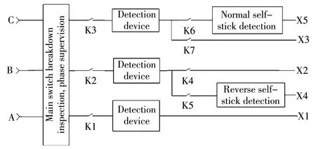
Fig.1 Structure diagram of switch module main operation circuit
The operating flow of switch operation circuit is as follows: When the switch is in reverse position and the switch module receives the normal operation command from interlocking system, switches K1, K2, K3, K4 and K6 are turned on and then X1, X2 and X5 are connected, which drives the switch machine to rotate towards normal position.When the switch is in normal position and the switch module receives reverse operation command, switches K1, K2, K3, K5 and K7 are turned on and then X1, X3 and X4 are connected, which leads to phase conversion and drives the switch machine to reverse position.
Switch module indication circuit structure is shown in Fig.2.It consists of transformer, current limiting resistance R1, normal indication detection circuit, reverse indication detection circuit, power source for switch indication, etc.It can monitor the switch position in real time.
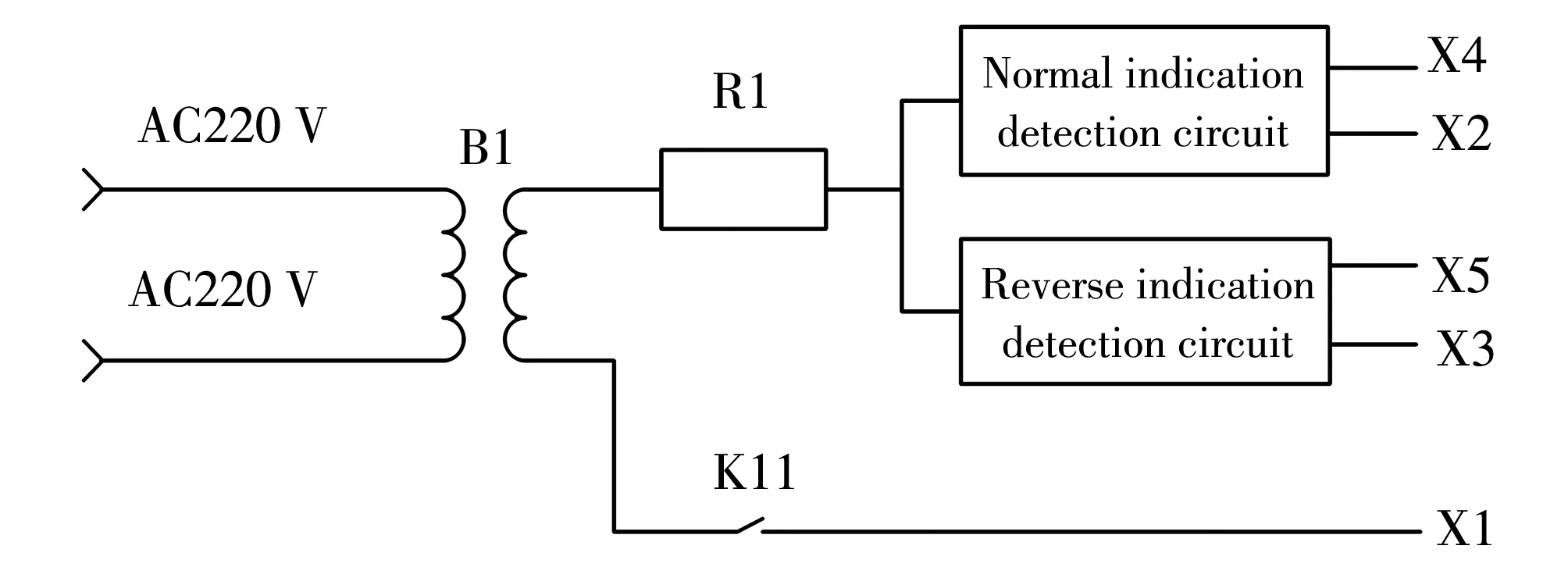
Fig.2 Structure diagram of switch module indication circuit
Indication diode, usually connected to the distributor, is the main component of the whole circuit.When it breaks down and is reversely connected, switch indication is lost, which can also effectively prevent X2 and X3 from reversing and resulting in error indication.Therefore, indication diode is an important component to ensure the normal operation of switch indication circuit, but its component characteristics lead to frequent faults of the whole circuit, therefore it should be included in the whole control circuit for fault analysis.
According to the features of the control circuit of switch module, the fault tree[11]is drawn, as shown in Fig.3.Ten types of failure modes are defined from A1 to A10, as listed in Table 1, which are represented by labels-5 to 5, respectively.
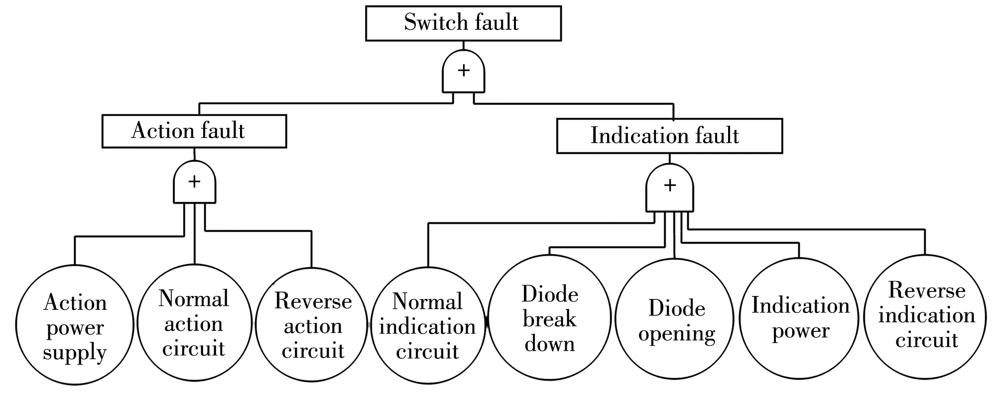
Fig.3 Fault tree of Switch module control circuit
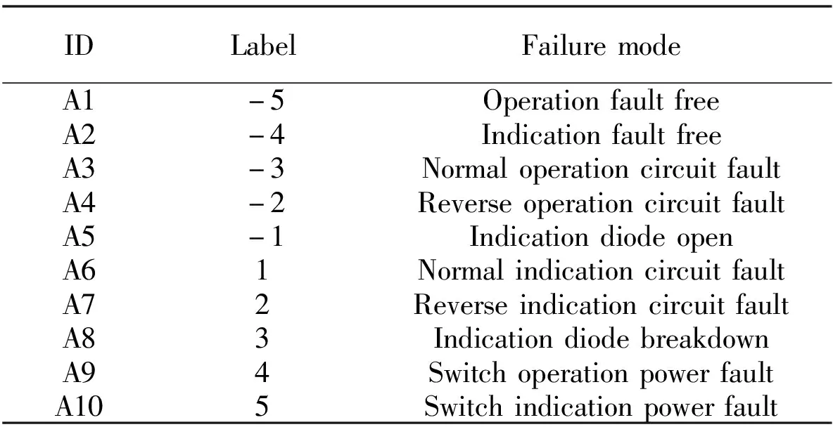
Table 1 Fault modes of Switch module control circuit
In order to diagnose switch module control circuit, 13 separated fault features are selected from ACIS and monitoring machine according to fault mode and cause analysis, as listed in Table 2, which are recorded as B1 to B13.

Table 2 Fault features description of switch module control circuit
Therefore, the fault diagnosis of switch module control circuit takes the fault features shown in Table 2 as inputs and the fault modes shown in Table 1 as outputs.
2 SVM-AdaBoost fault diagnosis method
The problem studied in this paper has the characteristics of small sample size, non-linearity and high dimension, therefore SVM is used as the basic classifier.AdaBoost[12]method can enhance the performance of classifier adaptively by superposition, but in the process of Adaboost training, the training is too biased towards such difficult samples, which makes the Adaboost algorithm vulnerable to noise interference.Because roulette algorithm can ensure that each sample has a certain probability of being selected to form a subset of the basic classifier, it can improve the anti-interference ability of the classifier.Therefore, roulette algorithm is used as the selection method of training sample subset of basic classifier, SVM-AdaBoost is used as fault diagnosis method, and switch module control circuit is taken to study the fault diagnosis method of control circuit of ACIS.
2.1 SVM
SVM[13]is a machine learning method based on statistical learning theory.It improves the generalization ability of learning machine by seeking the smallest structured risk, realizes the minimization of experience risk and confidence range, and achieves the goal of good statistical law in the case of fewer samples.
For a set of training samples
S={(xi,yi)},xi∈Rn,yi∈{1,-1},
(1)
wherexiis the data point,yirepresents the sample category.To classify the vast majority of samples correctly, the hyperplane should satisfy the requirement of maximizing the sum of the minimum distances from two types of sample points to the hyperplane.The expression of the hyperplane is given by
wTx+b=0.
(2)
wherewis the weight vector andbis bias of hyperplane.The distributions ofwandbare essentially linear, and non-linearity is caused by noise, that is, there are very few outliers far from the normal position.Using soft interval, good results can be obtained as
s.t.yi(wTxi+b)≥1-ξi,
ξi≥0,i=1,2,…,n,
(3)
whereξiis a slack variable and represents the number of function intervals of the data pointxiallowed to deviate from the hyperplane;c>0 is a penalty factor and presents the tolerance allowed to make mistakes.
For linear non-separable problems, the data are mapped to high-dimensional space by kernel function, and the SVM is extended to the non-linear separable case.Since Eq.(3)satisfies the karush-kuhn-tucher(KKT)condition, the above problem is transformed into
s.t.0≤αi≤c,
(4)
whereαiandαjare Lagrange coefficients andK(xi,xj)is the kernal function.Here, linear and Gaussian kernels are used, and their expressions are given by
K(xi,xj)=〈xi,xj〉,
(5)
(6)
The decision function can be obtained by
(7)
The above parameterscandδare determined by grid optimization method.
2.2 SVM-AdaBoost method
The core idea of AdaBoost algorithm is to increase the weight of error sample and to reduce the weight of correct samples, so as to train a new basic classifier under the new sample distribution.Thus several basic classifiers are obtained, and a strong classifier is formed by superimposing certain weights.
To improve the anti-interference ability of AdaBoost, the proportional coefficientKis set, andK-ratio samples are selected by roulette algorithm to form a subset of basic classifier samples in each iteration.
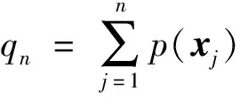
The basic idea of roulette algorithm is that the probability of a sample being selected is proportional to the value of its fitness function.If the sample size isNandfit(xi)is the fitness of samplexi, the selection probability ofxiis calculated by
(8)
Roulette process is as follows.
1)Produce a random numberRwith uniform distribution in an interval of[0,1].
2)IfR≤q1, samplex1is selected;
The training process of the SVM-AdaBoost algorithm[14]for selecting the sample set of the basic classifier by roulette method is as follows.
1)According to the training sample set
S={(xi,yi)},i=1,2,…,N,
(9)
we choose the proportionpof basic classifier samples to total samples, the iteration numberM, the exit accuracyA, and the individual fitnessfit(xi)of smaplexi, wherefit(xi)is the current weight of the samplexi.
2)Initialize sample weights
(10)
3)For the number of iterationsm=1,2,…,M,
① According to the current sample weightvm,i, the training sample subsetSm⊂Sof basic classifierGm(x)is obtained by roulette algorithm;
② Using the training data set with weight distributionvm, the basic classifierGm(x)is obtained by SVM learning.
③ The classification error rateemofGm(x)on the training data set is calculated by
(11)
④ The weight ofGm(x)in the final classifier is calculated by
(12)
whereαmdenotes the importance ofGm(x)in the final classifier, and its purpose is to obtain the weight of the basic classifier in the final classifier.
⑤ The weight distribution of the training data set is update by
(13)
(14)
wherezmis the normalization factor, makingvm+1obey a probability distribution.The updating increases the weights of the samples misclassified and reduces the weights of the samples correctly classified by the basic classifier.Thus, the AdaBoost method can focus on the more difficult samples.Then Eq.(12)is reduced to
(15)
whereyiGm(xi)=-1 represents that the sample is misclassified by the basic classifier, andyiGm(xi)=1 represents that the sample is correctly classified.
⑥ The training process is completed after the classification accuracy reaches the established thresholdAor iteration has performedMtimes.
4)The decision functionF(x)of the final classifier is obtained as
(16)
The algorithm classification process is described as follows.
1)Weak classifiers are cascaded into strong classifiers as
(17)
2)Substituting the sample values into Eq.(16), classification results are obtained as
(18)
The above process is a binary classification problem.To solve the multi-classification problem, a pair of multi-classification methods are used to construct a multi-classifier.The approach is to design a classifier between any two classes of samples, therefore thel-class samples need to designl(l-1)/2 classifiers.When classifying an unknown sample, the category that gets the most votes is the category of the unknown sample.
Selceting the samples of basic classifier by using roulette algorithm can ensure that the algorithm pays attention to the difficult samples, while smaller weight samples can also have a certain probability to participate in the training process, which improves the integrity of the basic classifier samples, makes the basic classifier after several iterations not completely concentrated on the difficult samples, and improves the anti-interference ability of the classifier.At the same time, the different sample sets ensure the heterogeneity of the basic classifier.
3 Simulation and analysis
Fault diagnosis is carried out by using 1 784 fault data accumulated from more than 400 railway stations and production debugging.The sample distribution is shown in Table 3.
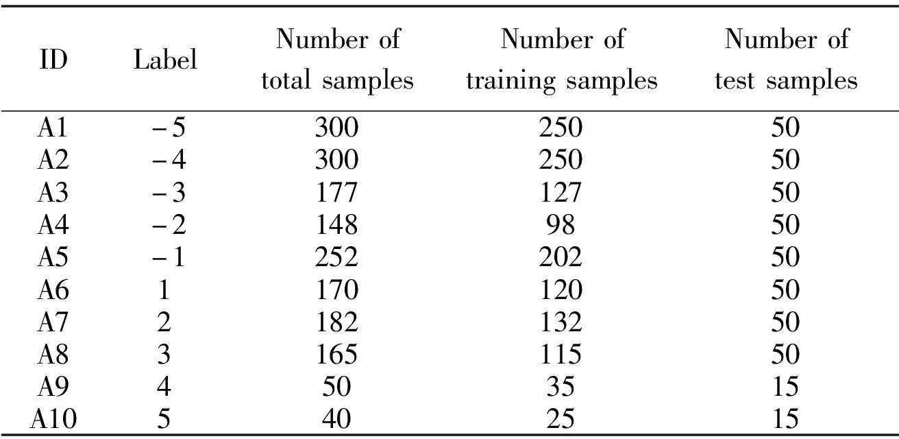
Table 3 Samples distribution of switch module control circuit faults
3.1 Samples acquisition of basic classifier
The basic classifier samples are selected by the maximum weight priority and roulette method, respectively.The two methods select all the unified samples and use SVM-AdaBoost to classify faults.The strategies are as follows.
1)When sample proportionpis 55%, 65%, 75%, 85%, 95% and 100%, respectively, the samples are trained.
2)The maximum weight priority method ranks the samples according to their weights, and takes the toppdata as the subset of the basic classifier.The roulette method chooses the sample subset in the roulette method described in Section 2.2.
3)SVM-AdaBoost is used to train the two way, and results are verified by test data, as shown in Fig.4.
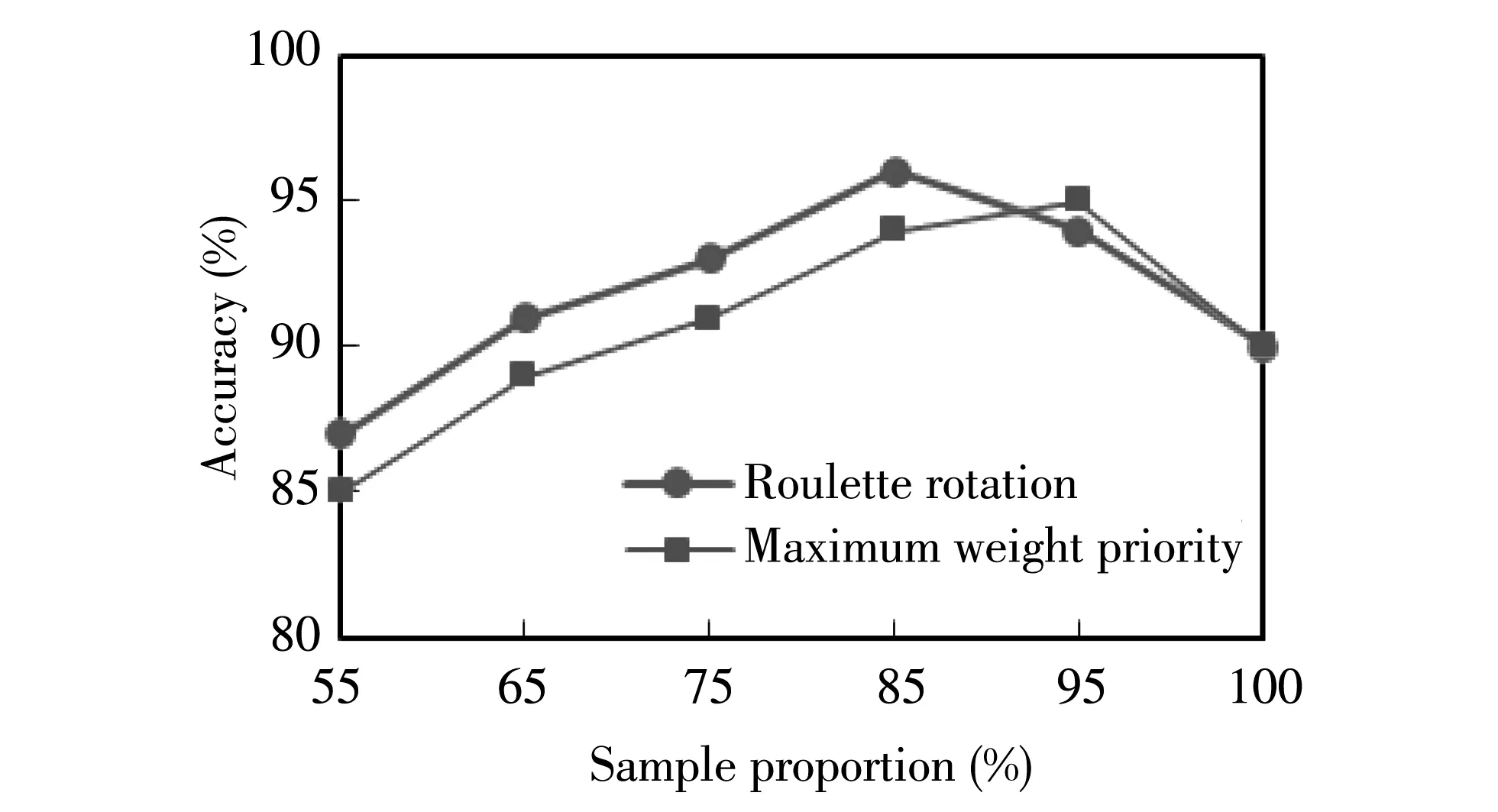
Fig.4 Impact of sample acquisition methods on basic classifiers
The experimental results show that the diagnosis accuracy of the classifier which uses roulette method is generally higher than that of the maximum weight priority method when the proportion of samples is less than 85%.Whenp>85%, the diagnosis accuracy of the maximum weight priority method is slightly higher than that of the roulette method, and whenp=85%, the SVM-AdaBoost algorithm has the highest diagnosis accuracy when the roulette method is used to select the basic classifier samples.Therefore, the optimal proportion isp=85%.
3.2 Analysis of fault diagnosis accuracy
The diagnosis experiments are carried out by using the methods shown in Table 4.Because of small sample size, SVM shows better accuracy than BP neural network.The average fault diagnosis rate of linear kernel SVM and BP neural network are approximately equal, about 80%.For Gauss kernel SVM, the optimal classification parameterscandδare chosen by grid optimization method.WhenCbest=4 andδbest=12.8, the classification result is the best,and the accuracy is 89.4%.

Table 4 Fault rate of Switch module control circuit
Linear kernel SVM has a strong ability to classify single feature fault such as operation power fault represented by A9 and indication power fault represented by A10, and all of them are classified correctly.Compared with linear kernel SVM, Gauss kernel SVM, which has higher fault diagnosis rate for other non-single feature faults.For A6, A7 and A8 fault modes, Gauss kernel SVM shows lower resolution than other modes because based on train station fault data, experienced engineers can hardly distinguish these three types of faults from the monitor data and curves.The average accuracy of Gauss kernel SVM is higher than that of linear kernel SVM and BP neural network method.
For the SVM-AdaBoost method, it uses roulette algorithm to select basic classifier samples.Taking into account the fact that linear kernel SVM has a high fault diagnosis rate for single fearture faults, the first basic classifier uses linear kernel SVM, and subsequently uses Gaussian kernel SVM.Each Gaussian kernel SVM uses grid optimization method to determine parameterscandδ.
Let the accuracy thresholdA=95%, the number of iterationsM=10, and then the experiment is carried out.When iteration performs 4 times, the accuracy meets the loop iteration exit request.At this point, the SVM-AdaBoost fault diagnosis result is shown in Fig.5, and the accuracy is up to 96.3%(414/430), which is much better than other methods.It is proved that this method has better resolution in Switch module control circuit fault diagnosis.
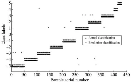
Fig.5 Fault diagnosis results of SVM-AdaBoost
3.3 Analysis of anti-interference capability
In the process of Adaboost training, the weight of difficult samples increases exponentially, and the training is too biased towards difficult samples, which makes the Adaboost algorithm vulnerable to noise interference.Furthermore, the control circuit is vulnerable to external complex environment interference, component performance degradation and other factors, which easily causes fault feature offset and fault feature data being at the edge of normal operating conditions, while such data are vulnerable to the performance of the algorithm.
As shown in Fig.6, non-switching features of switch module are selected to analyze the distribution of fault feature data.The data marked with circle is part of the data deviating from the normal value.The classification results show that this kind of data are easy to be misjudged by various classification methods in Table 4.Therefore, outliers far away from the most points in Fig.6 and the similar outliers artificially simulated are selected to form a test sample set with a total of 100 data.
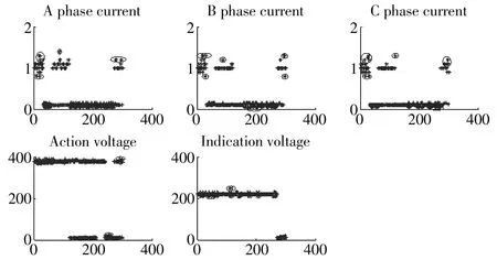
Fig.6 Characteristic data distribution of switch module control circuit
The experimental results are shown in Table 5.For this kind of samples, the accuracy of sample selection by roulette method is 14% higher than that by maximum weight priority way.

Table 5 Analysis of anti-interference ability of SVM-AdaBoost
Experimental results show that the method of fault diagnosis based on SVM-AdaBoost can better adapt to critical data and improve anti-interference ability when the sample set of basic classifier is selected by using roulette method.
4 Conclusion
In this paper, the SVM-AdaBoost method is used to diagnose the switch module control circuit of the ACIS.
The acquisition way of basic classifier sample set affects the diagnosis accuracy of SVM-AdaBoost.The diagnosis accuracy is generally higher than the maximum weight priority method by using the roulette method to obtain samples.Simultaneously, this method can better adapt to critical data and improve the anti-interference ability of the algorithm.
The proportion of basic classifier samples has a great influence on the accuracy of SVM-AdaBoost fault diagnosis.The proportion of samples can be determined by experiment according to the sample data.The fault diagnosis method based on SVM-AdaBoost for switch module control circuit has better accuracy.The research content can be applied to the fault diagnosis of ACIS.
杂志排行
Journal of Measurement Science and Instrumentation的其它文章
- An LFSR-based address generator using optimized address partition for low power memory BIST
- Influence of signal-to-noise ratio on accuracy of spectral analysis by near infrared spectroscopy
- Research on thermal decomposition of 1,3,5-trinitro-1,3,5-triazinane based on differential scanning calorimetry
- Underwater acoustic signal extraction algorithm in a strong noise environment
- An extraction method for pressure beat vibration characteristics of hydraulic drive system based on variational mode decomposition
- A method of remote sensing image water segmentation based on adaptive morphological elliptical structuring elements
