Failure envelope of a caisson foundation under combined vertical, horizontal and moment loadings
2020-07-20AbdellatifBoucheloukhGongWeimingDaiGuoliangZhuMingxing
Abdellatif Boucheloukh Gong Weiming Dai Guoliang Zhu Mingxing
(School of Civil Engineering, Southeast University, Nanjing 211189, China)
Abstract:To investigate the bearing capacity of a caisson foundation under combined vertical, horizontal and moment loadings, the three-dimensional finite element analyses of a circular caisson foundation in homogenous sandy soil subjected to combined loadings are conducted. The caisson model has a depth to breadth ratio equaling one, and a soil-caisson interface friction coefficient μ=0.3. First, the responses of caisson foundations under uniaxial vertical loading V, horizontal loading H and moment loading M are examined. Moreover, the responses of caisson foundations under combined vertical-horizontal V-H, vertical-moment V-M and horizontal-moment H-M load space are studied and presented using normalized failure envelopes generated by the load-controlled method. Subsequently, the bearing behavior of caisson foundations under combined vertical-horizontal-moment V-H-M load space, as well as the kinematic mechanisms accompanying the failure under uniaxial and combined loading, are addressed and presented for different vertical load ratios V/Vu. Finally, three equations that approximate the three-dimensional shape of the failure locus are proposed, which provides a convenient means of calculating the bearing capacity of a caisson foundation subjected to uniaxial and combined vertical, horizontal and moment loadings.
Key words:caisson foundation; failure envelope; finite element analysis; bearing capacity; sandy soil
In geotechnical engineering, hydraulic engineering, coastal and deep-water engineering, foundations are usually subjected to vertical loading with a long-period acting and simultaneous or cyclic loading components including horizontal loading and moment loading. The vertical loadingV, horizontal loadingH, and moment loadingMcan be transferred to the underground soil layers through the foundation beneath the building. Such a loading mode is defined as the combined loading mode. The prediction of the ultimate load capacity of such foundations carrying vertical, horizontal and moment loads is a fundamental engineering problem. In the recent two decades, many researchers attempted to find the closed form of the failure envelope locus and to derive the ultimate bearing capacity of the deep-water foundation under combined vertical, horizontal and moment loadings based on experimental laboratory small scale model tests and finite element analysis programs[1-6]. The failure envelope is defined as a convex curved face in vertical, horizontal and moment loading space when the general shear failure mode occurs.
The failure envelope of shallow foundations undergoing combined vertical, horizontal and moment loadings has become a fundamental soil mechanics research problem. Researchers recently analyzed the combined loading responses of shallow foundations by means of plasticity methods. The failure envelope inV-H-Mload space and yield surface equations has been deduced for different foundation systems. A general review of different proposed three-dimensional yield surface equations of foundations installed in different soil types and subjected to combinedV-H-Mloadings is presented in the following.
For any foundation, there is a three-dimensional yield surface equation containing all combinations of loadsV,H, andM, which represents a failure envelope for the foundation. Any combination of loads inside the failure envelope equation can be regarded as a safe load combination for the foundation. This idea has been supported at the model scale by a large number of experiments on shallow strip footings on the sand by Butterfield and Gottardi[7]. They showed a simple three-dimensional failure envelope inV-H-Mload space and defined the failure envelope as the location of the end-points of all conceivable load paths to the failure of footing. The failure locus on theV-Hplane or theV-Mplane is a parabolic curve whereas on theH-Mplane, at a vertical load ratioV/Vu=0.5, the failure locus is an ellipse rotated through an angle of 13° from theHaxis toward the negative direction of theMaxis.
A finite element study of the failure locus for strip foundations on non-homogeneous undrained clay under combinedV,H, andMloading was proposed by Bransby and Randolph[8]. New information has been obtained about the shape of the yield locus and the soil deformation mechanisms at yield from the finite element analyses. The shape of the yield locus was found to be similar to that predicted by previous workers inV-HandV-Mload spaces but differed significantly inH-Mload space. The soil deformation mechanisms calculated in the finite element analyses were supported using upper-bound plasticity mechanisms. A three-dimensional equation that approximates the shape of the yield locus is suggested, with a simplifying transformation for the yield locus inH-Mload space. The transformation of the yield locus inH-Mload space is obtained by the function of the height of the rotation center above the base when foundations become unstable under the pure moment.
Taiebat and Carter[9]presented a series of three-dimensional finite element analyses in order to investigate the failure envelope of circular foundations on the surface of homogeneous, purely cohesive soil subjected to combinedV-H-Mloadings. They showed two and three-dimensional failure envelopes in the non-dimensional space for foundations under combined loads and moment, based on numerical predictions. A three-dimensional equation that approximates the shape of the failure locus was also suggested to deal with the bearing capacity of these foundations. In the formulation of this equation, the moment capacity of the foundation is related to the horizontal load acting simultaneously on the foundation.
Loukidis et al.[10]presented a series of two-dimensional finite element methods to determine the collapse load of a rigid strip footing placed on a uniform layer of purely frictional soil subjected to eccentric and inclined loading. Two series of analyses were performed, one using an associated flow rule and one using a non-associated flow rule. Both probe-type analyses and swipe-type analyses were undertaken. Three different equations are proposed to predict the three-dimensional failure envelope of these foundations subjected to combinedV-H-Mloadings. The failure locus on theV-Hplane or theV-Mplane is a parabolic curve whereas on theH-Mplane, at different vertical load ratios, the failure locus is a rotated ellipse. The elliptical equation parametersH|e=0andM|α=0are equal to theHandMvalues yielded by the equations used to predictV-HandV-Mcross-sections, respectively.
In the present study, a series of three-dimensional finite element analyses using the ABAQUS program are performed to investigate the shape and locus of the failure envelope of a caisson foundation installed into homogenous sand soil, where the foundation embedment ratioD/B=1.0, and the soil caisson interface condition friction coefficientμ=0.3. The capacities of caisson foundations under combinedV-H,V-MandH-Mload spaces are studied and expressed by failure envelopes. Different failure mode mechanisms that occurred during the system (soil-foundation) failure are investigated and presented in this work. Finally, equations are proposed to predict different cross-sections of the failure envelope of a caisson foundations under combinedV-H-Mloadings.
1 Numerical Modelling
1.1 System soil-foundation geometries
The simplified analysis of the numerical modeling results provided a basis for developing the relationships between different applied vertical, horizontal and moment loads in the form of a complete failure surface inV-H-Mspace.
To investigate the failure envelope of a caisson foundation under combined vertical, horizontal and moment loadings, a three-dimensional finite element simulation was carried out using the ABAQUS program on a circular concrete caisson foundation embedded in homogeneous sandy soil. The caisson foundation embedment ratio isD/B=1, and the soil-caisson interface friction coefficient isμ=0.3. Fig.1 shows the modeled caisson foundation. The depth of the caisson foundation is considered to be constant and equals 9.0 m. The outside diameter of the caisson is 9 m, and the wall thickness is 0.25 m. The inside diameters vary from 4.8 to 5.2 m. The thickness of the lower part (tip-face) of the caisson is 0.4 m. The geometrical dimensions of the surrounding sand soil (see Fig.2) depend on the boundaries conditions which are placed far enough to avoid its influence on the different soil deformation mechanisms mobilized during the system’s failure and defined as length×width×depth (40 m×40 m×40 m).
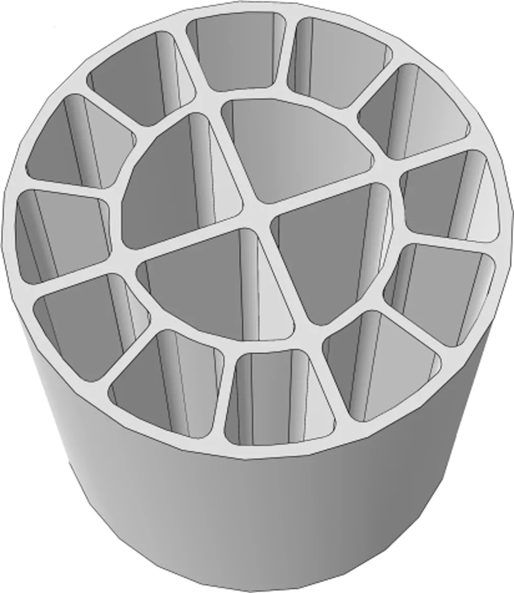
Fig.1 Caisson foundation model

Fig.2 Mesh of the finite element model(unit:m)
1.2 Sand soil and caisson foundation properties
In the analysis, the sandy soil cohesionc=0.5 kPa; the frictional angleφ=20°; elastic Young’s modulusEand Poisson’s ratioνare 80 MPa and 0.3, respectively. The mass density and the dilatancy angle of sand soil are 1 800 kg/m3and 0°, respectively. In the concrete caisson foundation, the mass density is 2 500 kg/m3, elastic Young’s modulusE=30 GPa and Poisson’s ratioν=0.2.
1.3 Contact modeling
The interface conditions between deep foundations and the surrounding soil are defined by interaction properties in normal and tangential behaviors. However, the caisson is connected to the soil with special contact surfaces (using the Master-Slave option), allowing for realistic simulation of possible detachment and sliding at the soil-caisson interfaces. The normal behavior or the surface-to-surface contact interaction was modeled by hard contact pressure-overclosure formulation, and the hard contact formulation shows that no contact pressure is transmitted without contact between the surfaces. Also, there is no limit to the contact pressure that can be transmitted when the surfaces are in contact. The hard contact formulation can be used along with the augmented lagrange, penalty and direct standards; i.e., the constraint enforcement method is selected as default in this study, and the separation contact between the respective surfaces is allowed all the time. The tangential behavior or the slippage of the caisson along the interfaces is governed by Coulomb’s friction law by appropriately assigning friction coefficientμ.
1.4 The finite element mesh
The finite element mesh used in the analysis is shown in Fig.2. A thin layer of continuum elements was used in the region of the soil-caisson interface to improve the prediction of the response of the caisson with the surrounding soil. The mesh comprises of 13 989 hex elements for both soil and caisson instances with the element type of C3D8R: an 8-node linear brick, reduced integration, and hourglass control.
1.5 Load paths
Three different steps are followed in this analysis to simulate the actual field conditions. In the first step, the numerical simulation soil undergoes geostatic loading. In the second step, part of the sand soil will be removed and replaced by the caisson foundation.The third step is defined as the load step, in which the caisson foundation will be subjected to a vertical load applied at the load reference pointPref, as shown in Fig.3.
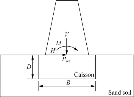
Fig.3 Model of a caisson foundation under general loading mode
In this work, the failure modes of the foundation are investigated by the load-controlled method. The loading was started with a single vertical load applied at the reference point on the top face of the caisson foundation and was increased gradually until failure was reached. Afterward, multiplying the vertical load by different ratios varying from 0.8 to 0 and applying another horizontal load or bending moment at the same load reference pointPrefwas done to obtain a vertical horizontalV-Hor a vertical momentV-Mplane, respectively. When the vertical load ratio equals zero, the foundation is then under pure horizontal or pure moment loading.
For the vertical, horizontal and moment loadV-H-Mspace, the applied vertical failure load was reduced and multiplied by a vertical load ratio of 80%. Then a moment loading was applied at the same load reference point and increased gradually until failure was reached. This failure moment loading was multiplied by different ratios varying from 0.8 to 0 (for positive load combinations), and varying from zero to more than one (for negative load combinations). Then, another horizontal load was applied at the same reference pointPrefand increased gradually until failure occured. The shape of theV-H-Mfailure envelope was identified when the vertical failure load was reduced to more ratios varying from 80% to 0%. When the applied vertical load reduced to 0%, the foundation is then underH-Mloadings.
2 Results and Analysis
2.1 Vertical bearing capacity
The load-settlement curves were used to determine the vertical bearing capacity of the caissons.Fig.4(a) shows the load-settlement results obtained by the finite element analysis of the caisson under pure vertical loads plotted against the vertical displacements, where the depth to breadth ratioD/B=1, and the interface friction coefficient between the caisson and surrounding soil isμ=0.3.
The present results show that the load-settlement curve of the caisson foundation deflected gradually without the inflection point. This failure mode corresponds to a punching failure mode, and the vertical ultimate bearing capacityvudepends on the foundation settlement. From Fig.4(a), we can see that the vertical bearing capacity cannot be reached even when the caisson displacement is larger than 0.3B. Wang and Jin[11]studied the failure loci of suction caisson foundations under combined loading conditions and defined the vertical load capacities as the cut-off values, or the load corresponding to a vertical settlement of 0.05B. Liu et al.[12]defined the vertical load capacity where the vertical settlement is equal to 0.06B, andBis the diameter of the caisson foundation. In order to ensure the normal function of the caisson foundation, the ultimate vertical loading corresponding to 0.05Bwas taken as the ultimate bearing capacityvu.
Fig.4(b) shows the undeformed shape of the failure mechanism of this caisson foundation under pure vertical loading by incremental displacement vectors at the point of failure for the caisson foundation. The failure mechanism of a caisson foundation penetrating into sand soil is significantly different from shallow footings resting on sandy soil. Caissons translate vertical and lateral loadings from the top of the caisson to the surrounding lateral soil in front of the caisson and the underlying soil at the tip surface level. Shallow footings resting on sand soil translate vertical and lateral loadings from the top of the foundation to the underlying soil at the tip surface level only.

(a)
2.2 Horizontal bearing capacity
Fig.5(a) shows the behavior of load-displacement results obtained by the finite element analysis of the caisson under pure horizontal loads plotted against the horizontal displacements. Fig.5(b) shows that the failure mechanism of the caisson foundation is under pure horizontal loading by incremental displacement vectors at the point of failure for the caisson foundation. Based on the terminology introduced by Gerolymos et al.[13], the failure mechanism observed for the caisson foundation under pure horizontal loading is classified as a scoop slide mechanism. But in this study, the failure mode is similar to the scoop mechanism failure mode observed for the case when the foundation is under pure moment loading. The main reason for this is when the horizontal load is applied to the foundation, the rotation is not constrained. Thus, this failure mode that occurred can be classified as a scoop mechanism.

(a)
2.3 Moment bearing capacity
Fig.6(a) shows the behavior of the moment-rotational angleθ° curve and the ultimate moment capacitymuof the caisson foundation obtained by finite element analysis, where the caisson foundation bearing capacity under pure moment increases linearly. Fig.6(b) shows a snapshot of the failure mechanism of this caisson foundation under pure moment loading by incremental displacement vectors at the point of failure for the caisson foundation. According to the previous terminologies, the category of the failure mechanism observed under pure moment loading is classified as a scoop mechanism.

(a)
2.4 The failure envelope in VHM space
2.4.1 The failure envelope onV-Hplane atM=0
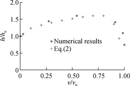
Fig.7 shows the cross-section of the failure envelope on theV-Hplane when the caisson foundation is under combined vertical and horizontal loads. The horizontal axis represents the vertical failure load componentsvnormalized by the ultimate bearing capacity of the caisson foundation under pure vertical loadvu, while the vertical axis represents the horizontal failure load componentshnormalized by the ultimate bearing capacity of the caisson foundation under pure horizontal loadhu. The verticalvand the horizontalhare failure load components, which are obtained as the ultimate verticalvuand horizontalhubearing capacities, respectively. In this figure, we can see that as the ratio of the vertical loadv/vuincreases, the ratio of the horizontal loadh/huincreases until it reaches a peak (h/hu)max=1.6. This maximum horizontal load coincides with a vertical load ratiov/vu=0.54. However, as the ratio of the vertical loads (v/vu) becomes significant, the ratio values of the horizontal loadsh/hureverse and decrease until they become zero. In other words, as the vertical components of the failure loadvapproaches the ultimate bearing capacity of the foundation under pure vertical load, the horizontal load capacity declines sharply until it is nullified.

Fig.7 V-H cross-section of the failure envelope obtained by numerical analysis results
2.4.2 The failure envelope onV-Mplane atH=0
Fig.8 shows the failure envelope of vertical and moment load combinations (V-M). The horizontal axis represents a ratio of the vertical failure load componentsvover the ultimate bearing capacity of the caisson foundation under pure vertical loadvu, while the vertical axis represents the ratio of the moment failure load componentsmover the ultimate bearing capacity of the caisson foundation under pure moment loadingmu. The verticalvand momentmfailure load components are estimated as the ultimate verticalvuand momentmubearing capacities, respectively. In Fig.8, we can also see that the maximum ratio of the normalized moment loading (m/mu)max=1.61 corresponds to a normalized vertical loading equal to 0.54. Also, when the values of the vertical load ratio vary from 0 to 0.54, the moment load ratios increase until they reach the maximum load (m/mu)max, while for the case when the vertical load ratios vary from 0.54 to 1, the moment load ratio decreases until it becomes nullified.

Fig.8 V-M cross-section of the failure envelope obtained by numerical analysis results
2.4.3 The failure envelope onH-Mplane atV=0
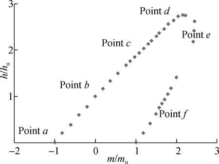
A series of numerical analysis on theH-Mplane withV/Vu=0 was performed. The failure envelope obtained from the analysis of the horizontal and moment loading is illustrated in Fig.9(a). We can see that theH-Mfailure envelope has a shape of half an oblique ellipse. In the case when the horizontal and moment act in a positive direction, the values of horizontal and moment load ratiosv/vuandh/huare less than or equal to one. While for the case when the horizontal and moment loads act in the opposite direction, the applied overturning momentMcounter balancing the applied horizontal loadHconfirms the efficiency of negative load combinations in increasing and enhancing the ultimate bearing capacity of the caisson foundation. For example, the horizontal and moment failure loads can reach their maximum valueshmaxandmmax, wherehmaxis 2.77 times higher than the bearing capacity of the foundation under pure horizontal load, andmmaxis 2.44 times higher than the foundation capacity under pure moment loading.
Fig.9(b) shows the normalizedH-Mfailure envelope corresponding to different vertical load ratiosV/Vu≥0. It is obvious that the failure envelope has a shape of a half oblique ellipse although there is influence from theV/Vuratio on the expansion of the failure envelope shown for the case whenV/Vu=0, i.e. the vertical load ratios increase the failure envelopes’ expanding untilh/huandm/muobtain their maximum values, where the vertical load ratioV/Vu=0.2. However, the failure envelope starts to reduce and shrink back when the vertical load ratioV/Vu
(a)
≥ 0.2. We can also see that the maximum horizontal and moment failure loads corresponding to a vertical load ratioV/Vu=0 are smaller compared to the enhanced horizontal and moment failure loads when the vertical load ratioV/Vu=0.2. Thus, to investigate the failure mode mechanisms of this foundation, we take into account the horizontal-momentH-Mcross-sections corresponding to vertical load ratiosV/Vuof 0 and 0.2, respectively.
2.5 Deformation mechanisms
Zafeirakos and Gerolymos[14]used a finite element analysis program to study the soil deformation mechanisms of a caisson foundation in frictional soil subjected to combinedV-H-Mloadings, with aD/Bratio varying from 1 to 3 and the interface friction coefficientμ=1. This study is similar to that presented by Gerolymos et al.[13]on caisson foundations in cohesive soil subjected to static and dynamic loadings. Gerolymos et al.[13]presented the contours of resultant displacement at failure and defined the location of the rotation poleZp(Zpis the distance from the load reference point to the center of the rotation of contours) to analyze different failure mode mechanisms corresponding to specific points on the horizontal-momentH-Mcross-sections (see Fig.9(a)).
To investigate different failure mode mechanisms in this study, we first focus on the horizontal-moment (H-M) cross-section corresponding to the vertical load ratiosV/Vu=0. Also, the terminology introduced by Gerolymos et al.[13-14]is used to classify different failure mode mechanisms.
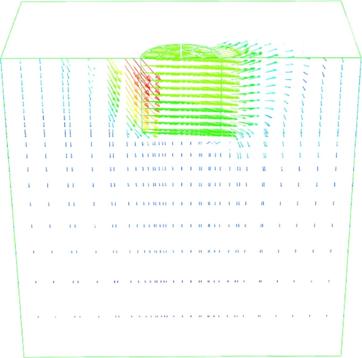
Fig.10 shows snapshots of the failure mode mechanisms corresponding to a vertical load ratioV/Vu=0. At pointa, a scoop mechanism is observed when the foundation is subjected to a pure moment loading as shown in Fig.10(a). Scoop mechanisms are developed between pointsaandc, similar to the case when the foundation is subjected to a pure horizontal loading (see Fig.10(b)). The rotation point of the vector displacement of different failure mode mechanisms was found to move from the lower-left part (under pure moment loading) to the lower-right part of the caisson (under pure horizontal loading).
At pointc, the location of the vector displacement rotation point appeared on the tip face of the caisson foundation as illustrated in Fig.10(c). This failure mechanism is called the inverted pendulum mechanism. At pointd, where the maximum horizontal load ratioh/huis attained, the location of the vector displacement rotation pointZpis defined by Zafeirakos and Gerolymos[14]to be infinity (see Fig.10(d)). At pointe, where the maximum moment ratiom/muis attained, the vector displacement rotation pointZpis located at a depth corresponding to a half embedment of the caisson foundation as illustrated in Fig.10(e). And finally, a reverse scoop mechanism appeared at pointfcorresponding to the remaining part of theH-Mcross section (see Fig.10(f)).

(a) (b) (c)
(d) (e) (f)
Figs.11 shows the snapshots of the failure mode mechanisms corresponding to a vertical load ratioV/Vu=0.2 by the incremental displacement vectors. Feld[15]studied the failure mode mechanism for combinedV-H-Mloading of the bucket foundation subjected to large vertical loads and defined three different failure mode mechanisms (shallow rotational failure, intermediate rotational failure, and deep rotational failure). The illustrated snapshot of the caisson foundation subjected to vertical and moment loadings corresponds to the intermediate rotational failure mode presented by Feld[15](see Fig.11(a)). The failure mode mechanism presented in this case is similar to that presented for the caisson foundation under pure moment loading, as shown in Fig.10(a). However, the rotation point of the vector displacement presented in Fig.11(a) seems slightly pushed down by the presence of the vertical load, i.e. the presence of the vertical load enhanced the bearing capacity of the moment loading up to about 70%, as shown in Fig.9(b).
A scoop slide mechanism is observed between pointsaandc, which is similar to the case that the foundation is subjected to a pure horizontal loading as illustrated in Fig.10(b). However, the rotation point of the vector displacement presented in Fig.11(b) was found to have moved from the right side to the left side of the caisson and being slightly pushed down by the presence of the vertical load. The presence of the vertical load enhanced the bearing capacity of the horizontal loading to about 60%, as shown in Fig.9 (b).
Fig.11(c) illustrates a failure mode mechanism, which is similar to the deep rotational failure presented by Feld[15]. In this case, the location of the rotation point of vector displacement appearing on the tip surface of the caisson (see Fig.10(c)) is moved from the right side to the left side by the presence of the vertical load. Fig.11(d) shows the failure mode mechanism corresponding to the maximum horizontal load of a caisson foundation under combinedV-H-Mloading with a depth to breadth ratio equaling 1, and the vector displacement rotation point seems to be infinity.
Fig.11(e) shows a maximum moment ratio (m/mu) of a caisson foundation under combined (vertical, horizontal and moment) loadings with a depth to breadth ratio equaling 1. In this case the vector displacement rotation pointZpis located at a depth corresponding to a half embedment of the caisson foundation. This failure mode mechanism is similar to the shallow rotational failure mode presented by Feld[15]. Finally, a reverse scoop mechanism at the remaining part of the failure envelope is presented in Fig.11(f).

(a) (b) (c)

(d) (e) (f)
2.6 General failure equations
This study aims to develop new formulas to predict the locus of the failure envelope of caisson foundations subjected to combined vertical-horizontalV-H, vertical-momentV-Mand horizontal-momentH-Mloadings.
TheV-H,V-MandH-Mcross-sections of the failure envelopes are obtained after normalization of the different vertical, horizontal and moment failure loads by the corresponding ultimate vertical, horizontal and moment loads, respectively. However, to better predict the results of the numerical analysis, a new equation is proposed to describe the shape of theV-HandV-Mcross-sections of the failure envelopes(see Figs.12(a) and (b)). This equation can be written as
(1)
wherev/vu,h/huandm/muare the vertical, horizontal and moment failure loadings normalized by their vertical ultimate bearing capacities, respectively.The values of the vertical ratiov/vuvary from 0 to 1.The parametersα1,α2,β1,β2andβ3take the values of 0.5,15,1,0.730 6 and 1.730 6 for theV-Hcross-section and 0.7,10, 1,0.907 3 and 1.907 3 for theV-Mcross-section, respectively.
After replacing different parametersα1,α2,β1,β2andβ3in Eq.(1), the equations used to predict the shape of the failure envelopes inV-HandV-Mplanes can be respectively rewritten as
(2)
(3)
Fig.12(c) illustrates the results of theH-Mcross-sections of the failure envelopes obtained after renormalization of horizontalhand momentmloads by horizontalh*and momentm*loads corresponding to a fixed vertical load ratioV/Vu, respectively. The proposed equation to predict the locus of theH-Mcross-sections can be written as
(4)
whereh*is the horizontal failure load corresponding to a fixed vertical load ratioV/Vuin theV-Hplane;m*is the moment failure load corresponding to a fixed vertical load ratioV/VuinV-Mplane; and the normalized horizontal and moment loadingsh/h*andm/m*can be calculated from Eqs.(2) and (3), respectively.
(a)
The approximating half elliptical expression describes the inner boundary of the failure envelopes at each level of the vertical load ratiov/vu, where the values of the vertical load ratio vary from 0 to 1. The results of the failure envelope corresponding to the vertical load ratioV/Vu=0.6 seems slightly eccentric along the major axis of the half oblique ellipse. Although the approximate half elliptical expression is proposed to give a good fitting of different load combinations scenarios, it seems slightly conservative when the failure envelope approaches the maximum valuesh/h*andm/m*.
3 Conclusions
1) The response of caisson foundations under pure vertical, horizontal and moment loadings, as well as the results of two-dimensional cross-sections of the failure envelopes of caisson foundations in vertical-horizontalV-H, vertical-momentV-Mand horizontal-momentH-Mcorresponding to different vertical load ratiosV/Vuwere presented and investigated. It is found that the presence of the vertical load atV/Vu=0.2 enhanced the horizontal and moment bearing capacities corresponding to the negative load combination plane to 60% and 70%, respectively.
2) The failure mode mechanisms of the caisson foundations under pure vertical, horizontal and moment loadings, as well as the accompanying failure mode mechanisms of different horizontal-momentH-Mload combinations were investigated and presented, where the vertical load ratiosV/Vuare of 0 and 0.2, respectively. Also, different failure mode mechanisms were defined according to the location of the rotation point of the incremental displacement vectors centerZp.
3) Three proposed formulas to describe the shape of the failure envelope of both vertical-horizontalV-Hand vertical-momentV-Mcross-sections of caisson foundations, as well as a half elliptical equation to describe the shape of the horizontal-momentH-Mcross-sections corresponding to different vertical load ratiosV/Vu, were presented. These proposed formulas allow us to predict the three-dimensional failure envelope of a caisson foundation subjected to combined vertical, horizontal and moment loadings.
4) The conclusions drawn in this work are valid for concrete caisson foundations in homogenous sand soil subjected to combined vertical, horizontal and moment loads, where the soil-caisson interface friction coefficientμ=0.3, and the depth to breadth ratioD/B=1.
杂志排行
Journal of Southeast University(English Edition)的其它文章
- Influence evaluation of titania nanotube surface morphology on the performance of bioelectrochemical systems
- Prediction method of restoring force based on online AdaBoost regression tree algorithm in hybrid test
- Arterial traffic signal coordination modelconsidering buses and social vehicles
- A customized extended warranty policy with heterogeneous usage rate and purchasing date
- Diagonal crossed product of multiplier Hopf algebras
- Online SOC estimation based on modified covariance extended Kalman filter for lithium batteries of electric vehicles
