Review:Progress in SQUID-Based Geophysical Precision Measurement Technology
2020-07-15JunLinMingchaoWangandJingZhao
Jun Lin, Mingchao Wang and Jing Zhao
(1. Key Laboratory of Geophysical Exploration Equipment (Jilin University), Ministry of Education, Changchun 130026, China;2.College of Instrumentation and Electrical Engineering, Jilin University, Changchun 130026, China)
Abstract: Superconducting quantum interference device (SQUID), with the advantages of ultra-high sensitivity, low noise, broad frequency bandwidth, and excellent low-frequency response, is widely used in several geophysical methods, such as vector magnetic survey, electromagnetic method, gravity and gravity gradient measurement. In this paper, the latest technological progress of SQUID and SQUID-based geophysical precision measurement technology are described. In addition, the advantages, characteristics, and existing problems of each measurement technology are analyzed. Combined with the requirements of current geophysical technology, the future application prospect is discussed and development suggestions are given.
Keywords: SQUID; geophysical method; vector magnetic survey; electromagnetic method; gravity and gravity gradient
1 Introduction
Precision measurement is the basic approach for human to explore the nature. Improving measurement accuracy has always been the goal for researchers to pursue. Compared with the traditional measurement technology, quantum measurement based on the quantum state of microscopic particles has obvious advantages in terms of accuracy, sensitivity, and stability. The quantum precision measurement of the geophysical field covers the earth magnetic field, electromagnetic field, and gravity field. It serves for deep earth exploration, geological resource prospection, geological disaster monitoring and prevention, as well as national defense construction, thus having great strategic significance and application value.
Superconducting quantum interference device (SQUID) is a weak magnetic precision measurement sensor using Josephson Effect and magnetic flux quantization. It has been nearly 60 years since the first manufactured SQUID came into being in the 1960s. The early SQUID had low yields and poor performance, and was fragile due to immature technology. Benefiting from the rapid development of manufacturing processes in recent years, many international research institutes have been able to provide high-performance SQUID, which already exhibits magnetic field noise level down to 1fT/Hz1/2. It has been widely used in geophysical prospection, biomagnetism measurement, non-destructive testing (NDT), and ultralow-field magnetic resonance imaging. It has unique advantages, especially in geophysical precision measurement technology. Compared with the fluxgate, proton precession magnetometer, optically pumped magnetometer, and inductive electromagnetic sensor, SQUID has the characteristics of high sensitivity, low noise, wide frequency band, excellent low-frequency response, and vector measurement.
With the development of geophysical exploration toward deepening, refinement, and transparency, ultra-sensitive SQUID has broad application prospects. In this paper, the research situation of geophysical precision measurement technology based on SQUID is introduced, including full tensor magnetic gradient survey, time domain electromagnetic detection, gravity and gravity gradient measurement. Then the characteristics and challenges of various technologies are analyzed. Finally, the future development prospects are discussed and development suggestions are given.
2 Development Status of SQUID
The Josephson Effect is the phenomenon that electron pairs can pass through a thin insulation layer between two superconductors and form superconducting current. In 1962, the British physicist, Brian David Josephson put forward this theory. It was later confirmed by experiments within one year. Based on this theory, the SQUID structure model was proposed, which is a closed superconducting loop with one or two Josephson junctions. With appropriate current bias, quantum interference phenomenon on a macroscopic scale can appear, i.e., the voltageVacross the Josephson junction and the magnetic fluxΦpassing through the superconducting loop have a periodic function.
In terms of different working temperature, there are two kinds of SQUIDs, i.e., high-Tc(HTS) SQUID and low-Tc(LTS) SQUID working in liquid nitrogen (77 K) and liquid helium (4.2 K), respectively. In terms of different structures and working methods, there are also two kinds of SQUIDs, i.e., direct-current (dc) and radio-frequency (rf) SQUID.
2.1 LTS SQUID
LTS SQUID is the earliest practical sensor, which is made of superconducting material niobium. In 1964, the first LTS dc SQUID was manufactured, but the device’s performance and practicability was poor due to immature junction fabrication technology. In the 1970s, with the advancement of superconducting thin film technology, high-stability commercial LTS SQUID became a reality. Since then, exploratory applied researches using LTS SQUID were carried out and many SQUID-based instruments were developed successively, including cardiac magnetometers, brain magnetometers, superconducting gravity, and superconducting ammeters[1].
Josephson junction fabrication technology has always been the key to improve the resolution of SQUID. The magnetic field noise spectral densitySBof the SQUID can be expressed as follows[2]:
SB1/2=S1/2/Aeff=4L3/4C1/4(2kBT)1/2/Aeff
whereAeff=Φ/Bdenotes the effective area of the sensor,Lthe sensor inductance,Cthe capacitance of Josephson junctions, andkBTthe thermal energy. By lowering the Josephson junction capacitance and the SQUID inductance, the sensitivity and electrical properties of SQUID are improved. In recent years, continuous efforts have been made to reduce the magnetic field noise of SQUID for future demanding applications.
The ML7 and ML12 multi-loop SQUID magnetometers developed by Institute for Physical High Technology (IPHT) in Germany using cross-type Josephson junction technology demonstrate excellent performance[2-3]. Both of these magnetometers have very low white magnetic field noise levels down to sub-fT level, which are 0.7fT/Hz1/2and 0.33fT/Hz1/2, respectively. Cross-type technology is a new junction process that IPHT has been working on in recent years. With this technique, high-quality submicron Josephson junctions with extremely low junction capacitance can be manufactured. Josephson junctions with high quality enable the fabrication of low noise and high stability SQUID. In addition, SQUID is designed as multi-loop structure that the pickup loop is divided into multiple parallel loops, which reduces the inductance of SQUID and ultimately improves resolution.
2.2 HTS SQUID
The discovery of high-temperature superconducting material YBCO in the 1980s increased the operating temperature of superconductors from liquid helium temperature 4.2 K to liquid nitrogen temperature 77 K, which lowered the technical demands and expanded the application potential of SQUID. However, the high-temperature superconducting junction fabrication process has always been a technical difficulty. In the early days, block or granular films were used to make bridged Josephson junctions. The device quality was poor and the yield was low. Later, the more mature manufacturing process[4]used SrTiO3or LaAlO3as the substrate. The YBCO film is epitaxially grown on their double crystal or single crystal substrate, and then semiconductor lithography technology is used to etch the figure of SQUID on YBCO film. The structure of the SQUID is shown in Fig.1.

Fig. 1 SQUID structure diagram[4]
At present, the stability and reliability of both HTS SQUID and LTS SQUID have been greatly improved. They are widely applied in geophysics and military fields in the form of magnetic, magnetotelluric, and gravity sensors. Many research institutions are committed to development of the geophysical precision measurement technology based on SQUID devices, including full tensor magnetic gradient measurement, electromagnetic method, and superconducting gravity instrument, and have achieved many staged results. In China, Chen[7]from Changchun Geological Institute first systematically expounded the structure, working principle, designing condition, sensitivity, and actual performance of SQUID-based geophysical instruments in 1988, including superconducting magnetometer, superconducting potentiometer, superconducting gravity apparatus, and superconducting nuclear magnetic resonance apparatus.
(a)Structure diagram
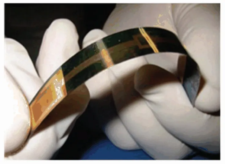
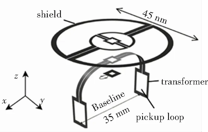
(b)Photograph of the flexible axial gradiometer
Fig.2 Structure diagram and photograph of the flexible axial gradiometer
3 Full Tensor Magnetic Gradient Precision Measurement Technology
Geophysical magnetic survey technology started in the 1940s. Studying the magnetic differences between rocks and ore deposits, it is an effective method to detect underground ferromagnetic ore bodies. Full tensor magnetic gradient measurement simultaneously obtains the gradient values of the three components of the geomagnetic vector in three spatial directions, containing more vector field information. The complete magnetic gradient tensor is a 3 × 3 matrix with 9 components, expressed as
wherex,y, andzdenotes the orthogonal coordinate system.
Because the earth gradient change is much smaller than the magnetic gradient caused by the magnetic anomaly, the tensor gradient measurement has incomparable advantages over the total field and three-component field measurement:
a) It has strong suppression of common mode magnetic field, which can effectively avoid background magnetic field noise;
b) It is not susceptible to the inclination and declination of the geomagnetic field;
c) It is relatively insensitive to orientation, so the requirements for attitude measurement accuracy are not high;
d) The anomalous body can be quickly located by using a limited number of measurement points;
e) Normally, a false magnetic anomaly caused by diurnal variations needs to be eliminated for high-precision magnetic measurement, while full tensor magnetic gradient measurement obviates the need of base stations and corrections for diurnal variations.
Based on the above advantages, full tensor magnetic gradient measurementis not only used in mineral exploration, geological investigation, and other aspects, but also plays a unique role in military applications. Especially in recent years, with the development of submarine stealth technology, traditional submarine detection means, such as radar and sonar, are faced with great challenges. In addition, magnetic gradient tensor measurements are also useful in autonomous navigation and positioning of unmanned aerial vehicles or submarines.
The international tensor gradient system developed by SQUID mainly has three operating modes: ground, air, and underwater. Among them, the aeromagnetic gradient tensor measurement featured with high efficiency exploration develops particularly rapidly.
3.1 Ground Full Tensor Magnetic Gradient Precision Measurement Technology
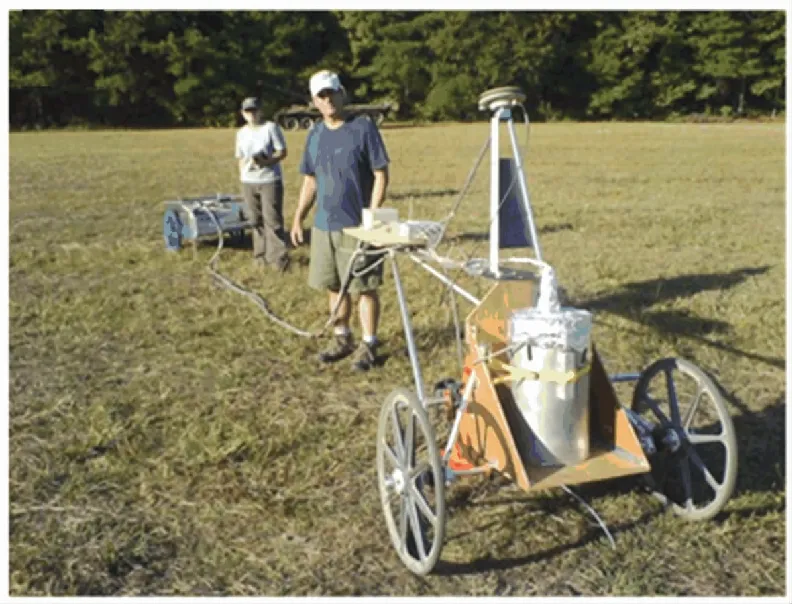
In 2007, IPHT developed a ground full tensor magnetic gradient measurement system carried by a non-metallic cart[8-9]. Sensitive and high balanced LTS SQUID gradiometers form the probe of the system and the system gradient resolution is 700fT/m. The system consists of three sets of subsystems and each one is equipped with one SQUID gradiometer and three reference sensors. It also consists of an inertial navigation system, which provides three attitude data, namely pitch, roll, and yaw, for determining the position of the cart and attitude correction of magnetic measurement data. The system has carried out practical test in an area of about 11 000 m2in Peru and obtained high-precision geographically referenced magnetograms. The results from the measured data are proved to be useful for archaeological excavation.
3.2 Airborne Full Tensor Magnetic Gradient Precision Measurement Technology
IPHT developed JESSY STAR System, which is the most advanced and the only practical airborne full tensor magnetic gradient system in the world. The system utilizes nine LTS SQUIDs housed in the liquid helium Dewar, including six planar gradiometers and three magnetometers. Both fixed wings aircraft and helicopters can carry this system. The differential GPS system and inertial unit provide high spatial resolution and synchronize with magnetic gradient data. The system carried by helicopter was tested in South Africa in 2004 and the first set of airborne full tensor magnetic gradient data in the world was obtained[10]. The area under investigation is about 84 km2, the survey line spacing is 100 m, and the flying altitude above ground is 40 m. At present, IPHT is carrying out aerodynamic optimization on the basis of the original system to develop the second-generation system in order to reduce motion noise interference and further improve the measurement accuracy. In 2019, the newly developed system was used in airborne geomagnetic exploration of three-dimensional magnetization of a dolerite intrusion in central Germany[11]. Two different models were established: one based on magnetic total field and the other based on five tensor components. The residual of the magnetic gradient tensor inversion is between 142 and 317 pT/m (RMS), while the residual of the total magnetic field inversion is 8.9 nT. From the inversion result, it is known that SQUID gradient-based model can decrease the ambiguity in the inversion process and has better consistency with the magnetization and shape of the underground structures.
In 2005,Oak Ridge National Laboratory (ORNL) in the U.S. developed an airborne tensor magnetic gradiometer by combining their geophysical platform with HTS SQUID provided by the U.S. Navy, which is used for unexploded ordnance (UXO) detection and mapping[12]. As shown in Fig.3(b), the system contains eight SQUID sensors in a single package so as to measure five independent gradients. Numerous ground tests were conducted to test the capabilities of the instrument on a moving cart. By analyzing the tensor data obtained from the ground movement test, the equivalent dipole source location can be determined.
(a) Ground movement test
(b) SQUID sensors on the core and structure schematic
Fig.3 High-temperature superconducting tensor magnetic gradient measurement system developed by ORNL
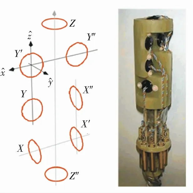
Commonwealth Scientific and Industrial Research Organization (CSIRO) in Australia has always been working on SQUID-based precision geophysical instruments to explore the underground resources. They designed an airborne magnetic gradiometer system GETMAG[13]based on the concept of rotating three axial gradiometers, which are arranged in an umbrella configuration. Swinging the system in 120° increments around the verticalz-axis can measure complete tensor gradient. In May 2007, a series of trials were conducted at Warnervale Airport, Sydney, including driving a truck carrying a known magnetic target past the gradiometer system and flying the gradiometer system over a known target. The measured results matched well with the modelled results[14].
Relevant researches started relatively late in China because China is restricted by the SQUID fabrication technology and SQUID sensors are mainly purchased from abroad. During the 12th and 13th Five-Year Plans, Shanghai Institute of Microsystem and Information Technology (SIMIT) and Chinese Academy of Sciences developed an airborne full tensor magnetic gradiometer prototype by using LTS SQUID. The flight measurement test of the system was carried out in Inner Mongolia and the gradient accuracy reached 30 pT/m. Jilin University developed a full tensor magnetic gradient measurement system prototype using HTS SQUID purchased from CSIRO and carried out the first flight test in Xiong’an, Hebei. The stability of the system during flight was confirmed by experiment. Jilin University proposed a method and circuit for the monitoring and automatic recovery of SQUID’s unlock phenomenon, providing a solution to enhance the reliability of SQUID motion measurement. Two domestic superconducting full tensor magnetic gradient measurement systems are shown in Fig.4.
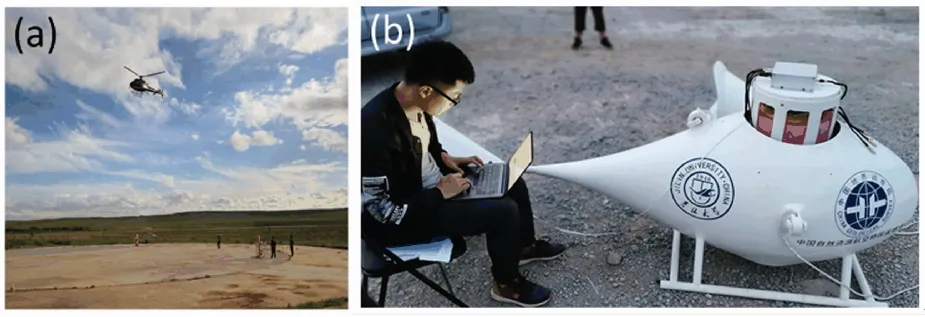
(a) LTS SQUID gradiometer (b) HTS SQUID magnetometer
Fig.4 Domestic superconducting full tensor magnetic gradient systems based on LTS SQUID gradiometer and HTS SQUID magnetometer
3.3 Underwater Full Tensor Magnetic Gradient Precision Measurement Technology
Sonar and infrared underwater detection technologies are vulnerable to interference in complex seawater environments. With the development of submarineair independent propulsion (AIP) technology and noise reduction technology, submarine’s endurance and concealment have been greatly improved, challenging traditional detection methods. In contrast, magnetic detection has the advantages of strong anti-interference ability, high target positioning accuracy, and good concealment of passive detection. Although metal materials and electrical circuits used in ships, submarines, and mines have been demagnetized, the magnetism cannot be completely eliminated. In addition, during long-term exposure to geomagnetic field, they are inevitably re-magnetized, forming a magnetic anomaly source. The underwater full tensor magnetic gradient precision measurement system developed by SQUID can detect the weak underwater magnetic anomaly signal and determine whether there are magnetized targets in the detection area.
Based on the airborne full tensor magnetic gradient system, IPHT developed an underwater system[15]. This system consists of six planar SQUID gradiometers and four SQUID magnetometers, which are installed in a horizontal operating cryostat. The cryostat, a data collector, a helium gas-handling unit, and auxiliary sensors, is mounted inside a pressure tube. As shown in Fig.5, the tube is put in a torpedo-shaped tow body with a length of 4.25 m and a diameter of 0.5 m. A field experiment was performed in September 2016 in the Baltic Sea to test performance in mobile operation[16]. The system worked underwater for 40 hours without trouble. The detection trial of artificial dipole targets was successful, with positioning error of about 10 m and absolute dipole magnetic moment error of about 20%. Compared with IPHT airborne measurement system, this system mainly solves two technical problems: a) The horizontally operating cryostat was developed; b) Pressure of helium gas in the closed tube is maintained and released through a small compressor which keeps balance with outside pressure.
CSIRO designed a full tensor magnetic gradient system based on high-Tc flip-chip SQUID for marine surveying applications[17-18]. As is shown in Fig.6(a), the probe consists of six long baseline planar gradiometers arranged in a hexagonal pyramid configuration. Each face of the pyramid also incorporates a reference SQUID magnetometer to compensate the non-ideal common mode suppression of geomagnetic field. The project is undertaken by a commercial partner, SkyResearch, and it is currently in the laboratory test phase.

Fig.5 Configuration of the underwater system developed by IPHT
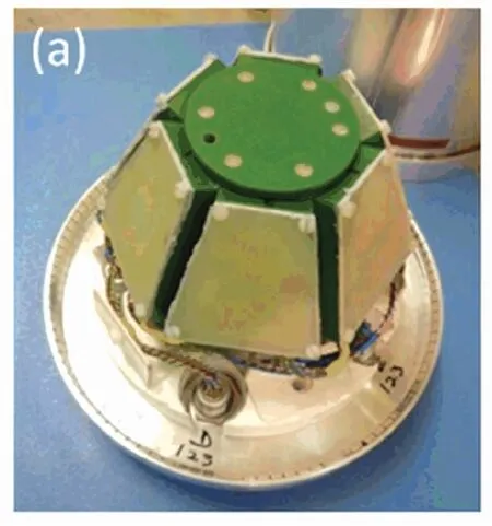
(a) The frame holding the SQUID gradiometers and magnetometers

(b) Ground test
Fig.6 Tensor magnetic gradient system developed by CSIRO
4 SQUID-Based Time Domain Electromagnetic Detection Technology
The transient electromagnetic (TEM) method, also known as time domain electromagnetic method, is a geophysical method to calculate underground resistivity distribution by transmitting periodic pulse currents to the ground, and then observing the time-dependent secondary magnetic field generated by the underground conductor during the interval of transmission. It has advantages of high resolution, simple abnormal response form, and is less affected by the terrain. The secondary magnetic field is mainly derived from the eddy current effect of the underground high-conductivity geological body. Its decay law over time can reflect relevant parameters of geological bodies, such as conductivity, volume scale, and burial depth. The early electromagnetic field in the secondary field signal is equivalent to the high-frequency component in frequency domain, with fast attenuation and low skin depth, while the late one is low-frequency component equivalent, with slow attenuation and large skin depth.
The traditional method uses induction coil to detect the secondary field based on the Faraday law of electromagnetic induction. This method has good detection sensitivity for early signals, but the coil’s detection sensitivity decreases with the decrease of frequency component of TEM signal at late time. As current geophysical exploration depths continue to increase, the limitations of induction coil receivers are becoming more prominent. Using SQUID instead of conventional induction coils in transient electromagnetic method has become a development trend, with the following advantages:
a) Compared with conventional induction coils that detect the time derivative of magnetic field, SQUID directly measures the magnetic field. No integration constant is required, so data inversion becomes easier.
b) SQUID has the advantages in both sensitivity and bandwidth. Its sensitivity of severalfT/Hz1/2is independent of frequency band (DC ~ MHz), so it can obtain better TEM signals in early, middle, especially late period.
c) Magnetic induction intensityBof the secondary field decays with time in the form of e-3/2t, which is slower than the magnetic field change rate measured by the coil.
Thus, SQUID is the idealB-sensor receiver for measuring the secondary magnetic field in TEM, especially the late weak signal containing the information about the deep earth. Another advantage in practical use is that SQUID receiver is more compact and convenient to use. SQUID-TEM is expected to break through the depth detection bottleneck of traditional induction coil TEM method, which has been verified in several laboratories in Australia, Japan, Germany, and other countries. Deep targets, highly conductive targets, or targets under conductive overburden can be more easily detected by SQUID-TEM method.
Fig.7 shows the principle and constituent units of the TEM system utilizing a SQUID magnetometer. The system consists of a current transmitter, a loop coil, SQUID, FLL circuit, and a data collector. The transmitting loop coil generates primary pulse magnetic field to excite the response of the underground ore body. SQUID located at the center of the loop coil measures the secondary magnetic field. Then the SQUID signal is read out by the FLL circuit, and finally sampled and saved by the data collector.
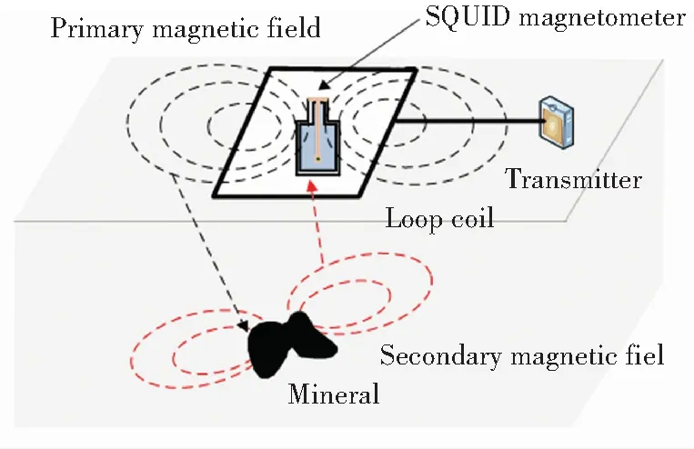
(a) Schematic diagram of the TEM method using SQUID
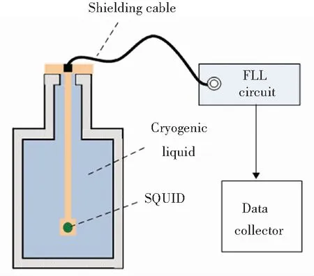
(b) SQUID system
Fig.7 Schematic diagram of the TEM method using SQUID and SQUID system
4.1 SQUID-Based Ground TEM Detection Technology

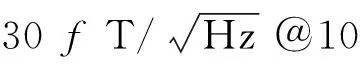
Since 2001, the Japanese Superconducting Sensing Technology Research Association (SUSTERA) has successively developed three generations of HTS SQUID magnetometer system for mineral exploration. The third generation commercial system SQUITEM-3 is shown in Fig.8, which includes a cryostat, a probe, an FLL circuit, and high-speed cables. By utilizing the hybrid-type SQUID sensor with ramp-edge junction made by HTS multi-layer technology and selecting appropriate RF-shielding materials, the tolerance to higher excitation magnetic field was improved[25-27]. The measured white noise and slew rate are respectively 30fT/Hz1/2and 10.5 mT/s. SQUITEM-3 system has been tested in Akita prefecture in Japan, with an interpretation depth of more than 1 000 m[28].
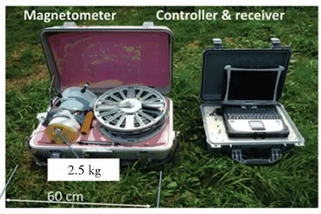
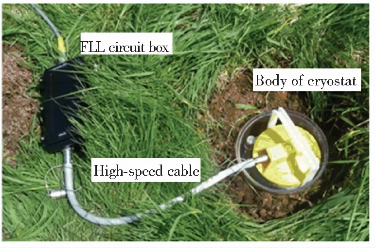
Fig.8 SQUITEM-3 developed by SUSTERA, Japan

(a) SQUID-TEM system

(b) Magnetic source TEM induction-polarization measurement system
Fig.9 SQUID-TEM system and magnetic source TEM induction-polarization measurement system
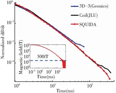
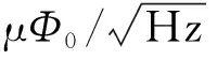
Fig.10 Normalized decay curves measured at the same survey point
4.2 SQUID-Based Airborne TEM Detection
Technology
The airborne SQUID-TEM method is an evolution of the ground system. The transmitting coil and SQUID receiver are carried by an aircraft in the airborne system. Compared with the ground system, it can complete the exploration of a large area with high efficiency while inheriting the high sensitivity of the ground system, speeding up the data collection greatly, and allowing for high data coverage. However, there are few reports on practical airborne systems now. Many practical problems need to be solved in system installation and data processing, including aircraft eddy current field suppression and system remote control.
At the end of last century, CSIRO and Broken Hill Proprietary Billiton Ltd. (BHP) developed the first airborne TEM system based on HTS SQUID[36-37]and the superiority in detecting TEM signals in late period was confirmed by flight experiments. However, the institute later terminated the project and focused on the application of SQUID in ground TEM system. At present, the relatively successful system in the world is the LTS SQUID airborne TEM system developed by IPHT[38]. This system was tested in Thuringia, Germany. Compared with the coil TEM system, SQUID received a TEM signal with a duration of 178 ms, one third of a decade longer than coil recordings. Generally, it had a higher depth of investigation than coil recordings.
4.3 SQUID-Based Well TEM Detection Technology
Compared with large induction coils, SQUID has compact size and can be operated with optical fiber cables from a distance of 3 000 m. Therefore, SQUID is easier to deploy and use in small and complex environments such as drilling and wells.
Based on the above advantages, Japan Oil Gas Metals National Corporation (JOGMEC) developed an induction logging system for oil fields utilizing three orthogonally aligned HTS SQUID sensors[39]. As shown in Fig.11, the SQUID receiver is wrapped in a vessel with high-pressure tightness over 70 MPa and thermal durability of 200 ℃.
(a) Structure of the SQUID receiver and cable
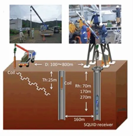
(b) Arrangement of the coil and the receiver
Fig.11 SQUID-TEM well system developed by JOGMEC
SQUID receiver successfully detected the sufficiently large signal for the cases where the depth of the receiver is 270 m and the horizontal distance between the coil and the receiver is 800 m. By inversion analysis of the transient magnetic field signal received by SQUID, the change of resistivity caused by CO2diffusion in oil can be evaluated. JOGMEC is currently developing the new generation of long-distance induction logging SQUID-TEM system, which uses larger magnetic moment transmitting coil and steel-free casing drilling. The expected goal is to increase the distance between the receiver and the coil to more than 1 km.
5 Precise Measurement of Superconducting Gravity and Gravity Gradient
Like the Earth’s magnetic field, gravity is also the basic physical field reflecting the geological structure of the earth. It reflects the fluctuations of the crust, mantle, and its boundaries. Gravity gradient is the second derivative of gravity potential, which has better boundary recognition ability compared with gravity. Gravity and gravity gradient measurement is recognized as the effective means of resource exploration. Gravity instruments have been widely applied in oil exploration, metal exploration, inertial navigation, and other fields.
As the current research hotspot of gravity instruments, superconducting gravity instrument using SQUID is based on the Meissner effect, zero resistance effect, and mechanical stability of superconducting materials at low temperatures. It is far superior with extremely low drift rates, low noise, and constant scale factor, which can provide almost noise-free data for continuous geophysical gravity measurements. Compared with other types of gravity instruments, the superconducting gravity instrument has the following two advantages:
a) The instrument operates in the liquid helium temperature and the thermal noise is very low;
b) The mechanical stability of the material is better and the thermal expansion coefficient of superconducting test-mass (usually niobium,Tc=9.2 K) is only 10-9/K.
There are two types of superconducting gravity instruments:superconducting gravimeter (SG) and superconducting gravity gradiometer (SGG). SG is mainly used for station observation, while SGG has its unique advantages in ship-borne and airborne platform for mobile measurement.
5.1 Superconducting Gravimeter
Currently, SG is the most precise instrument to study gravity variations both in time and frequency domain. Traditional mechanical spring-type gravimeter can also record continuous gravity. However, temperature and pressure-induced instrument effects and changes in scale factors can reduce data quality in long-term measurement. It takes effort to calibrate the instrument before it is used. In essence, the superconducting gravity instrument still belongs to the spring type gravimeter, while the mechanical spring is just replaced by the superconducting magnetic levitation spring. The superconducting spring works under ultra-low temperature environment, which has perfect stability.
The working principle of SG is shown in Fig.12. Because of the zero resistance of superconductor at superconducting transition temperature, persistent currents can be stored in the supercurrent coil. Under the magnetic field caused by current, the surface of superconducting test-mass will generate a canceling magnetic field. The test-mass levitates at a balanced position because of its own gravity and magnetic force. The position of the superconducting test-mass and the effective inductance of the coil change correspondingly with the gravity. According to the loop magnetic flux conservation, the effective inductance will change the supercurrent in the coil. This supercurrent is transmitted through superconducting mutual inductance coil to the circuit where SQUID input coil is located and is finally detected. So the superconducting circuits incorporating SQUID as well as the inductive element close to test-masse are used to detect the displacement of test-mass.
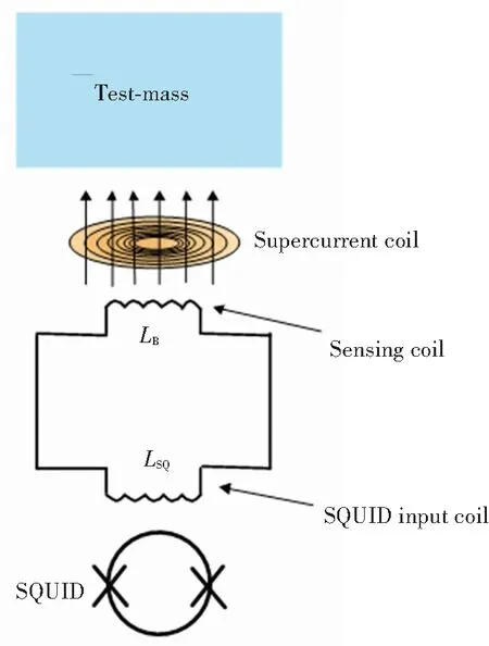
Fig.12 Principle of the superconducting

5.2 Superconducting Gravity Gradiometer
Since the torsion balance gravity gradiometer invented by the Hungarian geophysicist Eotovs in 1890, the gravity gradiometer has been continuously developed, including rotary gravimeters from Hughes, liquid floating gravimeters from Draper, and rotary accelerometers gravimeters from Bell. All of them have made important contributions to geophysical exploration. Rotary accelerometers gravimeter emerged in the 1990s and quickly gained great success in commercial exploration. At present, it is still the most accurate gravity gradiometer in the world[41]. With the demand for greater depth of resource exploration, the next-generation gravity gradiometer based on superconducting technology have attracted the attention of geophysical instrument developers. It has the advantages of low noise, high sensitivity, good mechanical stability, and wide dynamic range, which has promoted the new development of gravity gradient instrument.
The basic working principle of SGG is consistent with the gravity measurement. A single-axis gravity gradiometer is composed of two identical superconducting accelerometers mounted on a rigid platform separated by a certain distance along a baseline. The measured gravity gradient is equal to the difference between the two accelerometers divided by the baseline length.
The Paik team at Stanford University built the world’s first SGG and the team later moved to the Physics Department at the Maryland University. After a continuous development over more than three decades, in 2011, the Maryland University designed a three-axis cross-component gravity gradiometer for moving operation[42-43], with RMS noise of 0.53 E in the bandwidth of 0.001 to 1 Hz. It contains six identical angular accelerometers and three identical translational accelerometers. Six identical angular accelerometers are installed on the surfaces of a precision cube and translational accelerometers are installed on three orthogonal surfaces. Opposing pairs of angular accelerometers are coupled together with superconducting circuits to measure cross components of the gravitational gradient.
Currently,advanced SGG include the EGG system from ARKeX, UK, the VK-1 system jointly developed by the University of Western Australia and Rio Tinto, and the HD-AGGTM system from GEDEX Canada. However, no research institute has developed an airborne superconducting gravity gradiometer with the performance equivalent to that of rotary accelerometer gravity gradiometer.
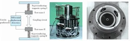
(a) Principle of Γzz single-axis superconducting (b) Sensitive probe (c) Superconducting accelerometer
gravity gradiometer
Fig.13PrototypeofSGGdevelopedbyHuazhongUniversityofScienceandTechnology
6 Conclusions and Outlook
SQUID has a prominent advantage in the field of geophysical precision measurement, including full tensor magnetic gradient measurement, time domain electromagnetic method, superconducting gravity, and gravity gradient measurement. Research institutes around the world have made a series of technological breakthroughs on SQUID-based geophysical precision measurement technology, but are also faced with many challenges. The main directions for future development are as follows:
1)SQUID, as a high-performance magnetic sensor, is widely used in the vector measurement of the geomagnetic field. The full tensor magnetic gradient measurement system for the ground, aviation, wells, etc. has fully demonstrated the advantages of SQUID. However, in the mobile state, especially in aeronautical applications, SQUID is easy to exceed the slew rate, which makes SQUID electronics unable to work properly. At present, only IPHT has a practical airborne full tensor magnetic gradient system. Compared with the airborne system, the underwater system is more difficult to develop. However, driven by the demand for marine mineral resources detection, the application research of SQUID in this field is an important development direction.
2)SQUID has obvious advantages in ground TEM applications, and there are many successful cases. This is mainly due to its high magnetic measurement sensitivity and satisfactory low frequency performance, while it avoids the problems existing in SQUID movement measurement at the same time. Therefore, compared with the induction coil, it can detect the longer TEM secondary field signal, effectively improving the detection depth. However, when SQUID is applied to airborne TEM, the same problems exist as in the full tensor magnetic gradient mobile system. Therefore, it is necessary to make breakthroughs in key technologies for similar problems. Drilling and wells SQUID-TEM is a new subject developed in recent years, and it is a noteworthy development direction in SQUID-TEM research.
3)SQUID has the advantages of high micro-displacement detection accuracy, good stability, and high sensitivity in the measurement of gravity and gravity gradient, and plays an irreplaceable role in high-resolution relative gravity measurement instruments. However, if it is transplanted to the mobile platform, such as airborne gravity and gravity gradient measurement, it still needs to solve many technical difficulties such as motion platform matching, cross-coupling noise suppression, etc. There is still a long way to go before it is practical.
In conclusion, SQUID-based geophysical precision measurement technology has outstanding advantages but is faced with many challenges. Therefore, it is necessary to explore new application points of SQUID and carry out original research work. On the other hand, we must meet the major national application needs and make technological breakthroughs through multidisciplinary crossover and innovative design, so that SQUID can play an important role in solving practical major problems in the field of geophysics.
Acknowledgments
Some original drawings quoted in the paper about the working principle, structure, and performance of the instrument come from the reports and articles of CSIRO, SUSTERA, SIMIT, Huazhong University of Science and Technology, Jilin University, etc. The authors admire and respect their wisdom and dedication in SQUID and SQUID-based geophysical precision measurement technology.
杂志排行

Journal of Harbin Institute of Technology(New Series)的其它文章
- Review: Recent Progress on the Application of REBCO Superconductor Bulks
- Review: Recent Development of High-Order-Spectral Method Combined with Computational Fluid Dynamics Method for Wave-Structure Interactions
- Effects of Rapid Cooling Rate on Microstructure Formation and Microhardness of Binary Ti-44Al Alloy
- Effects of Fiber Surface Pretreatment and Composite Post- treatment on Mechanical Properties of 2D-Cf/Phosphate Geopolymer Matrix Composites