Numerical simulations on cutting of frozen soil using HJC Model
2020-07-01WenQiangZhangYongHongNiu
WenQiang Zhang ,YongHong Niu
1.State Key Laboratory of Frozen Soil Engineering,Northwest Institute of Eco-Environment and Resources,Chinese Academy of Sciences,Lanzhou,Gansu 730000,China
2.University of Chinese Academy of Sciences,Beijing 100049,China
ABSTRACT Numerical simulation is known as an effective method for mechanical properties during frozen soil excavation.In order to reveal the development of cutting force,effective stress and cutting fragments in frozen silt during the cutting process,we introduce an explicit finite element program LS-DYNA to establish a two-dimensional numerical model of the frozen soil cut.We also use the Holmquist-Johnson-Cook(HJC)damage constitutive model for simulating the variation of soil me‐chanical properties according to the strong dependence between the cutting tool and frozen silt during the process with dif‐ferent cutting depths,angles and velocities.Meanwhile,a series of experimental results are acquired of frozen silt cutting to prove the application of the HJC model during simulation of cutting force variations.The result shows that the cutting force and fragment size are strongly influenced by cutting depths and cutting velocities increased,and the maximum effec‐tive stress at points where the tool contacts frozen soil during the cutting process.In addition,when the cutting angle is 52°,the cutting force is the smallest,and the cutting angle is optimum.Thus,the prediction of frozen soil mechanical prop‐erties on the cutting process by this model is conducive to selecting machinery equipment in the field.
Keywords:frozen soil cutting;numerical simulation;HJC damage constitutive model;mechanical properties
1 Introduction
Frozen soil is a heterogeneous and anisotropic multiphase complex composed of solid particles,ice inclusions,liquid water and gas(water vapour and air).The main difference between frozen soil and un‐frozen soil is whether ice exists or not(Tsytovich,1985;Andersland and Ladanyi,2004).The excava‐tion of frozen soil will be involved in the construction of a series of major projects in cold regions.Reducing the wear and prolonging the working life of frozen soil excavation equipment,and improving the excava‐tion efficiency become increasingly important for con‐struction projects in cold regions(Liu et al.,1996).The essence of the excavation process of frozen soil is the interaction between frozen soil excavation equip‐ment and frozen soil.Therefore,the study of this inter‐action in the excavation process of frozen soil is bene‐ficial to optimize the frozen soil excavation equip‐ment,improve the excavation process of frozen soil and raise the excavation efficiency of frozen soil(Lu and Huo,1988).
Numerous studies have been conducted on the in‐teraction between cutting tools and frozen soil,such as frozen soil cutting tests,and the variations of cut‐ting force with temperature,moisture content,cutting depth,cutting speed and cutting angle(Burton and Ukrainetz,1977;Phukan and Takasugi,1982;Tsytovi‐ch,1985;Yu et al.,1991;Zhang and Yu,1994).How‐ever,the cutting test of frozen soil is usually expen‐sive and time-consuming,and it is usually completed in a laboratory under low speeds and shallow cutting conditions,which is different from actual high speeds cutting and deep cutting conditions in the field.It is also difficult to directly observe the fragment separa‐tion process and effective stress change during the cut‐ting process of frozen soil.Using a numerical simula‐tion method to study the interaction of frozen soil cut‐ting process can not only obtain variations of cutting force with parameters,but also directly observe the process of cutting damage of frozen soil.This not on‐ly produces great economic value,but also provides help for theoretical and experimental research.Nu‐merical simulation is widely used to study the interac‐tion between rock and cutting tool in the rock cutting process.For example,Kou et al.(1999)used the twodimensional plane strain Rock Failure Process Analy‐sis(RFPA)method to simulate the process of rock cut‐ting.This model qualitatively predicted the consider‐able damage of the cutting tool during the cutting pro‐cess,and predicted development of various shaped chips in front of the cutting tool,but the separation process of chips were not predicted.Cho et al.(2010,2013)studied the process of rock fragmentation using explicit finite element program AUTODYN-3D.In these simulations,the volume of cut rock is deter‐mined by using the erosion options provided in the fi‐nite element program,and rock elements reaching the level of tensile failure in the simulation process are deleted immediately.Menezes et al.(2014a,2014b,2016)used an explicit finite element program LS-DY‐NA,selected the model*MAT_DAMAGE_2,estab‐lished a two-dimensional rock cutting model,studied the influence of different cutting parameters on rock cutting mechanical behaviour, and analyzed the change of effective stress in the rock cutting process.Zhang et al.(2016)used the explicit finite element program LS-DYNA to simulate the dynamic mechani‐cal behaviour of frozen soil under impact load.How‐ever,the physical and mechanical properties of frozen soil are complex.At present,there is no suitable dy‐namic frozen soil constitutive model for numerical simulation of cutting process of frozen soil,and re‐search on numerical simulation of cutting process of frozen soil is scarce.The aforementioned research provides a certain reference for numerical simulation of cutting process of frozen soil.
Considering the higher cost and data limitation of laboratory test of frozen soil cutting,the numerical simulation of rock cutting provides a trusted method as seen in this study.Based on rational simplifications and assumptions,we use the finite element program method to simulate the cutting process of frozen soil under −8°C.By building a two-dimensional simula‐tion model of cutting process of frozen soil, we choose the HJC damage constitutive model of simula‐tions to further research conditions of larger cutting depths,cutting angle and higher cutting velocities.It should be noted that variations of cutting force,effec‐tive stress and fragment morphology in the cutting process of frozen soil should always be obtained.We expected to find the mesoscopic physical characteris‐tic of frozen soil cutting in the mechanical properties and effective stress changes in the interaction between cutting tools and frozen soil.
2 HJC damage constitutive model and twodimensional finite element model of frozen soil cutting
LS-DYNA is a general explicit non-linear dynam‐ic analysis program with strong applicability;it can solve various two-dimensional and three-dimensional non-linear dynamic impact problems,such as explo‐sion,metal forming,cutting and high-speed collision(Hao and Hu,2010).The HJC model involved in LSDYNA is originally suitable for simulating dynamic impact mechanical behaviour of brittle materials such as concrete.In cold regions,the soil is commonly sub‐jected to a negative temperature that can remarkably change the physical properties.During freezing,soil mechanical properties typically became higher strength which involves the water phase changing into ice and cementation between particles.Therefore,the HJC model in LS-DYNA program was used to simu‐late the cutting process of frozen soil which is consid‐ered as a constitutive model.
2.1 HJC damage constitutive model
The HJC damage constitutive model is used to simulate damage and failure behaviour of brittle mate‐rials such as frozen soil under large strain,high strain rate and high pressure.The normalized equivalent stress is defined as(Holmquist et al.,1993):
where σ∗is normalized equivalent stress,σ is actual equivalent stress,and f'cis quasi-static uni‐axial compressive strengthen;is the nor‐malized hydrostatic force;the non-dimensional strain rateis a ratio of the true strain rateand reference strain rateA,B,N and C are normalized cohesive strength, normalized pressure hardening, pressure hardening exponent and strain rate coefficient,respec‐tively;and D is the damage factor and is determined by the accumulation of the equivalent plastic and plas‐tic volumetric strain:

where Δεpand Δμpare the equivalent plastic strain and plastic volumetric strain for one calculation cycle,respectively;andare the equivalent plastic strain and the plastic volume strain for crushing at atmo‐spheric pressure,respectively.
P is the actual hydrostatic pressure and can be de‐termined by the state equation of curve presented in Figure 1.
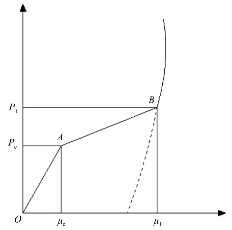
Figure 1 Relation between hydrostatic pressure and volume strain in HJC model
The first stage is the linear elastic stage(OA sec‐tion).The relationship between hydrostatic pressure and volumetric strain is linear as follows:

where K is the elasticity bulk modulus.
The second stage is the compression deformation stage(AB section),the pore in frozen soil is gradually compressed to produce plastic deformation.Here:

where K'is the plastic bulk modulus.
The third stage is complete compaction stage(BC section),in which the internal pore of frozen soil is completely compacted and is in the stage of complete destruction.Here:

where K1,K2and K3are material constants,andis the modified volumetric strain.
2.2 Two-dimensional finite element model of frozen soil cutting
The cutting process of frozen soil is a very com‐plicated thermo-solid coupling process.In the cut‐ting process of frozen soil,the interaction between tool and frozen soil will have a friction heat genera‐tion effect,which will affect the cutting force,and tool wear is always accompanied in the cutting pro‐cess.The tool wear,cutting force and cutting friction heat will affect each other,but in this two-dimension‐al numerical study of frozen soil cutting,the process of interaction between tool and frozen soil is reason‐ably simplified,and the following assumptions are made:
(1)The numerical simulation is a plane strain problem.
(2)The frictional heat generation between cutting tool and frozen soil is not considered in the cutting process of frozen soil.
(3)The cutting tool is defined as a rigid body,re‐gardless of the deformation caused by tool impact and the wear caused by friction in the cutting process of frozen soil.
(4)The cutting tool keeps uniform motion in the cutting process.
(5)In this numerical calculation,the failure units are deleted immediately.
Considered the short time of a frozen soil cutting test or frozen soil excavation,this paper uses the userdefined unit system cm-g-us for numerical simulation,that is,the unit of length is cm,the unit of mass is g,and the unit of time is μs.The calculated value can be used after conversion.
The two-dimensional finite element model of fro‐zen soil rotational cutting is presented in Figure 2.The finite element model is divided into frozen soil model and cutting tool model. The left figure ABCDEF is a frozen soil model with a geometric di‐mension of 6cm×20cm.The EF is an arc with an an‐gle of 60°,representing pre-cutting before formal cut‐ting,which can simulate the actual cutting state more truly.The right tool is composed of a rotating shaft and a cutting tool.The geometric size of the rotating shaft is 2.00cm×5.29cm.The cutting tool size var‐ies with the cutting angle.M is the rotating axis point assumed by the tool in the finite element model,that is,the bottom edge center of the rotating shaft.The*MAT_RIGID was selected to the cutting tool,the main parameters are presented in Table 1.The mesh is divided into 200 parts in length and 400 parts in width by the mapping method,and the mesh of cut‐ter is sparse.
In this numerical simulation, the displacement boundary conditions were as follows:
(1)The Z direction of frozen soil was constrained.
(2)The X,Y and Z directions of left nodes of fro‐zen soil(AB)were constrained.
(3)All translation and X,Y direction rotation of cutting tools were constrained.

Table 1 Selection of tool parameters
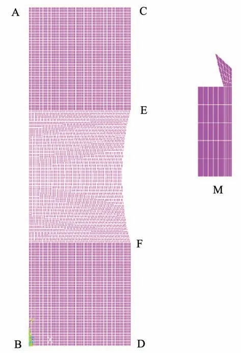
Figure 2 Model of 2-D rotary cutting for frozen soil
2.3 Selection of model parameters
The frozen soil presents different physical and me‐chanical properties under different negative tempera‐ture and moisture content conditions.This numerical simulation only considered frozen silt at −8°C.When the HJC damage model was directly applied to frozen soil,it had some limitations;the most important prob‐lem was the selection of model parameters.Therefore,under the assumption of basic parameters,it is neces‐sary to carry out corresponding simulation tests to de‐termine the important impact parameters,i.e.,parame‐ter calibration.
The HJC damage model includes 21 parameters.The basic parameters included density ρ0, shear modulus G,Poisson's ratio v,uniaxial compressive strengthand uniaxial tensile strength T,all of which were obtained through experiments,as present‐ed in Table 2.The sample density is 2,050 kg/m3,dy‐namic elastic modulus E is 2,100 MPa,uniaxial com‐pressive strengthis 8 MPa(He et al.,1993;Xu et al.,1998;Luo et al.,2013),Poisson's ratio v is 0.35(Xu et al.,1998),and the uniaxial tensile strength T is 0.8 MPa(Shen et al.,1995;Zhu et al.,1995;Ma,1996;Peng,1998).According to the formula G=E/2(1+2v),the shear modulus G is 778 MPa.The crush‐ing volume force Pcis based on the formula2.67 MPa,and the crushing volume strain μcis based on the formula μc=Pc/E=0.0013.Compaction pres‐sure Plis 300 MPa,volume strain μlis 0.15,minimum fracture plastic strain Ɛfminis 0.06,and reference strain rateis 1E−6.
Numerous simulation experiments are needed to determine the parameters of A,B,N,C,K1,K2,K3and fsinvolved in the model(Li et al.,2009).Through the simulation experiments of frozen silt,it was found that changes of parameters N,C,K1,K2and K3have a weak influence on simulation results,and changes of parameters A,B and fshave a significant impact on the cutting force of frozen silt.Thus,this paper will focus on the values of these three parameters.
Fixing the other parameters,and only parameter A was changed,the variations of cutting force in frozen soil is presented in Figure 3.It can be seen that with the increase of parameter A,the cutting force of fro‐zen soil increased rapidly at A<1,while after A>1,the increasing velocity of cutting force of frozen soil gradually slows down.
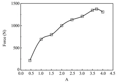
Figure 3 Effect of parameter A on cutting force of frozen soil
Figure 4 shows the variation of cutting force of frozen soil by changing B value while other parame‐ters remain fixed.From Figure 4,it can be noted that the cutting force of frozen soil increased with parame‐ter B increasing,and the cutting force of frozen soil was decreased significantly when parameter B is larg‐er than 1.5.
Different from previous studies,the variation of parameter fsin a certain range has a significant impact on simulation results in the process of frozen silt cut‐ting.Previous studies have shown that parameter fshave little effect on simulation results,and the general value is 0.01(Wu et al.,2010).Figure 5 shows the in‐fluence of different parameters fson the cutting force of frozen soil.From this figure,it can be seen that when parameters fswas between 0.01 and 0.5,the cut‐ting force of frozen silt was changed significantly.When the value of fsis greater than 0.5,the cutting force of frozen soil basically tended to a stable state.
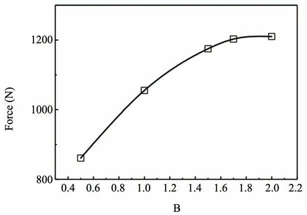
Figure 4 Effect of parameter B on cutting force of frozen soil
Through several simulation calculations of param‐eters A,B and fs,it was found that the cutting force of frozen soil can be significantly changed.Parameters A,B and fsare 2.5,1.5 and 0.5,respectively,to ensure that the cutting force of frozen soil is within a reason‐able range.In conclusion,parameters of the damage model of HJC adopted in this paper are presented in Table 2.
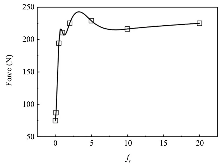
Figure 5 Effect of parameter fs on cutting force of frozen soil
3 Results and discussion
3.1 Influence of cutting depths
Figure 6 shows the variations of effective stress distributions of frozen soil during the cutting process with different cutting depths(d=6,9,12,15,18 mm)at cutting angle of 58°and cutting velocity of 1.4 m/s.In this figure,it can be seen that the maximum effec‐tive stress of inner frozen soil under different cutting depths is mainly distributed at the part where the tool contacts the frozen soil during the cutting process,and the effective stress of frozen soil along with the distance increasing from the edge decreased.For ex‐ample,when the cutting depth is 6 mm,the maximum effective stress at the part where the cutting tool is in contact with the frozen soil is 6.39 MPa,and distant from the edge the effective stress decreased to 0 MPa.In addition,the effective stress value inside the frozen soil under different cutting depths is rather different.When the cutting depth is 9 mm,the value of effective stress of the contact part of frozen soil is 7.23 MPa.Meanwhile,the value of effective stress increased to 9.43 MPa by increasing the cutting depth to 18 mm(presented as Figure 7).Also,at the beginning of cut‐ting,fragments begin to form and separate from the frozen soil along the edge of the tool as the cutting progresses,moreover,cutting depths are shallow and the size of the frozen soil fragments is small.Whenev‐er the cutting depths increased,the size of the frozen soil fragments became larger.
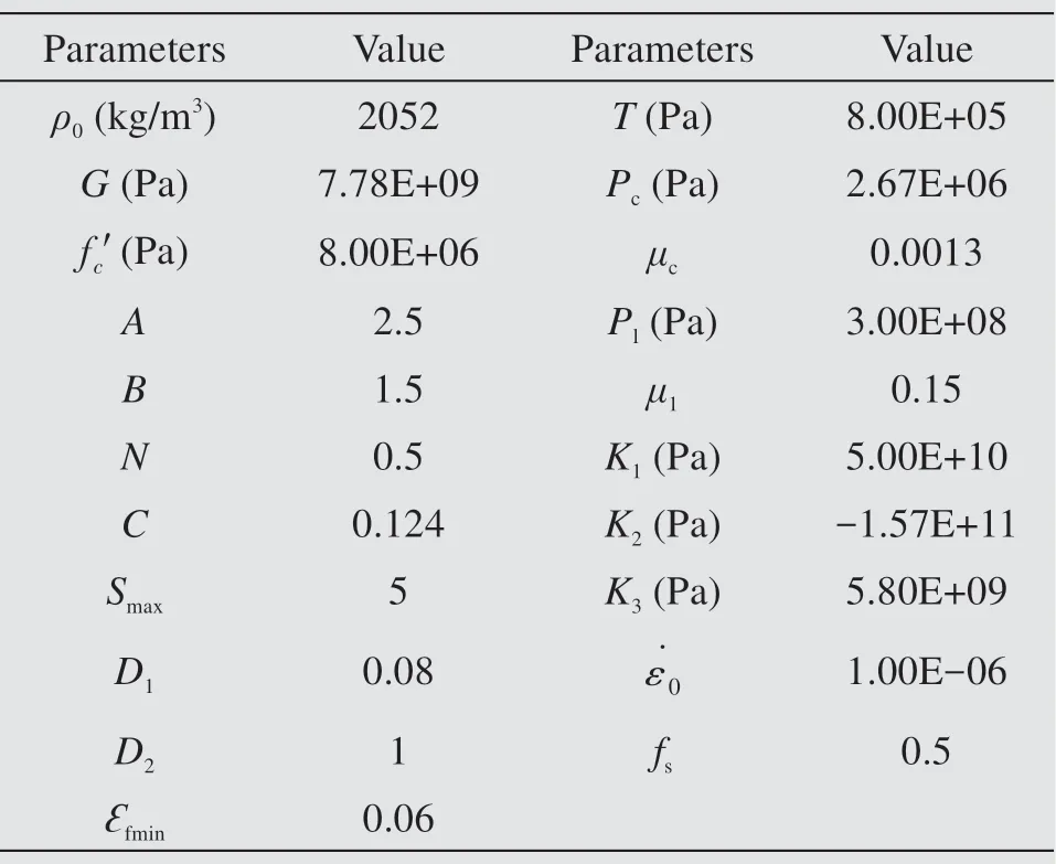
Table 2 Selection of HJC Model parameters
When constructing the realistic model of frozen soil cutting,the effect of force at the tool edge needs to be properly accounted for.There is consumed ex‐cessive energy when the cutting depth is too shallow.However,when the cutting depth is too large,the stress and strain of the tool will increase significant‐ly,leading to the tool breaking.Therefore,to more clearly illustrate the relationship between cutting depths of frozen soil and the cutting force of the tool,we simulated the variation of cutting force un‐der different cutting depths(d=6,9,12,15,18 mm)with four cutting angles,presented as Figure 8.The cutting force in this figure appears as a linear rela‐tionship with increasing cutting depths.For 48°,the cutting force is 923.88 N at a 6 mm cutting depth,and reaches a maximum value at a 18 mm cutting depth of the soil.Such a phenomenon indicates that with the tool progressing in the frozen soil,the cutting tool shifts downward,resulting in larger cutting force.This behavior is attributed to the restraining influence of the fixed vertical end boundary which induces ac‐tion that results in larger stresses.When the cutting depth is increased,the fixed vertical end boundary be‐came lager,and the cutting tools must overcome cohe‐sion and friction between frozen soils,leading to a larger cutting force.On the other hand,in the finite el‐ement simulation,the units were destroyed more dur‐ing the cutting process as the depth increased.Com‐pared with other cutting experimental results of fro‐zen soil(Phukan and Takasugi,1982),a similar ten‐dency is very common.
3.2 Influence of cut angles
Figure 9 shows the variations of the effective stress of frozen soil at different cut angles(α=48°,52°,55°,58°)for a cutting depth of 15 mm and cut‐ting velocity of 1.4 m/s.It is pertinent to observe that simulation results demonstrate the two zones depict‐ed in an ideal finite element presented in Figure 8.In the area above the cutting plane,very little deforma‐tion is experienced.On the other hand,the region be‐low the cutting plane,the soil is moved down from the original position. This motion indicates that stress distribution occurred throughout this zone.This figure show that a certain amount of damage oc‐curs between the blade surface and the adjacent soil.Especially for 52°,the internal maximum effective stress of frozen soil changed significantly,and the ef‐fective stress at the parts where the tool contacts the frozen soil reached a minimum value of 8.38 MPa(presented as Figure 10).In addition,from the fig‐ure,one can see that the morphology of the frozen soil fragment has not basically changed with differ‐ent cutting angles.
Cutting simulations were also performed using frozen soil at different angles(α=48°,52°,55°,58°),five depths of cutting and cutting velocity of 1.4 m/s under identical operating conditions(present‐ed as Figure 11).Figure 11 demonstrates that the cut‐ting force firstly decreased and then increased with in‐creasing cut angles,and for the cut angle of 52°,there was a minimum value for cutting force under differ‐ent cutting depths.Considering cut angles increas‐ing,the friction between the frozen soil fragment and the front blade surface of the cutting tool was re‐duced,while the contact area between the tool and the frozen soil became larger leading cutting force in‐creased.Also,the friction between the rear blade sur‐face and the frozen soil increased,causing a mini‐mum value at the cut angle of 52°.Based on previ‐ous experimental results(Yu et al.,1991;Zhang and Yu,1994),the present simulated results were some‐what different;the optimum cut angle was a fixed val‐ue that did not change with different cutting depths and cutting angles.
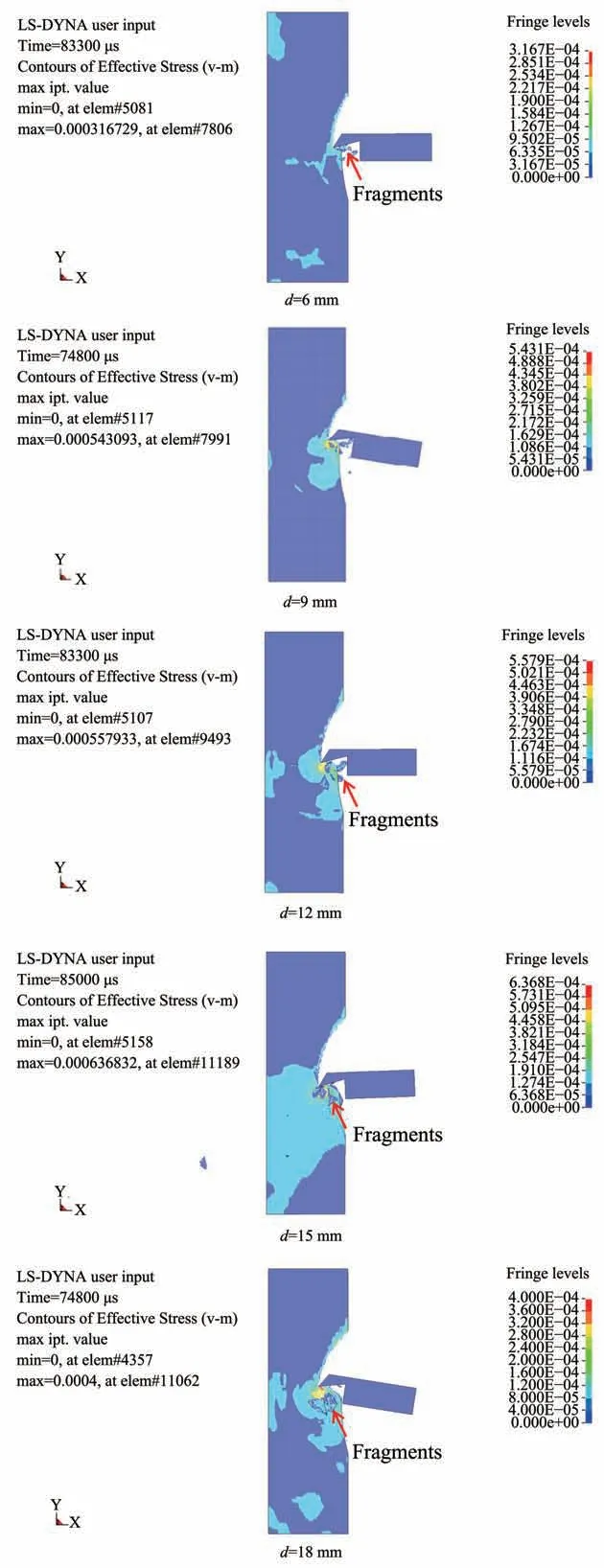
Figure 6 Evolution diagram of effective stress in frozen soil under different cutting depths
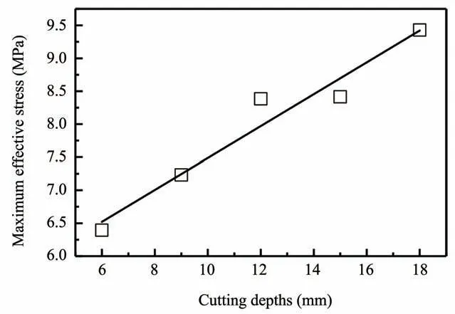
Figure 7 Maximum effective stress vs.cutting depths
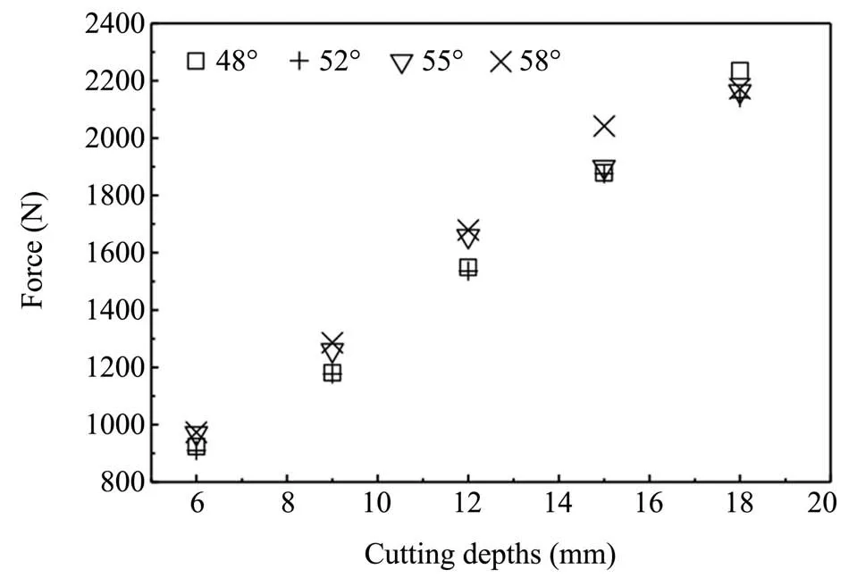
Figure 8 The curve of cutting force of frozen soil with cutting depths
3.3 Influence of cutting velocities
Figure 12 shows the variations of effective stress and fragment size for various velocities(v=1,1.4,1.8,2.2.2.6,3.0 m/s)under cutting angle of 48°and cutting depth of 18 mm.A series of models were analyzed with various cutting velocities using HJC models.It should be noted that increasing for‐ward velocities led to an increase in internal maxi‐mum effective stress at the parts where the tool con‐tacts the frozen soil during the cutting process.For example,the maximum effective stress in contact part is 8.31 MPa when the forward velocity is 1 m/s,while forward velocity of 3 m/s is 9.86 MPa.Re‐sults show the significant effect of cutting veloci‐ties on cutting effective stress of frozen soil.Mean‐while,comparing Figure 12 it also can be conclud‐ed that the size of frozen soil fragments depend on cutting velocities,more specifically,the size of fro‐zen soil fragments increased when the cutting veloc‐ity increased.
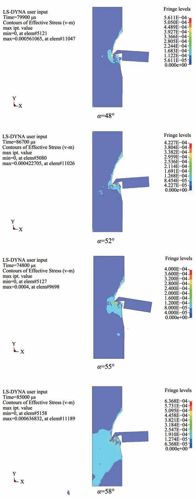
Figure 9 Evolution diagram of effective stress in frozen soil under different cutting angles
In previous research,the effect of the cutting force under different cutting velocities of the frozen soil during cutting process also be investigated.It should be noted that the cutting velocity has little effect on cutting force,only at higher cutting veloci‐ties present a significant effect on cutting force(Yu et al.,1991;Zhang and Yu,1994).However,in this study,the cutting velocity plays an important role in variation of the cutting force,as presented in Fig‐ure 13.This figure presents the cutting force ob‐tained in the frozen silt for four cutting angles(α=48°,52°,55°,58°)at the cutting depth of 18 mm with different cutting velocities shown as Figure 13.It can be seen that the cutting force mainly in‐creased with increasing cutting velocity for differ‐ent cutting angles.When the cutting velocity was 2.2 m/s,the cutting force was reduced,noted to be the critical velocity. Such observations were not found for the other four velocities.In addition,com‐paring different cutting angles,the cutting force for the cutting angle of 52°is minimal at different cut‐ting velocities.As the influence of cutting angle,the cutting angle of 52°was an optimal cutting angle.
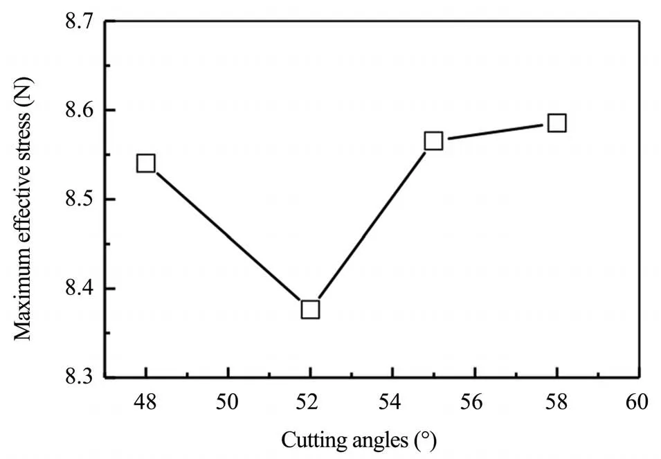
Figure 10 Maximum effective stress vs.cutting angles
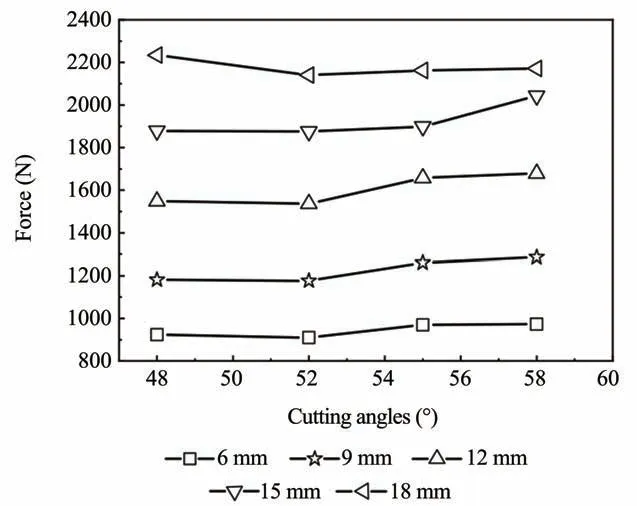
Figure 11 The curve of cutting force of frozen soil with cutting angles

Figure 12 Evolution diagram of effective stress in frozen soil under different cutting velocities
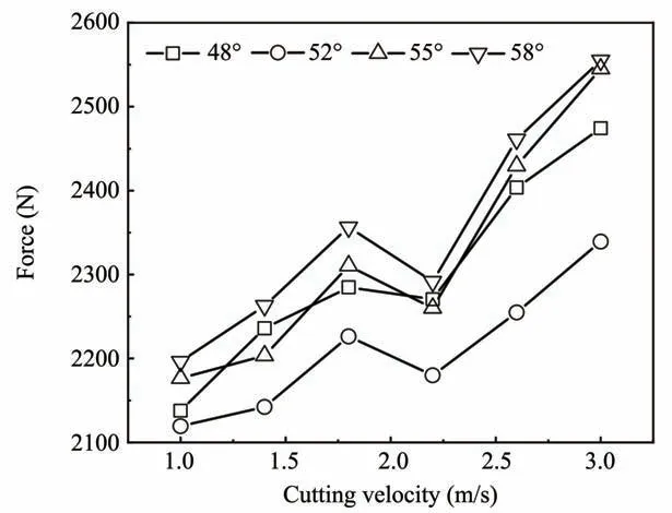
Figure 13 The curve of cutting force of frozen soil with cutting velocities
3.4 Discussion
The aforementioned simulation results demon‐strate that the effective stress peak for the frozen soil occurred at the edge of the tool,and it decreased when the distance from the tool increased.This phe‐nomenon agrees well with experimental results.The wear of the cutting tool is an important factor to influ‐ence the results of the numerical simulation during the cutting process,while in the numerical model,the tool is considered as rigid and tool deformation is ne‐glected.Thus,it is necessary to consider the tool as an elastoplastic material in future research.
Based on numerical simulation results,the cutting force of frozen soil increased linearly with cutting depths and increasing velocities.Meanwhile,the cut‐ting angle had a significant effect on cutting forces for a given velocity and depth of cut.It was observed that among the four cutting angles,the cutting force was lowest for the cutting angle of 52°.General trends were found that the cutting angle of 52°was an opti‐mal cutting angle.It would be a significant effect on cutting force when considering the friction heat gener‐ation during the cutting process of frozen soil.Howev‐er,in this study,friction heat generation between fro‐zen soil and cutting tool is neglected.Mainly because in a real situation,the friction between frozen soil and cutting tool has little effect on the temperature of fro‐zen soil,and the strength of frozen soil decreased with increasing temperature,and is also beneficial to the ex‐cavation process of frozen soil.For further research,to observe changes of cutting forces more clearly,friction heat generation should be considered during numerical simulations.Therefore,the cutting layer temperature and the strength of frozen soil would be obtained to analyze the changes of cutting force.In addition,the interaction between different frozen soils and tool ma‐terials caused different effect on cutting forces,which will also be considered in further research.
In order to provide a reference on optimizing fro‐zen soil cutting machinery equipment,choosing the cutting method,and improving the efficiency of fro‐zen soil cutting,we also need to study the influence of the width and arrangement of the tool during the cut‐ting process in further research.
4 Conclusions
This paper demonstrated the use of the finite ele‐ment program LS-DYNA,and used the HJC model to simulate the cutting process of frozen soil.It was ob‐served that in the frozen soil cutting process the most influential parameters are cutting depths,cutting an‐gles,and cutting velocities.Also,the change of effec‐tive stress and the morphology of fragments during cutting process under different conditions are de‐scribed.The main conclusions based on the numerical simulations are drawn as follows:
(1)We used an explicit finite element program LSDYNA and HJC damage constitutive mode to simu‐late the variation of mechanical properties of frozen soil during the cutting process.Excellent simulation results between the cutting tool and frozen soil during the cutting process provides information for selecting equipment in the field.
(2)The variations of cutting force with different cutting depths,cutting angles,and cutting velocities during the cutting process can be simulated,respec‐tively.The mechanical behavior of frozen soil under higher cut depths and cutting velocities were verified,especially at the 18 mm cutting depth of soil where the cutting force reaches the maximum value.More‐over,compared with different angles,the angle of 52°can be concluded as an optimal cutting angle.
(3)Based on the numerical simulation,the maxi‐mum effective stress was located at the parts where the tool contacts the frozen soil during the cutting pro‐cess.Also,the effective stress decreased with the dis‐tance from the contact part increased.In addition,the influence of cutting depth and cutting velocity on frag‐ment shape during the cutting process of frozen soil is significant,while the cutting angle did not strongly ef‐fect the formation of fragments.
Acknowledgments:
This research was financially supported by the Natu‐ral Key Research and Development Program of China(Grant No.2017YFC0405103).
杂志排行
Sciences in Cold and Arid Regions的其它文章
- A modified numerical model for moisture-salt transport in unsaturated sandy soil under evaporation
- Editors-in-Chief Yuanming Lai and Ximing Cai
- Mapping the dynamic degree of aeolian desertification in the Shiyang River Basin from 1975 to 2010
- Quantitatively estimate the components of natural runoff and identify the impacting factors in a snow-fed river basin of China
- A meta-analysis of the impacts of forest logging on soil CO2 efflux
- Fast genetic mapping in barley:case studies of cuticle mutants using RNA-sequencing
