Vickers hardness change of the Chinese low-activation ferritic/martensitic steel CLF-1 irradiated with high-energy heavy ions
2020-06-14ZhaonanDING丁兆楠ChonghongZHANG张崇宏YitaoYANG杨义涛YuguangCHEN陈宇光XianlongZHANG张宪龙YinSONG宋银TongdaMA马通达YupingXU徐玉平andGuangnanLUO罗广南
Zhaonan DING (丁兆楠),Chonghong ZHANG (张崇宏),Yitao YANG (杨义涛),Yuguang CHEN (陈宇光),Xianlong ZHANG (张宪龙),Yin SONG (宋银),Tongda MA (马通达),Yuping XU (徐玉平) and Guangnan LUO (罗广南)
1 Institute of Modern Physics,Chinese Academy of Sciences,Lanzhou 730000,People’s Republic of China
2 School of Nuclear Science and Technology,University of Chinese Academy of Sciences,Beijing 100049,People’s Republic of China
3 General Research Institute for Nonferrous Metals,Beijing 100088,People’s Republic of China
4 Institute of Plasma Physics,Chinese Academy of Sciences,Hefei 230031,People’s Republic of China
Abstract
Keywords:CLF-1,RAFM steel,heavy ions,irradiation,hardening
1.Introduction
Irradiation by the high-energy neutrons from the D–T reaction in fusion reactors will produce defects and gaseous impurities including helium in structural components such as the first wall/blankets,resulting in embrittlement and swelling of materials,thereby seriously restricting integrity and safety in long-life operation of fusion reactors.Due to excellent thermophysical and mechanical properties,good resistance to void swelling as well as low-activation,reduced-activation ferritic/martensitic (RAFM) steels have been considered as prime candidates for structural materials for fusion reactorblankets [1,2].The Chinese RAFM steel CLF-1 is one such candidate material for the design and manufacture of the helium-cooled ceramic breeder test blanket module (HCCB TBM) [3].Previous studies have shown that the ductile–brittle transition temperature and high-temperature tensile properties,especially the tensile strength of CLF-1,are close to the international level for the same type of RAFM steel,but there is still a lack of research on its response to irradiation.In view of the fact that hardening /embrittlement under irradiation is a crucial issue for the use of RAFM steels in the low-temperature regime (below 400°C),more studies are needed to clarify the performance of CLF-1 under irradiation.
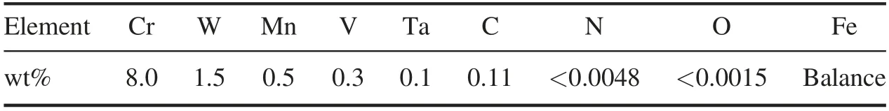
Table 1.Specific chemical composition of CLF-1 steel in wt%.
The Vickers micro-hardness is known to have a direct correlation with the yield strength of steels.Busby et al [4]found that there is a simple interrelation between yield stress and Vickers hardness for austenite and ferrite steel after neutron irradiation.The Vickers hardness test does not require a large volume of material[5].The hardness and depth profile information obtained from the irradiated surface can be further analyzed to establish the correlation between the Vickers hardness and the macroscopic mechanical properties of the material [6].For a reliable evaluation of the irradiation hardening of steels by the Vickers micro-hardness test,the region damaged by irradiation needs to be thick enough so as to readily minimize the contribution of the unaffected substrate of the specimens.Besides various neutron sources,ion beams generated by high-energy accelerators are also applicable as surrogates [7]due to some attractive attributes such as higher damage rates,easier control of irradiation parameters and lower radioactivity of samples,enabling easy handling for the post-irradiation examination.Moreover,cascade damage induced by energetic heavy ions in materials is similar to that by fast neutrons [7].Therefore,heavy ions can be used to simulate neutron irradiation of structural components [8–10].
In the present work,specimens of CLF-1 steel were irradiated with high-energy heavy ions to successively increasing damage levels at a low temperature where irradiation-induced hardening is significant.Vickers hardness together with nano-hardness were tested.Correlation between the Vickers micro-hardness and the nano-hardness and the dependence of the observed hardening on the irradiation dose were investigated.Finally,irradiation hardening data from other RAFM steels were compiled and compared.
2.Experimental
The material used in the present study was a Chinese RAFM steel CLF-1.The chemical composition of CLF-1 is listed in table 1.Details about the manufacturing process for CLF-1 have been described in previous papers [3,11–13].Before irradiation,a block of CLF-1 was sliced into specimens of 1 cm × 1 cm with a thickness of about 1 mm and mechanically ground with SiC abrasive paper (from grades 800 to 2400) then carefully polished with diamond suspensions(~1 μm)to obtain smooth surfaces.The final thickness of the sample was about 200 μm.
The irradiation experiment was carried out at a terminal chamber of the Sector-focused Cyclotron at the Heavy Ion Research Facility in Lanzhou located in the Institute of Modern Physics of the Chinese Academy of Sciences.The chamber was equipped with a beam intensity monitoring assembly,an energy degrader and a liquid nitrogen-cooled specimen stage.The beam current was monitored with a Au foil assembly placed in the beam line before the energy degrader,consisting of a 1 μm thick Au foil to collect electric charge,a circular aperture of diameter 15 mm to limit the irradiation area and a circular aperture of diameter 18 mm with a bias voltage of-300 V to suppress secondary electron emission.At the beginning and the end of the irradiation,the beam current monitoring assembly was calibrated using a Faraday cup mounted at the end of the chamber.The incident mono-energetic heavy ions were dispersed into 11 different energies by an energy degrader in front of the specimen stage,which includes a rotatable wheel consisting of several aluminum foils of different thicknesses.During irradiation the thickness of the aluminum foil varies as the wheel rotates at a speed of 12 rpm,dispersing the incident ions with different energies and thus producing a nearly uniform distribution of displacement damage in the specimens.Further details about irradiation terminals are given in our previous paper [14].
In the present study,14N and56Fe ions with kinetic energies of 63 MeV and 336 MeV,respectively,and a beam flux of around 5 × 10¹⁰ions cm–2s–1were used.Three successively increasing damage levels [0.05,0.1 and 0.2 displacements per atom (dpa)]were applied.The lowest and intermediate damage levels were due to N ion irradiation at a damage rate of about 0.01 dpa h-1.While the highest dose(0.2 dpa)was from Fe ion irradiation at a damage rate of about 0.02 dpa h-1.Depth profiles of atomic displacement damage (in dpa) in the CLF-1 specimens,irradiated with N ions to the lowest dose and Fe ions to the highest dose,are shown in figure 1,according to an estimation using the SRIM-2013 code (quick calculation,displacement threshold energy Ed=40 eV) [15].The dpa is obtained as the average displacement damage of the superposed value located at damage peak of multi-energy irradiation.The specimens were mounted on a stage cooled with liquid nitrogen so that the effects of beam heating are efficiently suppressed.A thermocouple was mounted on the sample stage to monitor the temperature during irradiation.The position of the specimen stage is adjustable,enabling a switch from one specimen to another.During irradiation,the temperature of the specimen stage was stabilized at about -50°C.Numerical analysis shows that beam heating causes the specimen temperature to be about 20°C higher than that of the specimen stage during irradiation.The vacuum of the sample chamber is around 2.5 × 10⁻⁵Pa.
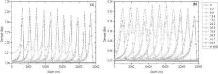
Figure 1.Depth profiles of the displacement damage in CLF-1 specimens according to SRIM-2013 simulation,corresponding to a dose level of(a)0.05 dpa by N ions and(b)0.2 dpa by Fe ions.The dashed red line shows the superposed effect.A series of different Al foil thicknesses(in micrometers) of the energy degrader is shown in the right column.
After irradiation,the samples were preserved in the chamber in a rough vacuum at room temperature for 172 and 105 days corresponding to N and Fe irradiation,respectively,so as to take the radioactivity down to the background level.Then they were used for the nano-indentation test and Vickers hardness test.
Testing the nano-hardness with the nano-indentation technique was described in our previous paper [16].The soft substrate effect,which is usually observed in low-energy ion irradiation experiments,was not seen in the present work.The broad quasi-uniform damage plateau from near the surface to about 25 μm (figure 1) facilitates direct measurement of the Vickers hardness.In the present study,a Vickers hardness tester (Wilson T2500,Buehler Ltd.,USA) was used.A standard sample was used for calibration before the test.Eight different loads (98 mN,196 mN,490 mN,980 mN,1.96 N,4.9 N,9.8 N and 19.6 N)were applied to the sample surface for 10 s each to measure the Vickers hardness of each specimen.The corresponding indentation depth varied in the range from 1.2 to 18.6 μm.For each load three indentation points were randomly selected on the specimen surface with a minimum distance of 200 μm,and the average value was taken.The Vickers hardness tests were conducted at room temperature.
3.Results and discussion
3.1.Irradiation hardening
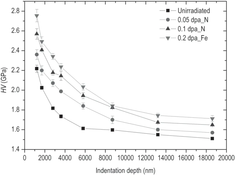
Figure 2.Average Vickers hardness versus indentation depth of CLF-1 specimens under different conditions.
Figure 2 shows typical indentation depth profiles of the average Vickers hardness of three indents under each load for CLF-1 before and after irradiation.It can be seen that the measured hardness of all the specimens decreases with increasing indentation depth,known as the indentation size effect (ISE) [17].Moreover,hardening is observable in the irradiated specimens and increases with increase in the damage level.In figure 3,the extent of irradiation hardening at different doses is depicted by the hardness ratio of irradiated and unirradiated specimens.It can be seen that the ratio has a peak value at an indentation depth of about 3.8 μm.At this indentation depth,the hardening percentage is about 14%,23% and 28% for damage levels of 0.05,0.1 and 0.2 dpa,respectively.The ratio decreases monotonically at deeper indentation depths.
Nix and Gao[18]developed a model based on geometrically necessary dislocation to explain the ISE,in which the hardness as a function of depth is given by the following equation:
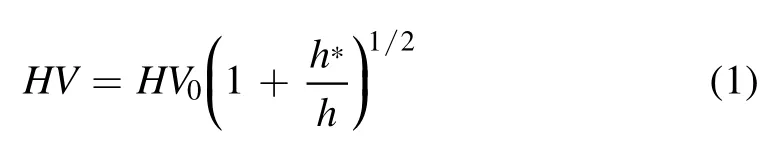
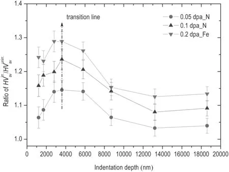
Figure 3.Ratio of/ versus indentation depth corresp-onding to different doses.
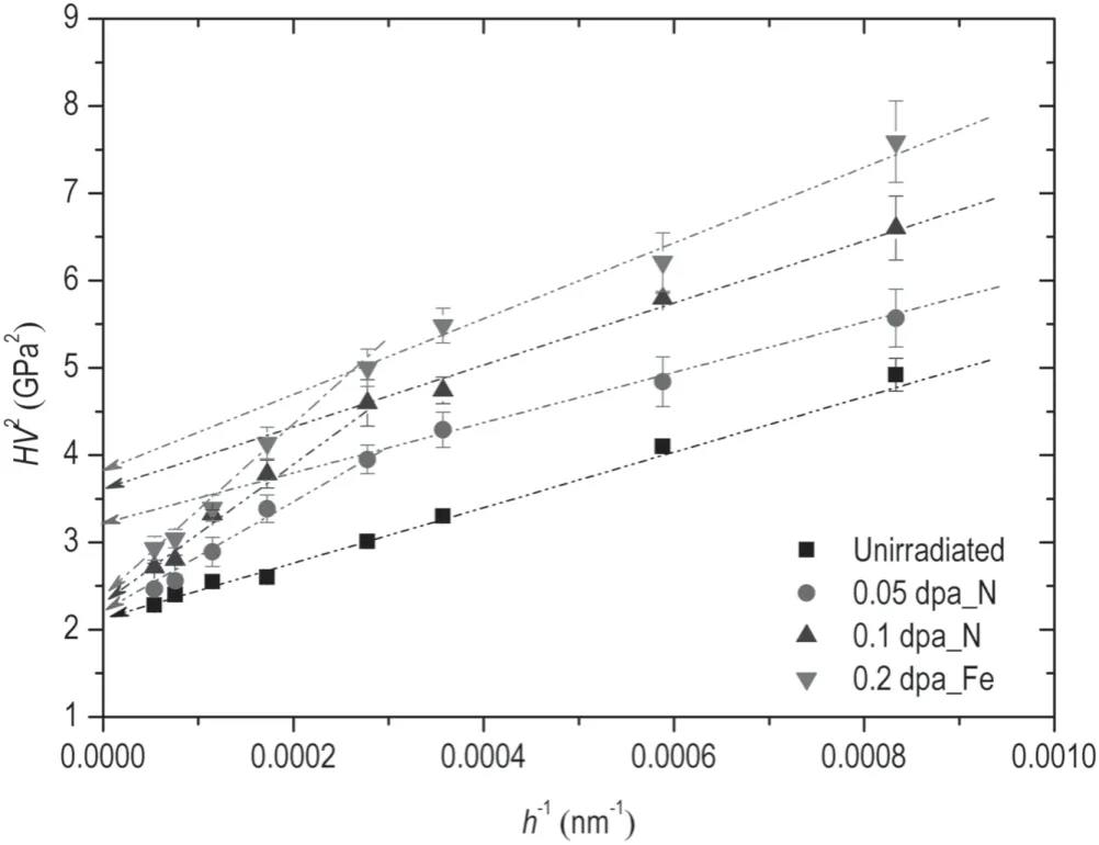
Figure 4.Plots of HV2 versus 1/h for the average Vickers hardness of unirradiated and irradiated CLF-1 specimens.
where HV is the measured hardness of the material,HV0is the hardness at infinite depth(i.e.bulk equivalent hardness),h is the indentation depth and h*is a characteristic length that depends on the material and shape of the indenter.It can be found from the equation that the square of the hardness varies inversely with the indentation depth.
For further analysis,the hardness data versus indentation depth in figure 2 were replotted accordingly as HV2against 1/h,as shown in figure 4.Plots for the unirradiated specimen show a good linearity in the overall indentation depth range.However,plots for the specimens irradiated with heavy ions exhibit a distinct bilinearity,with an inflection point at a depth of around 3.6 μm,which coincides with the depth of the maximum ratio in figure 3.In the test,eight different loads(i.e.98 mN,196 mN,490 mN,980 mN,1.96 N,4.9 N,9.8 N and 19.6 N) were used,corresponding to indentation depths ranging from 1.2 μm to 18.6 μm.Since the zone affected by elastic deformation is generally a few times broader than the indentation depth,the undamaged substrate starts to contribute to the hardness test when the indentation depth exceeds the inflection point [19,20].From figure 2,the indentation depth of the initial five loads (i.e.98 mN,196 mN,490 mN,980 mN,1.96 N) was about 1.2 μm,1.7 μm,2.8 μm,3.6 μm and 5.8 μm,respectively.The corresponding elastic deformation zones below the indenter are generally about four to seven times deeper than the indentation depth.The elastic deformation zones of the initial four loads should be within the damaged layer (which is 25 μm thick) of the irradiated specimens,while that of the fifth load(1.96 N) should exceed the boundary of the damaged layer.Under larger loads the unirradiated soft substrates make a greater contribution to the hardness test,causing a different depth dependence of the hardness data [21].
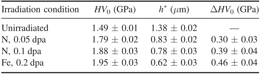
Table 2.HV0 and h* for CLF-1 steel calculated by the Nix–Gao model.Data are averages from three indents under each load.
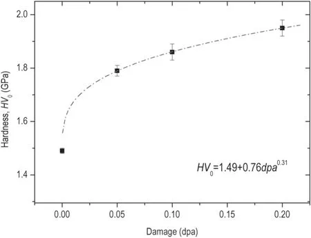
Figure 5.Bulk equivalent hardness HV0 as a function of damage level for CLF-1 steel.
The bulk equivalent hardness HV0can therefore be obtained by extrapolating from the least-squares fitting of hardness data in the range of 1.2 μm < h < 3.6 μm for the irradiated specimens,according to equation (1).Values of HV0and h*are given in table 2.
The dependence of HV0on the irradiation damage level(dpa) is plotted in figure 5.Fitting of the data suggests a power-law relationship:

where the unit of HV0in the equation is GPa.The hardness initially increases quickly with dose (<0.05 dpa) and then slows down further with doses up to 0.2 dpa,showing a hardening saturation trend.
The Vickers micro-hardness data are further compared with the nano-hardness obtained previously by nano-indentation tests from the same CLF-1 specimens [16].As shown in figure 6,the Vickers micro-hardness data reveal a linear relationship with nano-hardness,which can be described by the following equation:
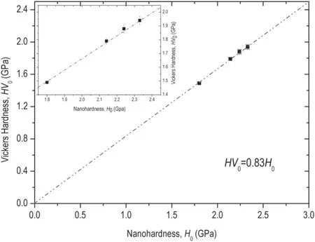
Figure 6.The Vickers hardness(HV0)as a function of nano-hardness(H0) for unirradiated and irradiated CLF-1 specimens.
A similar linear relationship was found for various steels in our previous work[22,23]and also by Yabuuchi et al[10].The projection contact area is used in the analysis of nanoindentation data,while the residual projection area is used in Vickers hardness analysis [9].Therefore,the coefficient is only related to the geometric size of the indenter and hardness unit when Vickers hardness and nano-hardness are defined in the same way.
In order to compare the irradiation hardening with other RAFM steels,data on the increase in yield strength were compiled from previous neutron and ion irradiation experiments.Based on the relationship between Vickers hardness and yield stress [4],data on the increase in Vickers hardness of CLF-1 in the present work and those of CLAM in[24]are converted to increase in yield stress by the following equations [8]:
where Δσyis the increase in the yield stress in units of MPa,ΔHv is the increase in Vickers hardness in units of kgf mm-2and ΔHV is the the increase in Vickers hardness in units of GPa.Equation (5) shows the relationship between ΔHv and ΔHV.
The results are shown in figure 7,together with data from the tensile tests of other RAFM steels irradiated with fast neutrons or protons reported in[25–27].Despite the variety of irradiation sources and the minor difference in the compositions/manufacturing routes of the RAFM steels,the increase in yield strength versus the level of irradiation damage generally follows a similar power-law function.The dose dependence of the increase in yield strength of CLF-1 steel in the present work shows a similar power exponent to the data for RAFM steels,including neutron- or proton-irradiated modified JLF-1,F82H and Optimax A.The temperature and dose rate have a minor effect on the irradiation hardening of RAFM steels,possibly because at temperatures below 300°C the mobility of the major defect species (interstitial-type clusters,vacancies) is limited and does not significantly alter the microstructures caused by primitive cascade damage.
The power exponent in the case of the neutron-irradiated Eurofer97 is significantly higher than for other RAFM steels.The difference in the power exponents of the dose dependence is mainly due to the microstructures of the RAFM steels before irradiation.A further comparison of the microstructures prior to irradiation,including the density of dislocations and precipitates and grain-boundary structures,should be helpful for understanding the differences in dose dependence of irradiation hardening between the RAFM steels.
4.Conclusions
The irradiation hardening behavior of CLF-1 steel irradiated by high-energy heavy ions to successively increasing damage levels (i.e.0.05,0.1 and 0.2 dpa) was studied.The broad thickness of the damaged layer (about 25 μm) facilitates the direct measurement of Vickers hardness.The depth distribution of Vickers hardness was obtained by applying eight different loads on the specimens with a hardness tester.The Vickers hardness data were analyzed by the Nix–Gao model and the bulk equivalent hardness values corresponding to different conditions were obtained.The bulk equivalent hardness HV0is linearly related to the previous nano-indentation test results by HV0=0.83H0.Hardening is observable at the lowest damage level,and increases with increasing irradiation dose.A power-law dependence of the irradiation damage level,HV0=1.49 + 0.76 dpa0.31,was observed.A comparison with other RAFM steels under neutron or charged particle irradiation conditions shows that most RAFM steels show similar power-law exponents in the dose dependence of irradiation hardening.The differences in irradiation hardening may be attributed to difference in microstructure prior to irradiation,which requires further investigations.
Acknowledgments
This work was sponsored by the National Magnetic Confinement Fusion Program(No.2011GB108003)and National Natural Science Foundation of China (No.U1532262).We are grateful for the experimental conditions provided by the Heavy Ion Research Facility in Lanzhou (HIRFL).
ORCID iDs
猜你喜欢
杂志排行

Plasma Science and Technology的其它文章
- Comparison of discharge characteristics and methylene blue degradation through a direct-current excited plasma jet with air and oxygen used as working gases
- Evaluation of influence of cold atmospheric pressure argon plasma operating parameters on degradation of aqueous solution of Reactive Blue 198 (RB-198)
- Plasma-induced graft polymerization on the surface of aramid fabrics with improved omniphobicity and washing durability
- Plasma-assisted abatement of SF6 in a packed bed plasma reactor:understanding the effect of gas composition
- The far-field plasma characterization in a 600W Hall thruster plume by laser-induced fluorescence
- Experimental study of a low-pressure hybrid RF discharge