Overview of Satellite Laser Ranging for BeiDou Navigation Satellite System
2020-03-09ZHANGHaifengLONGMingliangYANGHuafengMENGWendongCHENGZhienDENGHuarongZHANGZhongpingZHANGli
ZHANG Haifeng ,LONG Mingliang ,YANG Huafeng ,MENG Wendong ,CHENG Zhi'en ,DENG HuarongZHANG Zhongping,ZHANG A'li
1 Shanghai Astronomical Observatory,CAS,Shanghai 200030 2 Key Laboratory of Space Object and Debris Observation,CAS,Nanjing 210008 3 Beijing Satellite Navigation Center,Beijing 100094 4 Xinjiang Astronomical Observatory,CAS,Urumqi 830011
Abstract:Satellite laser ranging (SLR) is an unambiguous measurement technique and generates high accuracy satellite orbit data.All satellites in the BeiDou navigation satellite system (BDS) carried laser retro-reflector arrays (LRAs),so they can be tracked by ground SLR stations in order to provide the accurate observation data.The Shanghai astronomical observatory (SHAO) designed the LRAs,and also developed the dedicated SLR systems using a 1 m-aperture telescope and a transportable cabin-based SLR system with a telescopes of 60 cm aperture.These enable BDS satellite ranging during daytime and nighttime with centimeter-level precision,allowing highly accurate estimations of satellite orbits.Moreover,some of the BDS satellites are also equipped with laser time transfer (LTT) payloads,which were developed by the SHAO and China Academy of Space Technology (CAST),providing a highly accurate time comparison between the satellites and ground clocks.This paper describes the dedicated SLR system and the design of the LRAs for BDS satellites,as well as global SLR measurements.The SLR tracking data is used for evaluating the orbit accuracy of BDS satellites and broadcast ephemeris,with an accuracy of less than 1 m.The LTT measurements to BDS satellites for a single shot have a precision of approximately 300 picoseconds,with a time stability of 20 picoseconds in 500 s.
Key words:BDS satellites,satellite laser ranging,laser retro-reflector array,global SLR tracking,laser time transfer
1 INTRODUCTION
Satellite laser ranging (SLR) is used to determine the distance to a satellite from the ground station by measuring the time-of-flight of the laser.Using the SLR's technique to obtain the precise orbit determination of a dedicated set of passive laser-ranged satellites,it provides a direct method of testing and verifying the relative distance[1].The post-fit root-mean-square(RMS) residuals for orbit determination (OD) were respectively 8.81 cm and 12.00 cm using 49 normal points (NPs) and 47 NPs for the Quasi-Zenith Satellite 1 (QZS-1) and a Chinese geostationary-orbit satellite BDS-2 G1,respectively[2].The SLR technique is an unambiguous satellite measurement technique capable of night/day operation proving near real-time global data availability.Hence,the technique is widely used in precise orbit determination,determination of the rotation parameters of the Earth,establishment and maintenance of a global Earth reference framework and high-precision laser time measurement worldwide.The global SLR stations,making up the International Laser Ranging Service (ILRS) global tracking network,are in different shapes and sizes,and were built by different institutions at different times using different technologies[3].For the Global Navigation Satellite Systems (GNSS),the precise measurement of satellite orbit is indispensable,so high-accuracy SLR techniques for achieving high-precision navigation and positioning services were used[4].SLR measurements for GNSS satellites are a valuable parameter to validate GNSS orbit modeling techniques.Precise GNSS orbit determination can be achieved using SLR data only or in combination with microwave data[5-6].
The BeiDou Navigation Satellite System (BDS) is a GNSS domestically developed by China,providing high-quality position,navigation and time services for global users[7].The BDS constellation includes three kinds of satellite orbits including Geosynchronous Earth Orbit (GEO),Inclined Geosynchronous Satellite Orbit (IGSO) and Medium Earth Orbit (MEO) where the orbital altitude is 36,000 km for the IGSO,GEO,and 21,500 km for the MEO,different to other navigation satellite systems.Like the GPS,GLONASS and Galileo system[4-6],the BDS satellites also carry laser retro-reflector arrays (LRAs) and adopt the technology of SLR,thus enabling laser ranging accuracy to the centimetre-level or even sub-centimetre level,which plays a significant role in the independent validation of precise orbits[7].
As BDS uses GEO,IGSO and MEO satellites,the orbit determination strategies are different from other GNSS and a high-precision measuring technique independent from satellite orbits is needed.Shanghai Astronomical Observatory (SHAO)has been developing the technology for SLR for several decades[8].It is the coordinator of the Chinese SLR network,and also started to design LRAs from 1999.To date many sets of LRAs for different Earth orbiting satellites have been manufactured and launched[9].In order to determine the precise orbits and conduct precise measurements for the BDS satellites,SHAO has been designing and manufacturing the LRAs and the dedicated SLR system for laser ranging for the BDS satellites since 2006.Up to now,more than 30 BDS satellites with LRAs have been launched into orbit[10].A dedicated SLR system with a 1 m-aperture telescope and a cabin-based SLR system with a 60 cm aperture telescope have also been developed for laser ranging to BDS satellites.For acquiring the global coverage SLR data used for the orbit determination and orbit evaluation,a subset of BDS satellites are tracked regularly via the global SLR system coordinated by the International ILRS and to date this subset exceeds more than 30 global navigation satellites in the tracking priority list of ILRS[11].In addition,it is very important for the GNSS system in evaluating the performance of satellite clocks and so the Laser Time Transfer (LTT) was first proposed and applied in BDS by the SHAO[12].
In the sections that follow,we describe two sets of dedicated SLR systems to range BDS satellites and the characteristics of LRAs of with BDS satellites.The global laser tracking for BDS satellites was performed in order to determine orbit and the evaluation of broadcast ephemeris.The last section presents the LTT measurements with a SLR system using a telescope of 1 m aperture,along with the future development plans for China's LTT technology.
2 THE DEVELOPMENT OF A DEDICATED SLR SYSTEM
2.1 Dedicated SLR System with a Telescope of 1 m Aperture
The dedicated SLR system was developed by the SHAO with a telescope of 1 m aperture for laser tracking to BDS satellites from 2008 to 2012[13].The main specifications of the system were as follows:
Aperture of receiving telescope:1000 mm.
Aperture of transmitting telescope:300 mm.
Laser system:150 mJ@532 nm,250 ps pulse width,20 Hz.
Tracking and pointing performances of telescope:the precision is at arc-sec level.
As SLR technology developed,the SLR system was upgraded with a 1 kHz repetition rate laser and SLR controller.Figure 1 shows the 1 kHz repetition rate laser ranging to GEO satellites during daytime,and the red points are laser echoes,amongst noise data.The measuring precision is better than 2 cm at night time and in daytime.
2.2 The Transportable Cabin-based SLR System

Figure 1 The laser ranging to BDS GEO satellites in daytime
With the development of the global BDS system,evolving from the regional BDS-2 system to the global BDS-3 system,more and more BDS satellites were launched into space and the constellation was completed at mid-year 2020.The original SLR stations in China could not meet the requirements for tracking all the BDS satellites.Hence,the Chinese SLR network was upgraded to meet the need for the new BDS satellites by SHAO in 2017,with the introduction of a transportable cabin-based SLR system,enabling laser ranging in daytime and nighttime for the DBS MEO,IGSO and GEO satellites.This SLR system can be transported on a trailer from one site to another.It has the advantage of multi-site laser ranging to BDS satellites.The other calibration requirement that might to be required with the transportable SLR is for a co-located microwave calibration system.
The structure of the transportable cabin-based SLR system is built based on a container where the top and sides of cabin were designed to be operable.The cabin was separated into a telescope room,a laser room and a control room,as shown in Figure 2.
The heavy-duty fixtures are mounted in a removable case,the top of the container is flat.The container roof can be opened to enable measurement for the low-altitude BDS satellites,while the design provides protection against rain,wind and dust.It is equipped with a workbench,and an air conditioner.The main specifications of the transportable SLR system are as follows:
Aperture of receiving telescope:600 mm.
Aperture of transmitting telescope:100 mm.

Figure 2 The transportable cabin-based SLR system
Laser system:1.6 mJ@532 nm,45 ps pulse width,1000 Hz repetition rate.
In addition to the measuring devices in the fixed SLR system,the specific designs considered:1) three legs to support the telescope mount;2) four shock absorbers installed on the cabin to guard against vibration;3) near target,for system delay calibration,was installed on the telescope to meet the transportation requirements.The transportable cabin-based SLR system was completed in 2020 and provides laser ranging data for the BDS satellites in daytime. Figure 3 shows the laser ranging to the BDS IGSO 3 in daytime with a measurement precision of better than 2 cm.

Figure 3 The laser range to the satellites BDS IGSO 3 in daytime
3 CHARACTERISTICS OF THE BDS LRA
The LRAs installed on the Earth facing side of the BDS satellites are the key component for SLR measurements.Generally,dozens of cube corners are integrated into LRAs,so they can increase the effective reflective area to reflect as many laser photons back as possible[14].Therefore,the performance of LRAs has a significant impact on the ability to reflect laser photons and hence the measuring precision for BDS satellites.
3.1 LRA Design
When a cube corner prism is tilted,the angle between the normal to the pupil entrance and the incident wavefront normal isi,so the effective areaA(i) is:

where,μis,iis angle of incidence,i'is refracted angle of incidence,andnis index of refraction of prism.
For the flat reflective plate of LRAs,the average cross section of cube corner array can be expressed[15]:

The incident angle between the laser pulse and the pupil entrance of LRAs can be calculated from the following formula:.

where,Redenotes the radius of the Earth;Hsdenotes the orbit altitude of the satellite;eldenotes the elevation of the satellite.When the BDS satellites are respectively located at an elevation of above 20°,the maximum incident angleiis less than 13°.For the un-coated fused silica cube corner,there exists a critical angle of total reflection,which allows for light reflection when the incident angle is smaller than 16°.In this case,the type of common planar LRAs used for the BDS satellites can meet the requirement of laser total reflection[16].The specifications of LRAs developed for MEO and GEO/IGSO satellites are shown in Table 1.
In order to compensate the velocity aberration(max.5.2" for the MEO satellites and max.4.2" forthe GEO/IGSO satellites),the dihedral angle offset of a corner cube was set to 0.6 arc-seconds and 0.5 arc-seconds for the MEO and GEO/IGSO satellites respectively,the surface of the corner cube was un-coated and the reflectivity rate at a wavelength of 532 nm was more than 92%.

Table 1 LRAs Specifications for MEO and GEO/IGSO satellites
3.2 The Structural Design of LRAs
Each corner cube in the LRAs was installed into an independent chamber,with a small gap surrounded each corner cube to ensure no damage due to fused silica material expansion and contraction.Each chamber component was fixed into a plane base hexagon array,which was formed an approximate circular shape to reduce the return laser pulse spread thus achieving better ranging precision.The shapes of LRAs for the BDS MEO/GEO/IGSO satellites are shown in Figure 4.

Figure 4 LRAs of MEO and GEO/IGSO satellites
As the BDS GEO satellites were not moving relatively to the ground stations and the tracking sites were mainly located in Asia,an inclined installation of the LRAs on the satellites was designed to make the normal direction of LRAs to point to the Chinese regions instead to the center of the Earth.The inclined angle was designed as 5˚-7˚,so the reflective area increased by 20%,which ensured the minimum incident angle of the laser beam to produce the maximum reflective cross section for the ground stations.
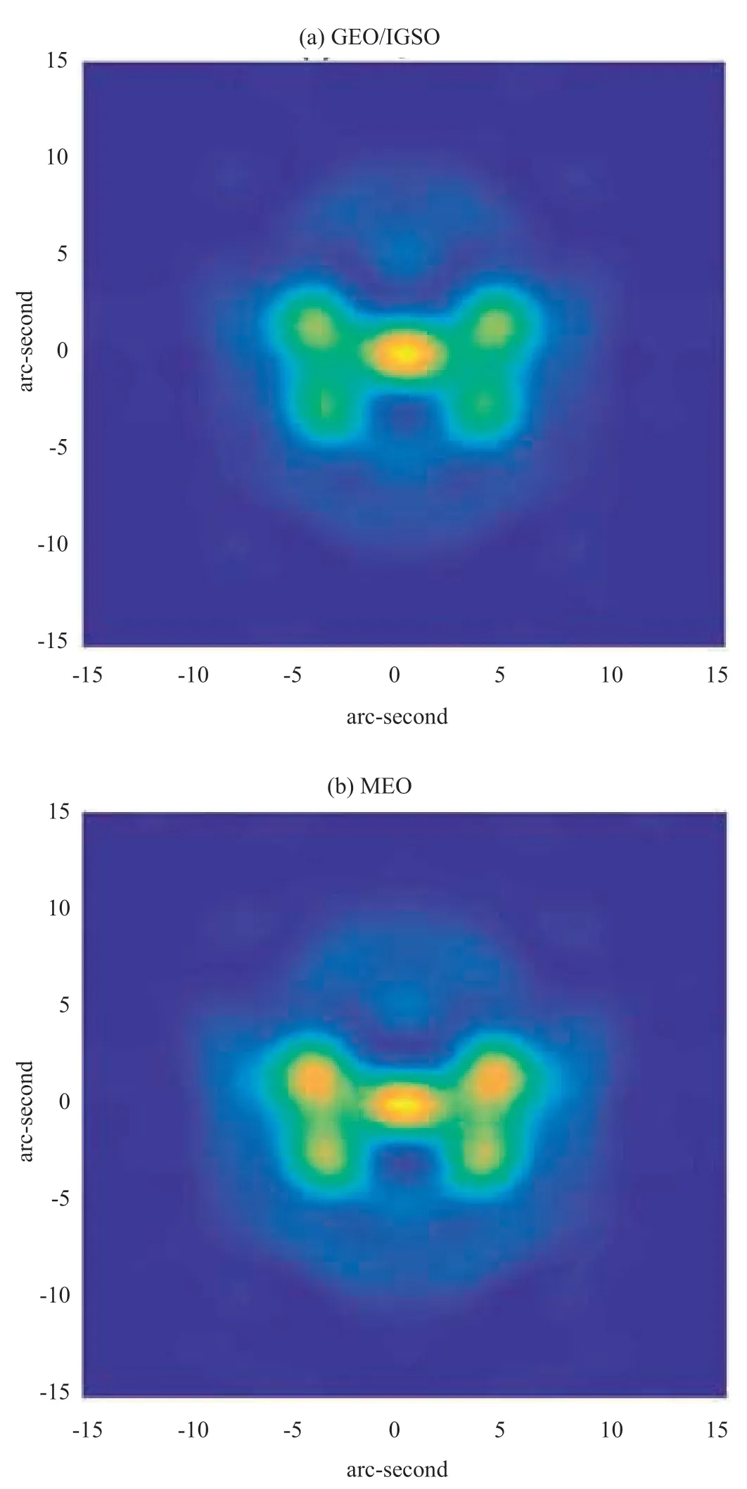
Figure 5 FFDP of cube corner of BDS GEO/IGSO and MEO satellites
3.3 The Far-Field Diffraction Pattern and Cross Section of LRAs
The far-field diffraction pattern (FFDP) is one of the major characteristics of LRAs.Using the cube-corner FFDP model[17],the simulated results of the FFDP for uncoated LRAs on BDS satellites at the wavelength of 632.8 nm are given in Figure 5.Figure 5(a) was obtained from the GEO/IGSO satellites and the result in Figure 5(b) was from the MEO ones.The X-axis and Y-axis were the field of view with the unit of arc-seconds.Due to the dihedral angle offset of corner cube,the FFDP would not be asymmetric.However,the far-field intensity distribution was concentrated within the range of 10 arc-seconds,which made compensation of velocity aberration for GEO/IGSO and MEO satellites and were sufficient to receive laser echoes on ground.Laser ranging data at ground SLR stations has validated the above design of FFDP.
The cross section of a LRA is also an important factor for SLR,especially for BDS GEO/IGSO satellites,which require a large cross sections of LRAs to compensate for the longer distance and weaker laser pulse echo signals[16].The cross sections of LRAs from several GNSS GEO satellites are shown in Figure 6.The cross sections of LRAs for the BDS GEO BeiDou satellites span from 160 to 60 million square meters at the ground at an incidence angle of 0˚-15˚,which meet the requirements for SLR measurements.

Figure 6 Cross sections of LRAs for different GNSS GEO satellites
4 GLOBAL SLR OBSERVATIONS OF BDS SATELLITES AND APPLICATIONS
4.1 SLR Observations of BDS Satellites
As a coordinator of the Chinese SLR network,SHAO is making an effort to promote SLR technology and international cooperation on BDS satellites.Under the rule of the global SLR tracking campaign leaded by the ILRS,the laser tracking of BDS satellites was implemented with the coordinator of the ILRS and SHAO.The BDS M1 satellite was launched in 2007,and has participated in the global laser observation scheme since 2008.The laser data was used for the technical validation for BDS[18].For strengthening laser tracking to GNSS satellites,the laser ranging GNSS experiment (LARGE) campaign under ILRS was performed by NASA,Russian,Chinese,and European networks[19-20].The working objectives of the LARGE group were:
Defining an operational GNSS tracking strategy that addresses all proposed requirements from all interested parties.
Clarifying outstanding ILRS and Internatioral GNSS Service(IGS) issues with the GNSS satellites and ground stations.
In the frame of LARGE campaign,each GNSS constellation nominates a few GNSS satellites which will be used,as shown in Table 2.
For the BDS constellation,four MEO satellites have participated in the LARGE campaign.Figure 7 gives the observational statistics of BDS satellites by sub-networks in the first LARGE campaigns in 2018,and Figure 8 shows the site distribution of global SLR tracking for GEO/IGSO/MEO satellites.
4.2 Applications of BDS SLR Data
The most frequent used application for SLR tracking data for GNSS satellites is the computation of SLR range residuals.By using the global SLR network,the global coverage and long-arc observation data can be acquired for the orbit determination,giving the accuracy assessment of broadcasting ephemeris,and the orbit correction.
(1) Orbit determination by using SLR data
Global laser observation can obtain long passes,providing laser ranging data to meet the requirements for precise orbit determination.The orbits of the BDS satellites are obtained from global SLR observation data[21].The orbit accuracy of BDS satellites could be evaluated with the orbit consistency of two adjacent 7-day solutions during the overlapping interval.Figure 9 and Table 3 show the orbit overlap errorsfor BDS-2 I5 and M3 satellites.In Figure 9,the horizontal axis represents time;while the vertical axis represents orbit errors of the BDS satellite orbits in three components with radial/trace/normal (R/T/N).
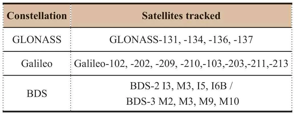
Table 2 GNSS satellites which joined into LARGE campaign

Figure 7 Observations of BDS satellites by subnetworks in the first LARGE campaign in 2018
The accuracy of BDS satellite orbits determined from the global laser data has reached a meter level.This provides the basis for the applications of SLR technology for BDS satellites.Due to the satellite-dependent characteristics of SLR tracking data,it can generally be used to assess the accuracy of satellite data derived from other tracking systems.Figure 10 shows the range residual between the SLR data (observed) and microwave frequency orbit (computed) for BDS-3 M2 (C20),M3(C21),M9(C29) and M10(C30) satellites.It can be seen that the range residual is on the level of sub-decimeter.

Figure 8 The distribution of global SLR tracking sites for GEO/IGSO/MEO satellites

Table 3 The orbit residual (RMS) of R/T/N component for BDS-2 I5 and M3 satellites
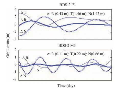
Figure 9 Errors of orbits for BDS-2 I5 and M3 satellites

Figure 10 Differences between SLR range from microwave orbits orbit (computed) from BDS-3 M2(C20),M3(C21),M9(C29) and BM10(C30) satellites
(2) SLR data used in the validation of broadcast ephemeris error
The SLR directly measures the distance between the ground station and the LRAs on satellites.An estimation of the satellite distance can be obtained through the correction of data.These correction parameters include the station tide,plate movement,eccentricity,atmospheric delay,general relativity and center of mass of the satellites[22-23].The broadcast ephemeris accuracy can be checked directly by comparing with the corrected high-precision SLR data.The accuracy of the broadcast ephemeris from BDS-2 G1,I3,I5 and M3 satellites has been evaluated based on global SLR data,the results are shown in Figure 11.The results show that the accuracy of broadcast ephemeris is about 0.8 m for BDS-2 G1 satellite,0.9 m for BDS-2 I5 satellite,and 1.09 m for BDS-2 M3 satellite,and 1.43 m for BDS-2 I3 satellite.The accuracy of broadcast ephemeris in radial component was better than 1.5 m.The errors of BDS broadcast ephemeris were analyzed through direct comparison with precision ephemeris products and the RMS errors of the R component of orbit were smaller than 1m for all BDS satellites,which confirms the evaluating results from the SLR data.

Figure 11 Evaluation of the accuracy of broadcast ephemeris for BDS-2 G1(a),I3(b),I5(c),M3(d) satellites
5 APPLICATION OF LTT TECHNOLOGY
The LTT could be performed with a dedicated laser detector and timer,through combining the time tagged epoch of the transmitted laser pulse,the received laser pulses and the returned laser pulses based on the satellite and ground timescale respectively,so the time difference and the relative frequency difference can be calculated between the satellite and ground clock[24-26].
5.1 Design of LTT Payloads
The LTT technology was developed by the SHAO from the 1980s[24],where the prototype of the LTT module was designed and developed in 2005 to perform the ground tests by simulating the satellite and ground clocks[27].The feasibility of the LTT measurements were verified and improvements were made for the BDS satellites.
The LTT payload was successfully developed for the first BDS MEO experimental satellite called M1 in 2007[28].Between 2010-2012,multiple sets of onboard LTT payloads were developed.New LTT payloads were developed based on the experimental BDS-2 M1 satellite[29].The LTT payload mainly consists of a laser detector and timer.To detect the weak laser signal at the distance of the satellite orbit,a chip was designed for single photon mode detection.The detector payloads had two alternative pinholes which could produce a wide field of view (FOV) (23° for MEO,15° for IGSO at the elevation of>30°) and a narrow field of view (17° for MEO,11° for IGSO at the elevation of >50°).
The detection rate could be improved by adopting a smaller FOV and applying gate control.Table 3 shows the results from the BDS M1 MEO satellite with only the fixed FOV in the case when outside the Earth's shadow.It is evident that Geiger-mode detector with a different FOV helps to increase the detection rate in the high level background noise.
In addition,the timers onboard the BDS satellites produced 20 pps gate signal from a 10 MHz signal which is supplied by the satellite clock.It measures the time interval between the 20 pps and the arrival of the laser pulse.The timer was realized by a field programmable gate array (FPGA) and a time digital converter (TDC) unit.Time measurements can be performed with the single shot precision of 100 ps because of precision of the TDC chip[30].

Table 3 The comparison of performance of onboard laser detector on BDS-2 M1 and M3 satellites
5.2 LTT Measurements
The BDS-2 I1,I3 and M3 satellites with the LTT payloads were launched between 2010-2012,and the LTT measurements were performed using a dedicated SLR system on the ground.During the LTT measurements,a fixed range gate was adopted with a gate width of about 70 ns to gate the detectors on the satellites.To detect the laser signal at the satellite,the time of firing of the laser on the ground must be accurately calculated to make the laser pulse arrive just after the gate pulse,taking into account the laser flight time,the predicted clock difference,and the system time delays.
In addition,a laser fire controller was also developed to precisely control the laser fire time.The laser system in the ground SLR system runs in active Q-switch mode and the jitter of firing time of the laser pulse could be controlled within 10 ns,which met the requirements of controlling precision for the laser transmitting time on ground[31].

Figure 12 LTT measuring results from the BDS satellites
Figure 12 shows the LTT measurement results from the BDS satellites,the X-axis is the time and Y-axis is the clock difference,the root mean square (RMS) of clock difference by linearity fitting is 293.5 ps.
LTT measurements were conducted successfully for the BDS satellites which are shown in Table 4,the clock differences between the satellite and ground clock have been calculated with the RMS of approximately 300 ps.Figure 13 shows the analysis results of LTT data with a time stability of 20 ps at 500 s.
From the results of LTT measurements,the measuring precision and time stability were limited by the performance of the onboard detector,timer and LRAs.However,LTT measurements for BDS satellites have successfully given the confidence in further development of LTT technology for the next generation of BDS,which could include improving the onboard LTT payload,modifying the operation mode and reducing the error of the laser transmitting link.The measuring precision of the LTT measurements can be improved.Among them,the precision of onboard detector and timer could be improved to about 30 ps and 10 ps respectively,the signature LRAs could be at millimeter level and the laser pulse from the ground can be 10 ps and the LTT measuring precision can achieve the level of 60 ps[32].

Figure 13 The time stability of LTT measurements from BDS-2 M3 satellite

Table 4 LTT measurements from BDS-2 I3 satellite
6 CONCLUSIONS
SLR technology has been successfully applied to BDS satellites over more than 30 sets of LRAs and the dedicated SLR system.The precise measurements of the distance to BDS satellites have implemented with the precision at centimeter level.The new generation of BeiDou satellites will also install LRA payloads.Based on SLR technology,the number of global SLR stations for tracking BDS satellites has increased and laser data obtained to determine the satellite orbit,validation of microwave orbit and the evaluation of broadcast ephemeris of the BDS satellites.The continuous SLR observations under the efforts of SHAO and ILRS will be continued and the significant impact on the development of BDS will be seen in future. LTT technology was developed for the first time for BDS by manufacturing several sets of onboard LTT payloads for BDS satellites.The LTT measurements between the BDS satellite and ground clock have been performed with a single shot precision of better than 300 ps,with a time stability of 20 ps@500 s.A new version of LTT payload with a detection precision of 30 ps and timing precision of 10 ps will be developed for the new generation of BDS system and Chinese Space Station project.
Acknowledgement
This work is supported by the BDS and the National Natural Science Foundation of China (Grant No.11503068,U1631240) and Shanghai Key Laboratory of Space Navigation and Position Techniques (Grant No.06DZ2101).CAS Key Technology Talent Program;Natural science fund of Shanghai(20ZR1467500);the Key Research Program of the Chinese Academy of Sciences(ZDRW-KT-2019-3-6);The authors thank ILRS for supports of tracking BDS satellites and are also grateful to M.Davis and M.Wilkinson for their works of performance analysis of LRAs on BDS satellites.
杂志排行

Aerospace China的其它文章
- Development and Innovation of BeiDou Navigation Satellite System
- Review and Prospect of LM-3A Series Launch Vehicle As Space Express for BDS
- Application of Medium-Voltage Fully-Regulated High-Power EPS on the BDS-3 Satellites
- Satellite Autonomous Integrity Monitoring of BDS and Onboard Performance Evaluation
- Application and Prospect of BeiDou Navigation Satellite System in the Transportation Industry
- Research on GPS Construction and Technology Development