Design of synthetic aperture radar low-intercept radio frequency stealth
2020-02-26CHANGWenshengTAOHaihongLIUYanbinandSUNGuangcai
CHANG Wensheng,TAO Haihong,LIU Yanbin,and SUN Guangcai,*
1. National Laboratory of Radar Signal Processing,Xidian University,Xi’an 710071,China;2. School of Physics and Optoelectronic Engineering,Xidian University,Xi’an 710071,China
Abstract: Not confined to a certain point, such as waveform, this paper systematically studies the low-intercept radio frequency(RF)stealth design of synthetic aperture radar (SAR) from the system level.The study is carried out from two levels.In the first level,the maximum low-intercept range equation of the conventional SAR system is deduced firstly, and then the maximum low-intercept range equation of the multiple-input multiple-output SAR system is deduced.In the second level,the waveform design and imaging method of the low-intercept RF SAR system are given and verified by simulation.Finally,the main technical characteristics of the lowintercept RF stealth SAR system are given to guide the design of low-intercept RF stealth SAR system.
Keywords: synthetic aperture radar(SAR) imaging,low-intercept radio frequency (RF) stealth, low-intercept range, low-intercept waveform.
1.Introduction
The meaning of “low-intercept radio frequency stealth”is to use a variety of technical measures to break the loop of the other party’s electronic countermeasure(ECM)equipment,so that the other party cannot detect radar signals or is unable to distinguish the radiation threat. The low-intercept radio frequency stealth includes two levels.Firstly,it is hard for the ECM equipment to find a working radar.Secondly,it is difficult to sort and identify the radiation signal of the working radar for the ECM equipment.
To improve the stealth performance of aircraft platform,on the one hand, the radar cross-section (RCS) of airborne synthetic aperture radar (SAR) should be reduced efficiently; on the other hand, the low-intercept radio frequency stealth design of airborne SAR is required. If the SAR system does not carry out targeted low-intercept radio frequency stealth design, it may be easily intercepted by the ECM equipment when the radar is working, so that the position of the flying platform is exposed and the stealth characteristics of the flying platform are meaningless.Therefore,the design of low-intercept radio frequency stealth has become a research hotspot. However, most of the current studies focus on the design of low-intercept waveforms[1–8].There is relatively few research on the design of low-intercept radio frequency stealth in the radar system from the system level[9–11],and fewer research on the design of low-intercept radio frequency stealth in the SAR system.Only[6]and[8]have studied the design of low-intercept radio frequency stealth waveform in the SAR system from the angle of waveform coding.
In this paper,a low-intercept radio frequency stealth design method for the SAR system is proposed from the SAR system level for the first time. Firstly, based on the range equation of the SAR system and the interception range equation of the ECM equipment to the emitter target, the maximum low-intercept range equation of the SAR system is deduced. Then, through the analysis of the maximum low-intercept range equation of the SAR system,the low-intercept radio frequency stealth design method of the SAR system is drawn at the first level that it is difficult to be detected by the ECM equipment when the SAR system is working.Then,based on the analysis of the reconnaissance process of ECM equipment, the waveform design and imaging method of the low-intercept SAR system is given at the second level that the radiation signal of the SAR system is difficult to be sorted and recognized by the ECM equipment.Finally,on the basis of summarizing the above two parts, the main technical characteristics of the low-intercept radio frequency stealth SAR system are given.
2.Low intercept distance calculation of SAR system
SAR imaging is two-way, and the interception of radar signals by the ECM equipment is one-way. On the surface, it seems almost impossible for the SAR system not to be detected by the ECM equipment when the SAR system is radiating signals.However,compared with the interception mechanism of the ECM equipment,the SAR system has certain advantages, that is, the radiation signals of the SAR system are self-matching and coherent accumulation,and these features are blind and unknown to the ECM equipment before the radiation signals of the SAR system are intercepted.Generally,the ECM equipment can only detect the radiation signals of the SAR system based on video detection.Therefore,there is a balance point between the imaging range of the SAR system and the interception range of the ECM equipment to SAR radiation signals at a certain distance[12].
The SAR range equation based on the noise equivalent backscattering coefficientNEσ0is as follows[13].

wherePtis the radar emission peak power, ratio is the radar duty ratio,Atis the effective area of radar transmitting antenna,Aris the effective area of the radar receiving antenna.λis the carrier wavelength,Rsis the radar action range,andkis a Boltzmann constant.Tis the radar working temperature,NFis the radar system noise figure,LSis system loss,vis the platform flight speed, andθis the grazing angle.ρris the range resolution,and its computational formula isρr=kr ·C/2Bi, whereCis the speed of light,Biis the signal bandwidth, andkris the pulse pressure broadening coefficient.
According to the radar equation[14],the power spatial spectral densityPof the radar radiation signal at the distanceRfrom the radar is

whereKis the antenna pattern factor.The value of the factor in the angle region of the main lobe of the radar transmitting antenna is 1,and the value of the factor in the angle region of the side lobe is less than 1, which is the corresponding side lobe level of the transmitting antenna in the angle region.
The bandwidth of the channel of the ECM equipment isBj,the effective area of the receiving antenna of the ECM equipment isAj, and the loss of the receiving link of the ECM equipment isLj.
When the radar radiation signal bandwidthBiis less than the channel bandwidthBjof the ECM equipment ,the received radar radiation signal powerPrby the ECM equipment at the distanceRfrom the radar is as follows:

When the radar radiation signal bandwidthBiis greater than the channel bandwidthBjof the ECM equipment,the received radar radiation signal powerPrby the ECM equipment at the distanceRfrom the radar is as follows:

IfPr≥Prmin, it means that the ECM equipment can intercept radar radiation signals,wherePrminis the detection sensitivity of the ECM equipment. Usually, the signal bandwidth of a high resolution SAR system is much greater than that of the channel bandwidth of the ECM equipment.Therefore,from(2)and(4),the equation of the interception rangeRjof the ECM equipment to radiation signal of the SAR system can be obtained,as follows:

The interception factor [15]αis the ratio of the interception rangeRjto the radar action rangeRs,as follows:

According to(1),(5)and(6),the following formulas can be obtained:

The interception factorαis equal to 1,which indicates that the interception range of the ECM equipment to radiation signals of the SAR system is equal to the action range of SAR. The action range of the SAR system atα= 1 is defined as the maximum low-intercept range of the SAR system. That is to say, when the action range of the SAR system is less than its maximum low-intercept range,it is difficult for the ECM equipment to intercept the radiation signal of the SAR system when the SAR system is working.Therefore,the maximum low-intercept range equation of the SAR system is given by

It is known from(8)that the followings hold.
(i)Rmax-LPI∝ratio
Increasing duty ratio can increase the maximum lowintercept range of the SAR system.Traditional monostatic SAR is limited by the isolation between transmitters and receivers, so that the duty ratio cannot reach 100%. The bistatic SAR [16] uses the distance between transmitters and receivers to enhance the isolation between transmitters and receivers to achieve continuous wave work,so the duty ratio can reach 100%which effectively improves the maximum low-intercept range of the SAR system,as shown in Fig.1.

Fig.1 Bistatic continuous wave SAR working diagram
(ii)Rmax-LPI∝Ar
The maximum low-intercept range of the SAR system can be effectively improved by increasing the effective area of the radar receiving antenna.
In general,SAR systems use the entire antenna areas to achieve high-resolution imaging of the ground. However,most current SAR systems today are multi-function radars.In order to enhance the action range of the lower resolution imaging mode and detection accuracy of the ground moving target indicator (GMTI) mode, a large-azimuth aperture antenna is frequently applied. However, the highest azimuth resolution is 1/2 of the antenna azimuth in the strip mode. To achieve a higher-resolution image in the strip mode, the SAR system mostly uses the way of broadening the azimuth transmitting beam and the azimuth receiving beam of the antenna.Beam broadening means that the effective area of the antenna is reduced. Only if the azimuth beam of the antenna is broadened and the receiving antenna is divided into several sub arrays, the area of the whole receiving antenna can be used to achieve a higherresolution image in the strip mode by using digital beam forming(DBF)to form receiving multiple beams[17]that will effectively improve the maximum low-intercept range of the SAR system in the higher-resolution strip mode.
(iii)and
Reducing the system lossLSand noise figureNFhelps improve the maximum low-intercept range of the SAR system.
(iv)
Lower platform speed is helpful to improving the maximum low-intercept range of the SAR system.
(v)
When the ECM equipment receives the radiation signal from the side lobe of the transmitting antenna of the SAR system,reducing the side lobe of the transmitting antenna of the SAR system is beneficial to improving the maximum low-intercept range of the SAR system.
According to (8), when the duty ratio of the SAR system, the effective area of receiving antenna, the carrier wavelength, the noise figure and the system loss are determined, the maximum low-intercept range of the SAR system under a specific flight platform is determined for the specific parameters of the ECM equipment, independent of the effective area of transmitting antenna and the peak emission peak power of the SAR system. However,it can be seen from (1) that the action range of the SAR system is related to the product of the effective area of the transmitting antenna and the peak emission power.
Effective isotropic radiated power (EIRP) is equal to the product of the peak emission power and transmitting antenna gain. The EIRP corresponding to the maximum low-intercept range of the SAR system can be calculated from(8)and(1),which is denoted as EIRPLPI.The EIRP corresponding to the maximum action rangeRmaxof the SAR system may be much higher than EIRPLPI,and thenRmax>Rmax-LPI,α >1 and the interception range of the ECM equipment to the radiation signal of the SAR system is greater than the maximum action range of the SAR system. That is to say, the maximum action range of the SAR system may be much greater than its maximum lowintercept range.
In order to make this conclusion clearer, the SAR system parameters in Table 1 and the ECM equipment parameters in Table 2 below will be used for calculation and analysis as an example. In Table 1,andIn Table 2,The SAR system uses the phased array antenna so that its transmitting gain and emission peak power can be flexibly controlled.
According to (1) and (5), the action range of the SAR system and the interception range of the ECM equipment to radiation signal of the SAR system are calculated, as shown in Fig.2.

Table 1 SAR system parameters

Table 2 ECM equipment system parameters

Fig. 2 Action range curve of SAR system and interception range curve of ECM equipment
As seen from Fig.2,when the EIRP of the SAR system is less than the EIRP corresponding to 25.8 km,the interception range of the ECM equipment to the radiation signal of the SAR system is less than the action range of the SAR system. When the EIRP of the the SAR system is greater than the EIRP corresponding to 25.8 km, the interception range of the ECM equipment to the radiation signal of the SAR system is greater than the action range of the SAR system, so the maximum low interception distance of the SAR system is 25.8 km.
By substituting the parameters shown in Tables 1 and 2 into(8),Rmax-LPI = 25.8 km is obtained,which verifies the correctness of(8).
In addition, Fig. 2 also shows that when the ECM equipment receives the radiation signal of the SAR system from the main lobe of the transmitting antenna of the SAR system,the maximum low-intercept range of conventional SAR system is usually less than the maximum action range, which proposes the demand to improve the maximum low-intercept range.
3.Improvement of maximum low-intercept range
If the maximum low-intercept range of the SAR system is to reach the maximum action range of the SAR system itself, it is necessary to disperse the equivalent radiation power of the radar for the ECM equipment,and then synthesize the dispersed radiation power at the radar receiver to improve the maximum low-intercept range of the SAR system.
The multiple input and multiple output (MIMO) SAR based on orthogonal signals synthesizes the transmitting pattern of the radar at the receiving end [18], which effectively reduces the equivalent radiation power at the transmitting end of the radar and achieves radio frequency stealth.The principle diagram is shown in Fig.3.

Fig.3 Working principle diagram of MIMO radar
For MIMO SAR systems based on orthogonal signals,the transmitting patterns of each orthogonal T/R subarray are not synthesized in space, so the effective area of the radar transmitting antenna is only the effective area of a single orthogonal transceiver array.However,after operating transmitting patterns of each orthogonal T/R subarray at the receiving end of the SAR system, the transmitting pattern of the whole antenna is synthesized.
Therefore,for MIMO SAR systems based on orthogonal signals,(1)and(5)are modified as follows:

whereNis the number of orthogonal T/R subarrays in the MIMO SAR systems.
From (9) and (10), the maximum low-intercept range equation of the MIMO SAR system based on the orthogonal signals can be derived as
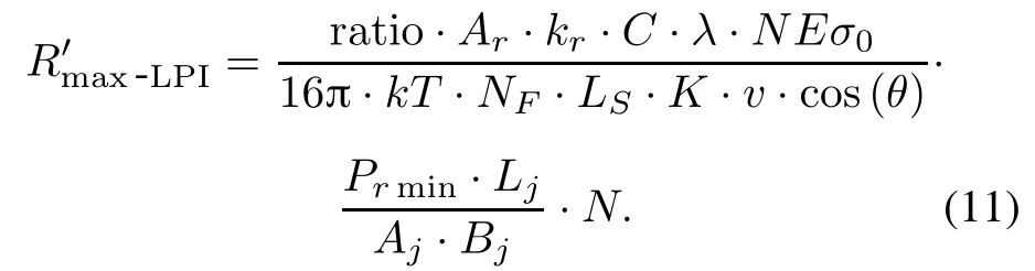
From (11), the maximum low-intercept range of the MIMO SAR systems based on the orthogonal signals isNtimes that of conventional SAR systems.
Taking a 4-input and 4-output MIMO SAR system based on Doppler division multiple access (DDMA) orthogonal signals[19]as an example,the transmitting gain of a single subarray is 1/4 of the transmitting gain of the total array in Table 1.Other system parameters are the same as those in Table 1,and the parameters of the ECM equipment are the same as those in Table 2.
According to (9) and (10), the action range of the 4-input and 4-output MIMO SAR and the interception range of ECM equipment to the radiation signal of the 4-input and 4-output MIMO SAR are calculated,as shown in Fig.4.
Fig. 4 shows that the maximum action range of the 4-input and 4-output MIMO SAR is greater than the interception range of ECM equipment to the radiation signal of the 4-input and 4-output MIMO SAR.
By substituting the relevant parameters into (11),= 103.2 km is obtained,which is greater than the maximum action range of the 4-input and 4-output MIMO SAR.Thus,the correctness of(11)is verified.
It can be seen from the above that the MIMO SAR system based on orthogonal signals can effectively improve the maximum low-intercept range of the SAR system,but the ECM equipment is non-cooperative compared with the SAR system after all.

Fig.4 Action range curve of 4-input and 4-output MIMO SAR system and intercept range curve of ECM equipment
When the low-intercept SAR system designed for specific parameter ECM equipment faces the ECM equipment with a higher sensitivity, the power of the radar radiation signal received by the ECM equipment will still be higher than the detection threshold of the ECM equipment,so the radiation signal of the SAR system has the risk of being intercepted.Therefore,the low-intercept SAR system also needs to adopt the low-intercept waveform to further reduce the probability of interception of its radiation signal.
4.Low-intercept waveform design
4.1 SAR imaging algorithm with low-intercept waveform
Guessing and understanding are two completely different concepts.The purpose of radio frequency stealth is to keep the ECM equipment in constant speculation until it is too late for it to find the target [20]. The key to the effective jamming of ECM equipment against radar is whether it can separate the single radar signal from the random staggered signal stream in the high-density signal environment,and identify the radar signal to be jammed,that is,signal sorting. With the development of technology,the signal sorting algorithm has gradually evolved from single parameter sorting to multi-parameter correlation sorting[21].The basic flow chart of multi-parameter signal sorting is shown in Fig.5.
From Fig. 5, it can be seen that the ECM equipment is mainly based on the pulse repetition interval(PRI),carrier frequency (CF), pulse width (PW), pulse amplitude (PA)and other characteristic parameters of the radar radiation signal, and it analyzes the modulation form of the radar radiation signal to realize signal sorting, and it generally needs a certain number of pulses with constant characteristic parameters.If the characteristic parameters and modulation form of the SAR radiation signal are pulse-to-pulse agile and the modulation form is noise-like, the difficulty of ECM signal sorting can be greatly enhanced.

Fig.5 Basic flow of multi-parameter signal sorting
SAR imaging is essentially related to antenna motion,through transmitting and receiving signals at different locations, and coherent processing on the returns, to equivalently synthesize a large array and achieve resolution improvement.Therefore,after correctly compensating the array synthesis error caused by the change of radar signal parameters, the realization of high resolution SAR imaging will not be affected.
However, conventional SAR imaging algorithms [22]are designed based on constant radiation signals and must be adjusted accordingly.The SAR imaging algorithm with PRI,PW,PA,modulation form and other signal parameters of pulse-to-pulse agility is shown in Fig.6.

Fig.6 SAR imaging algorithm with agile PRI,PW,PA and modulation form
The “amplitude correction” in the algorithm flow corrects the amplitude of each echo pulse according to the change of the PW and PA of the radiation signal, avoiding azimuth modulation caused by the change of the PW and PA of the radiation signal.“Azimuth resampling”corrects non-uniform sampling in azimuth caused by changes in PRA [23]. “Range cell migration correction based on chirp-Z transform(CZT)”corrects range cell migration in high resolution imaging for radiation signals whose modulation form is not linear frequency modulation[24].
4.2 Generation method for agile signal parameters and simulation
4.2.1 Generation method for agile PRI
The key to generating agile PRI is to generate a random number sequence that is used to represent PRI.At present,a widely used method is to generate random number sequence by mathematical method on the computer.The polar coordinate method is the most commonly used method to generate a random number sequence that obeys the standard normal distribution, and the calculation steps are as follows.
Step 1Produce two independent identically distributedU(0,1)random numbersU1andU2.
Step 2LetVi= 2Ui -1 (i= 1,2), and calculate

The random number sequence that obeys the standard normal distribution can be obtained by the above method.For a random variable that obeys the Gaussian distribution, its linear function still obeys the Gaussian distribution. Therefore, the Gaussian distribution of the variable can be obtained by the linear transformation of the standard normal distribution. For example, according to the polar coordinate method,the random number sequenceXthat obeys the standard normal distribution can be firstly generated. Then,Y=σX+μthat obeys the Gaussian distribution whose mean value isμand variance isσ2can be obtained.
It can be assumed that the PRI is a random number sequence that obeys the Gaussian distribution,its mean value is 1/FSandFSis sampling frequency. Letσbe an adjustable constant. Then, the PRI that obeys any Gaussian distribution can be obtained by changingσ.
4.2.2 Generation method for agile PW and PA
The method to generate the agile PW and PA is similar to that of the agile PRI. The random number sequence that obeys the standard normal distribution can be firstly generated. Then, the Gaussian distribution of the number sequence can be obtained by the linear transformation of the standard normal distribution.
4.2.3 Generation method for noise-like modulation signals
Since the PRI and the PW are agile, a finite set of noiselike modulation signals can be generated,these noise-like modulation signals are stored in a code table.As the radar works, noise-like modulation signal can be randomly selected from the code table to transmit.
4.2.4 Simulation
The parameters for simulation are shown as follows: the bandwidth is 150 MHz, the wavelength is 0.031 3 m,the speed of the radar is 100 m/s, the reference range is 8 000 m, and the sampling points in both range and azimuth are 1 024.
The pulse repetition frequency (PRF), PW and PA are agile by using the above methods. PRF is the inverse of PRI, which can be simulated instead of PRI. As shown in Figs. 7(a)–7(c), PRF increases or decreases randomly with 650 Hz as the center in every azimuth sampling point,PW increases or decreases randomly with 20 μs as the center in every azimuth sampling point, and PA increases or decreases randomly with 3 dB as the center in every azimuth sampling point.The noise-like modulation signal is shown in Fig.7(d).
By transmitting the noise-like modulation signal in Fig. 7(d), the echo data shown in Fig. 8(a) is generated. Then, the imaging results processed by the algorithm shown in Fig. 6 are obtained, which are shown in Figs. 8(b)–8(d). The target points focus well in imaging results shown in Fig. 8(d), which verifies the validity of low-intercept waveform design.


Fig.7 Radiation signal with agile PRI,PW,PA and noise-like modulation signal


Fig.8 Imaging simulation result of multi-parameter agile signal
5.Main technical characteristics of low-intercept radio frequency stealth SAR system
The design of low-intercept radio frequency stealth SAR has been demonstrated from two levels in the preceding sections. The first level is that if SAR adopts a large receiving antenna, continuous wave operation and MIMO system based on orthogonal signals, it is difficult for the ECM equipment to detect the radiation signal of the SAR system.The second level is that it is difficult for the ECM equipment to sort and recognize the radiation signal of the SAR system when multiple characteristic parameters of the radiation signal of the SAR system are jointly agile.
The main technical characteristics of the low-intercept radio frequency stealth synthetic aperture radar system can be summarized.
(i)Receiving multiple beams by using DBF;
(ii)Continuous wave operation based on bistation/multistation;
(iii)MIMO configuration;
(iv)The PRI,PW,PA and modulation forms of the radiation signal are pulse to pulse agile.
6.Conclusions
Based on the analysis of the research status of lowintercept radio frequency stealth in the radar system, the design method of low-intercept radio frequency stealth in the synthetic aperture radar system is studied from the system point of view for the first time.It is studied from two levels.In the first level,the maximum low-intercept range equation of conventional SAR systems is deduced firstly,and then the maximum low-intercept range equation of the MIMO SAR system is deduced. In the second level, the waveform design and imaging method of the low-intercept radio frequency stealth SAR system are given. Finally,based on the research of these two levels, the main technical characteristics of the low-intercept radio frequency stealth SAR system are given.
杂志排行

Journal of Systems Engineering and Electronics的其它文章
- A method based on Chinese remainder theorem with all phase DFT for DOA estimation in sparse array
- A simplified decoding algorithm for multi-CRC polar codes
- Compressive sensing based multiuser detector for massive MBM MIMO uplink
- Joint 2D DOA and Doppler frequency estimation for L-shaped array using compressive sensing
- Carrier frequency and symbol rate estimation based on cyclic spectrum
- Attributes-based person re-identification via CNNs with coupled clusters loss