探空火箭减阻杆气动特性分析
2020-02-04常耀予刘帆张家齐
常耀予 刘帆 张家齐
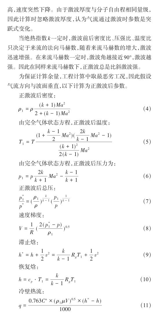
摘要:为了研究减阻杆对探空火箭气动力特性,通过采用SST两方程湍流模型、有限体积法求解N-S方程,对探空火箭高速流场进行数值模拟。计算结果显示,减阻杆能有效减小火箭阻力。亚跨声速(Ma0.8~1.2)最大减阻25%;高超声速(≥Ma6)阶段,最大减阻量35%,减阻效果随迎角增大而降低,到12°迎角时减阻量为12%。压跨声速及高超声速全箭升阻比增量随马赫数增大均增加,高超声速阶段升阻比增大18%。同时采用工程方法结合数值预示结果,评估减阻杆带来的气动热影响,结果显示,气动支杆的存在使得端头的平均热流密度下降了51%,并与飞行试验结果进行对比分析。计算得到热流结果与飞行实测热流结果相当,热环境预示比较准确,对于高超声速阶段的飞行器被动热防护技术研究具有良好的指导价值。
关键词:减阻杆;气动热;气动力;高超声速;探空火箭
中图分类号:V211.73文献标识码:ADOI:10.19452/j.issn1007-5453.2020.11.010
近半个世纪,高超声速流动机理及控制方面较低速流动领域取得的进展较少[1],高超声速流动控制主要集中在减阻防热控制方面,控制方法为在钝头体头部安装减阻杆进行流场重构,减小气动阻力[2]。
减阻杆属于被动流动控制,通过前伸支杆外推钝头体头部弓形激波,转换为强度较弱的锥形斜激波,在头部形成低压回流区,减小激波阻力,降低表面热流。减阻杆以其显著的减阻和降热效果,在国外导弹上已经实现工程应用。美国飞行速度Ma24的三叉戟Ⅱ型彈道导弹(UGM-133 Trident-II,1990年服役)采用伸缩式尖针状减阻杆[3]。导弹出水发动机点火不久,加速度触发伸出减阻杆,到位后锁定,这种设计便于导弹头部在保证装填空间的前提下,同时兼顾高速飞行时的低阻特性,导弹在高超声速情况下减阻达52%,同时导弹射程增加了550km[4]。
由于减阻杆外形为针状结构,尖针杆会带来防热和流场不稳定问题[5-6],本文研究了“球形头+圆锥”减阻杆构型下[7],探空火箭在高超声速下的气动力特性与气动热特性。通过仿真手段对比分析了气动力减阻效果,同时采用工程算法及飞行试验对减阻杆带来的降热效果进行评估,为后续工程应用提供设计依据。
1计算方法
1.1气动力计算方法

2探空火箭外形
火箭采用轴对称气动布局,任务飞行器采用“球头+圆锥”气动外形,球头前端布置减阻杆;控制舱、发动机及尾段为柱段形式;空气舵和燃气舵共轴布置,均采用X形布局。火箭气动布局如图1所示。
根据目前对减阻杆的气动布局特性研究,减阻杆采用“端头帽+细长杆”布局[8],设计参数主要有减阻杆长度、端头直径及减阻杆直径,如图2所示。
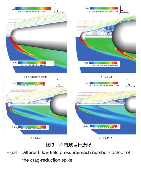
根据图3减阻降热的计算结果,优化设计,选取减阻杆长度为锥段球头直径的两倍,端头帽为球头直径的0.3倍,减阻杆直径为球头直径的0.1倍[9]。
根据火箭几何参数,减阻杆端头半径45mm;圆柱长度555mm,直径30mm;减阻杆后部的锥段前缘半径150mm,半锥角12°,如图4所示。

3减阻杆气动特性结果分析
3.1减阻杆气动力分析
气动力计算网格采用混合网格,为准确模拟边界层内黏性对气动力的影响,采用Octree八叉树法构建空间四面体网格,在壁面沿法向生成9层棱柱形网格,头部及尾段采用密度盒加密,总网格量1145万。
此种网格划分方法、网格量已经在OS-X0,OS-X1两个型号飞行试验中进行验证,数据准确可靠,如图5所示。
仿真计算设置压力远场边界条件,选择理想气体介质,计算马赫数从Ma0.6开始到发动机关机点Ma6,典型马赫数状态流场的马赫数和压力云图[10-11]如图6和图7所示。
支杆顶部聚集起高压区,有效降低了端头附近的压力,从而降低了端头阻力。
对减阻杆的减阻效果进行评估,亚跨声速(Ma0.8~1.2)最大减阻25%;高超声速(Ma6)阶段,最大减阻量35%,减阻效果随迎角增大而降低,到12°迎角时减阻量为12%。压心位置飞行全程变化量在1%以内,马赫数6小迎角状态压心前移3%,减阻杆对纵向压心的影响如图8所示。亚跨声速及高超声速全箭升阻比增量随马赫数增大均增加,高超声速阶段升阻比增大18%[12-14],如图9所示。
3.2减阻杆气动热分析
根据工程算法,采用减阻杆后,支杆及端头的热流密度随时间的变化曲线如图10所示。支杆顶点最大热流密度1738kW/m2,端头最大热流密度952kW/m2。
减阻杆的存在使得端头的平均热流密度下降了51%,对于高超声速阶段的飞行器被动热防护技术研究而言,首飞通过热流传感器获得的相关数据,对比数值预示结果,将具有良好的指导价值[15]。
飛行试验中,热流传感器布置如图11所示。热流传感器采用JCR4-4-6型传感器,参数值范围0~800kW/m2,采样频率40Hz,测量误差±5%。


根据传感器位置布局,飞行试验测得100s内高热流段柱段热流。图12为理论计算与测量热流对比图,由图可见,工程计算热流与测量热流一致性较好。从对比图中可以看出,工程计算热流与实测热流相当,热环境预示较准确[16-20]。
4结论
通过分析,得出以下结论:
(1)本文通过仿真手段对比分析了减阻杆的减阻效果,通过工程算法分析了减阻杆的降热效果。
(2)通过仿真手段计算结果得到减阻杆的减阻效果在高超声速阶段最大减阻量35%。
(3)通过工程算法计算得到不同部位的热流与飞行试验测得热流数据规律一致,相差最大为21.7%。
参考文献
[1]Kremeyer K,Reilly M P,Miley G H.Lines of energy deposition for supersonic/hypersonic temperature/drag-reduction and vehicle control[R].AFRL-RZ-ED-TP-2009-359,2009.
[2]Sun X,Guo Z,Huang W,et al. Drag and heat reduction mechanism induced by a combinational novel cavity and counterflowing jet concept in hypersonic flows[J]. Acta Astronautica,2016,126:109-119.
[3]Crawford D. Investigation of the flow over a spiked-nose hemisphere-cylinder[R]. NASATN-D-118,1959.
[4]Motoyama N,Mihara K,Miyajima R,et al. Thermal protection and drag reduction with use of spike in hypersonic flow[R]. AIAA2001-1828,2001.
[5]Mehta R C. Flow field computations over conical,disc and flat spiked body at Mach 6[R].AIAA2009-325,2009.
[6]Menezes V,Saravanan S,Reddy K P J. Shock tunnel study of spiked aerodynamic bodies flying at hypersonic mach numbers[J]. Shock Waves,2002,12(3):197-204.
[7]Menezes V,Saravanan S,Jagadeesh G. Experimental investigations of hypersonic flow over highly blunted cones with aerospikes[J].AIAAJournal,2003,41(10):1955-1966.
[8]Kulkarni V,Kulkarni P S,Reddy K P J. Drag reduction by a forward facing aerospike for a large angle blunt cone in high enthalpy flows[R]. Shock Waves,Springer Berlin Heidel berg,2009:565-570.
[9]Gauer M,Paull A. Numerical investigation of a spiked blunt nose cone at hypersonic speeds[J]. Journal of Spacecraft and Rockets,2008,45(3):459-471.
[10]Boylan D E,Hahn J S,Sims W H. Drag on blunt bodies with and without spikes in low-density hypersonic flow[J]. AIAA Journal,1965,3(2):365-366.
[11]Kalimuthu R,Mehta R C,Rathakrishnan E. Experimental investigationonspikedbodyinhypersonicflow[J]. Aeronautical Journal,2008,112(1136):593-598.
[12]Asif M,Zahir S,Kamran N. Computational investigations aerodynamic forces at supersonic/hypersonic flow past a blunt body with various forward facing spikes[R]. AIAA 2004-5189,2004.
[13]GerdroodbaryMB,HosseinalipourSM.Numerical simulation of hypersonic flow over highly blunted cones with spike[J].ActaAstronautica,2010,67(1):180-193.
[14]Elsamanoudy M,Ghorab A,Hendy M. Drag reduction using spiked-aerodisk & reattachment ring for hypersonic hemispherical bodies[C]//15th International Conference on Aerospace Sciences&Aviation Technology,2013.
[15]TahaniM,KarimiMS,Motlagh A M.Numerical investigation of drag and heat reduction in hypersonic spiked blunt bodies[J]. Heat and Mass Transfer,2013,49(10):1369-1384.
[16]Yadav R,Guven U. Aerothermodynamics of a hypersonic projectilewithadouble-diskaerospike[J]. Aeronautical Journal,2013,117(1195):913-928.
[17]Joshi S. Effect of double disk aero-spikes on aerothermodynamics of blunt body at Mach 6.2[J]. International Journal of Applied Engineering Research,2016,11(1):366-376.
[18]Ahmed M Y M,Qin N. Surrogate-based multi-objective aerothermodynamic design optimization of hypersonic spiked bodies[J].AIAAJournal,2012,50(4):797-810.
[19]Ahmed M Y M,Qin N. Recent advances in the aerothermodynamics of spiked hypersonic vehicles[J]. Progress in Aerospace Sciences,2011,47(6):425-449.
[20]Srulije J,Gnemmi P,Runne K. High-pressure shock tunnel experiments and cfd calculations on spike-tipped blunt bodies[J].AIAAJournal,2002,5(1):2918-2926.
(責任编辑王为)
作者简介
常耀予(1994-)女,硕士,工程师。主要研究方向:流体力学。
Tel:18600818348E-mail:changyaoyu@onespacechina.com刘帆(1984-)男,博士,高级工程师。主要研究方向:火箭总体设计。
张家齐(1984-)男,硕士,高级工程师。主要研究方向:流体力学。
Analysis of Aerodynamic Characteristics Using Spikes of Sounding Rocket
Chang Yaoyu*,Liu Fan,Zhang Jiaqi
Onespace Technology Group Co.,Ltd.,Beijing 100176,China
Abstract: In order to study the aerodynamic of sounding rocket with drag-reduction spike, the Navier-Stokes equations are solved by finite volume method based on the k-ωSST turbulent flow model. On this basis, the flow field of the hypersonic projectile is simulated. The calculation results show that the spike can effectively reduce the drag of sounding rocket. The study shows the maximum drag reduction of sub-sonic speed is 25%, and the maximum drag reduction of hypersonic phase is 35%. The drag reduction effect decreases with the increase of the angle of attack, and the drag reduction amount is 12% when the angle of attack is 12 degrees. The calculation results show there is a positive correlation between drag ratio and Mach number. Specifically, the drag ratio increases by 18% in hypersonic phase. At the same time, the engineering method is used to evaluate the aerothermal effect by the drag reduction spike, and compared with the flight test results. The theoretical value of heat flow is equivalent to the measured value of heat flow in the flight test, and the thermal circumstance prediction is comparatively accurate.
Key Words: drag-reduction spike; aerodynamic heat; aerodynamic force; hypersonic; sounding rocket
