Nonlinear Correction of a Hydraulic Propulsion System Used in Deep-sea Work-Class ROVs
2019-12-30yng
-,-,,-yng
(a.School of Naval Architecture,Ocean and Civil Engineering;b.School of Mechanical Engineering,Shanghai Jiao Tong University,Shanghai 200240,China)
Abstract: The purpose of this paper is to improve the control performance of deep-sea work-class ROVs (remotely operated vehicles) by improving the nonlinear characteristics of the hydraulic propulsion system controlled by proportional pressure-reducing valves used in the ROVs. When the desired propeller thrust is small, the backpressure of the system and nonlinearities of both the hydraulic valves and drive boards result in strong nonlinear characteristics of the hydraulic propulsion system,and the nonlinear characteristics can be greatly improved by supply of the same initial pressure on both ends of the hydraulic motor.Underwater experiments show the nonlinear characteristics of the hydraulic propulsion system and verify the accuracy of the simulation model of the propulsion system.The results of numerical simulations demonstrate the influence of the nonlinear characteristics of the propulsion system on the control performance of the ROVs and the improvement in the control performance after a correction to the nonlinearities.
Key words:deep-sea work-class ROVs;hydraulic propulsion system;proportional pressure reducing valve;nonlinear correction
0 Introduction
Deep-sea work-class ROVs (remotely operated vehicles) are playing an increasingly important role in the exploitation of ocean resources, ocean science research, military applications, etc.[1-2]. The propulsion system is the power unit of the ROVs and its nonlinear characteristics have a large impact on the control performance of the ROVs.Therefore,it is crucial to improve the nonlinear characteristics of propulsion system for the design of the control system of ROVs[3-7].
There are two kinds of propulsion systems used in ROVs based on different drive modes.One is an electric propulsion system, and the other is a hydraulic propulsion system. With a propulsion mechanism directly driven by an electric motor, the electric propulsion system has the advantages of a simple structure and a high efficiency and is widely used in small-and medium-power ROVs[8]. The hydraulic propulsion system uses a hydraulic pump as its power source, and the hydraulic motor is driven by the pump. Compared with the electric propulsion system, the hydraulic propulsion system can achieve a stepless speed regulation over a wide range, is less affected by load change, can easily realize overload protection, and has a better adaptive capacity to water depth.Moreover,the fluidity and lubricity of hydraulic oil are favourable for discharging heat and prolonging the life of the components. The hydraulic propulsion system has a faster dynamic response because the pressure of hydraulic motor can be generated in a short time, and the output torque could peak instantaneously. However, the current rise time of an electric motor is long, which results in a time constant of the electric propulsion system that is much larger than that of the hydraulic propulsion system. The time constant of the hydraulic propulsion system is usually less than 200 ms, but the time constant of the electric propulsion system is 1-2 s at the same power[9].Furthermore,as most underwater operating manipulators are driven by hydraulic systems,no additional power source is required for ROVs using a hydraulic propulsion system.Based on these advantages,a hydraulic propulsion system is widely used in deep-sea work-class ROVs. The maximum diving depths of the‘KAIKO’and‘Triton’ROVs built by JAMSEC (Japan Agency for Marine-Earth Science and Technology)and Perry Slingsby are 10 911.4 m and 4 000 m, respectively. The maximum diving depths of the‘Hysub 5000’,‘Ventana’, and‘ROPOS’ROVs designed by ISE (International Submarine Engineering) are 5 000 m, 2 000 m, and 5 000 m, respectively. The maximum diving depths of the‘SeaDragon’and‘SeaHorse’ROVs built by SJTU(Shanghai Jiao Tong University)are 3 500 m and 4 500 m,respectively[10-11].All of these deep-sea ROVs use a hydraulic propulsion system.
Currently,the main hydraulic propulsion system used in ROVs are throttle-type and volumetric-type speed regulation systems[12-13]. A hydraulic propulsion system controlled by a servo valve is a kind of volumetric-type speed regulation system. The displacement of the hydraulic motor is controlled by a servo valve, and not only a displacement control mechanism is used to change the angle of the swash plate of the motor,but also a high-precision angle sensor is used to construct a closed-loop system[14]. This kind of propulsion system is used in the‘SeaDragon’,‘Ventana’and‘Triton’ROVs. Although a servo valve control system exhibits a high efficiency, it has a low speed of response. Moreover, the large energy consumption, high cost and strict requirement on cleanliness of fluid medium of the servo valve control system mean that system maintenance is more time-consuming and expensive. A throttle-type speed regulation system, also known as a valve-controlled system, is used in the‘Hysub’ROV. A hydraulic propulsion system controlled by proportional pressure reducing valves is a type of throttle-type speed regulation system. The pressure difference between the inlet and outlet of the hydraulic motor can be changed by adjusting the input currents of the proportional pressure-reducing valves,and the torque and speed of the thruster change as the pressure difference changes.The throttle-type speed regulation system has the advantages of a high speed of response,easy manufacturing and maintenance, and low cost, although it has a low efficiency because of throttling losses.
The propulsion system is dealt with as a proportional link in most studies on the control method of ROVs because its nonlinear characteristics are ignored. However, the inner pressure feedback apparatus of proportional valves has many complex nonlinear factors, which result in the complex nonlinear characteristics of the propulsion system,and most hydraulic motors have no rotation feedback function and are open-loop systems[15-17]. Therefore, the nonlinear correction of a hydraulic propulsion system controlled by proportional pressure-reducing valves is necessary.
1 Mathematical model of ROVs
The research objective in this paper is a deep-sea work-class ROV (see Fig.1), being developed by Shanghai Jiao Tong University. The mass and size of the ROV are 5 600 kg and 3.2×1.9×2.3 m,respectively,and the maximum working depth is 3 000-4 000 m.
An earth-fixed reference frameE-XYand a body-fixed reference frameo-xyare always defined when analysing the horizontal motion of ROVs,as indicated in Fig.2.The dynamic model of 3 DOFs(degrees of freedom)describing the ROV performance is given as[18]
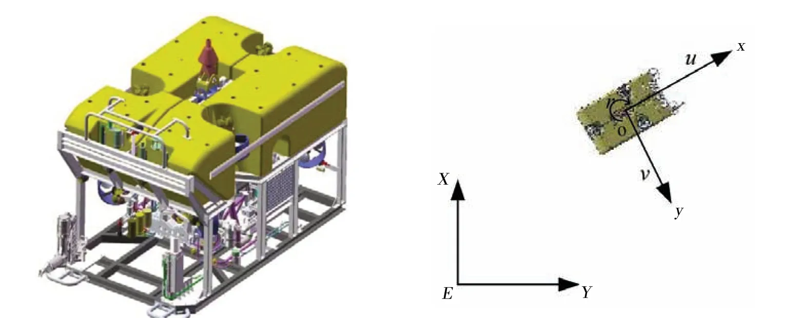
Fig.1 Deep-sea work-class ROV Fig.2 Earth-fixed and body-fixed reference frames

whereq=[u v r]T;uandvare the linear velocities inox- andoy-axial directions, respectively;ris the angular velocity in yaw;T=[ ]TxTyN;TxandTyare the forces acting on the ROV along theox-andoy-axes,respectively;Nis the moment about the vertical axis;M,C(q)andD(q)are the inertia, Coriolis, and damping matrices, respectively. The parameter matrices are:


wheremis the mass andIzis the moment of inertia about the vertical axis of the ROV;Xu̇,Yv̇,andNṙrepresent the inertial hydrodynamic coefficients;Xu,Yv,Nr,Xu||u,Yv||vandNr||rrepresent the viscous hydrodynamic coefficients.
The kinematic equations of the ROV can be expressed as

whereη=[X Y ψ]Tis the position and attitude vector of the ROV in theE-XYcoordinate system;XandYare the position coordinates in theEX- andEY-axes andψis the heading angle of the ROV.
2 Hydraulic propulsion system of a single propeller
The schematic diagram of the hydraulic propulsion system of a single propeller controlled by proportional pressure-reducing valves used in the deep-sea work-class ROV is shown in Fig.3.The pressure at either end of the fixed displacement bidirectional hydraulic motor is controlled by a proportional pressure-reducing valve. Once the pressure difference is generated, the propeller will rotate and generate thrust acting on the ROV. A variable displacement unidirectional hydraulic pump provides pressure to the entire system.
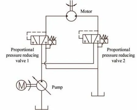
Fig.3 Schematic diagram of the hydraulic propulsion system of a single propeller
The control principle block diagram of the hydraulic propulsion system of a single propeller is shown in Fig.4,whereτdandτrepresent the desired propeller thrust and the actual propeller thrust, respectively;u=[u1u2]Trepresents the output vector of the controller;u1andu2are the input signals of Drive Boards 1 and 2, respectively;I1andI2are the input currents of Proportional Pressure-reducing Valves 1 and 2, respectively;P1andP2are outlet pressures of Valves 1 and 2, respectively;Mdenotes the output shaft torque of the hydraulic motor and ΔP=P1-P2denotes the pressure difference.
Ifu1>u2,thenI1>I2,P1>P2,ΔP>0,M>0,Valve 1 acts as a pressure-reducing valve,while Valve 2 acts as a pressure relief valve, and the hydraulic motor and propeller rotate in a forward direction, i.e.,τ>0. Ifu1<u2, thenI1<I2,P1<P2, ΔP<0,M<0, Valve 1 acts as a pressure relief Valve, while valve 2 acts as a pressure-reducing valve, and the hydraulic motor and propeller rotate in the reverse direction,i.e.,τ<0.

Fig.4 Control principle block diagram of the hydraulic propulsion system of a single propeller
2.1 Conventional control method of the hydraulic propulsion system of a single propeller
When the nonlinear characteristics of the drive boards and the proportional pressure-reducing valves are ignored, the output current of the drive boards and the outlet pressure of the proportional valves are:

whereI=[I1I2]T;P=[P1P2]T;K1=Imax/umax;umaxis the maximum input signal of drive boards, andImaxis the output current of the drive board corresponding toumax;K2=Pmax/Imax;Pmaxis the output pressure of the proportional pressure reducing valve corresponding toImax.
The damping moment acting on the propeller provided from water and the propeller thrust are taken as nonlinear functions of water density,propeller speed,propeller diameter,thrust coefficient and torque coefficient,as expressed by Eqs.(9)and(10),respectively[19].

whereKTandKMdenote the thrust coefficient and torque coefficient,respectively;andD,ρ,andndenote the propeller diameter, water density, and shaft speed of motor or propeller speed, respectively.
The output shaft torque of a hydraulic motor can be expressed as

whereDmrepresents the displacement of the motor.
The damping moment acting on the propeller provided from water is equal to the output shaft torque of the hydraulic motor in equilibrium,i.e.,Mw=Mm,based on ignoring the viscosity damping force acting on the motor. Therefore, from Eqs.(9-11) the propeller thrust is obtained as:

whereK3=(KT/KM)×(Dm/D).
When the backpressure of the system is zero, i.e., ΔP=P1or ΔP=P2, from Eqs.(7-8)and(12),the propeller thrust can be expressed as

The values of the parameters of the propulsion system are shown in Tab.1, whereKT1andKT2are thrust coefficients when the propeller rotates in the forward and reverse directions, respectively,KM1andKM2are torque coefficients when the propeller rotates in the forward and reverse directions, respectively[14].Imaxis 374 mA andPmaxequals 212 bar, which can be obtained from the specifications of the drive boards and proportional pressure-reducing valves, whenumaxis 100. Therefore, according to Eq.(13) the conventional control law of a hydraulic propulsion system of a single propeller can be calculated as


Tab.1 Parameters of the propulsion system
2.2 Nonlinear correction of the hydraulic propulsion system of a single propeller
The control performance of the control law expressed as Eq.(14) is worse, although it is simple, because the nonlinear characteristics of the drive boards and proportional pressure-reducing valves are not considered, and the backpressure of the system is ignored. Therefore, the nonlinear correction of the hydraulic propulsion system is necessary.
2.2.1 Underwater experiments on a hydraulic propulsion system of a single propeller
The drive boards used in the experiments were developed at Shanghai Jiao Tong University, and the model M33 proportional pressure-reducing valves produced by Wandfluh company were used. The experiments were conducted using National Instruments Real Time hardware and LabVIEWTMsoftware. The embedded real-time controller NI cRIO-9066 with a reconfigurable FPGA for the C series modules,an RS232 serial module NI 9870 with 4-ports,and a 16-bit analogue input module NI 9203 with 8-channels were used in the experiments. The physical map of these components is shown as Fig.5. The experiment principle schematic diagrams of the propulsion system of a single propeller are shown as Figs.3-4, and the experiment stand is shown as Fig.6.The sample time was 20 ms.

Fig.5 Physical map of the components used in the underwater experiment
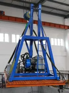
Fig.6 Experiment stand
Experiments were conducted on the drive board first, and the experiment principle schematic diagram is shown in Fig.7, where V and A represent the voltmeter and ammeter, respectively. The inherent resistance of the ammeter has a great impact on the results of experiment,and the experimental data after a correction of the inherent resistance are shown in Fig.8.
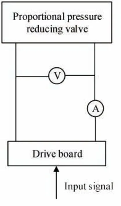
Fig.7 Experiment principle schematic diagram of a drive board
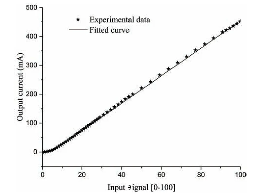
Fig.8 Experimental data of drive board and fitting result
When the input signalsuwere set atu1= 40 andu2= 0, the responses of Proportional Pressure-reducing Valves 1 and 2 in the underwater experiment are shown in Fig.9. When the input signalu1was ramped up from 0 toumax,u2= 0 in 55 s,the responses of Valves 1 and 2 in the underwater experiment are shown in Fig.10.

Fig.9 Step responses of the proportional pressurereducing valves
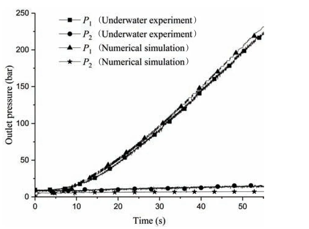
Fig.10 Ramp responses of the proportional pressure-reducing valves
Figs.8 and 10 show that the nonlinear characteristics of the drive board and the proportional pressure-reducing valves are obvious when the input signal is small.We can see from Figs.9 and 10 that the proportional valves have approximately a 10-bar dead zone, and there is approximately a 10-bar backpressure in the hydraulic propulsion system (P2≈10 bar). From Fig.9 it can be seen that the proportional valves have approximately an 80 ms delay,and the settling time is approximately 400 ms.
2.2.2 Numerical simulations on the hydraulic propulsion system of a single propeller
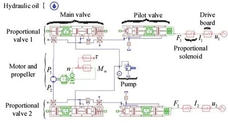
Fig.11 Simulation model of hydraulic propulsion system of a single propeller
A simulation model,as shown in Fig.11,was built in the AMESim to study the nonlinear characteristics of the hydraulic propulsion system. A proportional pressure reducing valve was disassembled(see Fig.12)to obtain its accurate internal structure and parameters, which are shown in Tab.2. Eq.(9)was used to calculate the damping moment acting on the propeller provided from water,and Eq.(10)was used to calculate the propeller thrust. Ignoring the dynamic performance of the drive board, its mathematical model is represented as Eq.(15),which is obtained using a polynomial segment fit method,and the fitting result is shown in Fig.8.
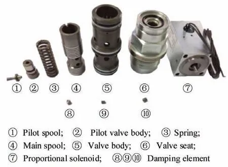
Fig.12 Structure of the proportional pressurereducing valve


Tab.2 Parameters of the proportional pressure-reducing valve
The relationship between the output forceFj(j= 1,2 )and the input currentIj(j= 1,2)of the proportional solenoid is shown in Fig.13, which is from the specification of the proportional pressure-reducing valve, whereIG= 680 mA represents the limiting current.The static mathematical model of the proportional solenoid can be obtained as Eq.(16) by approximating the curve in Fig.13 using a cubic polynomial fit method, and the fitting result is shown in Fig.13.
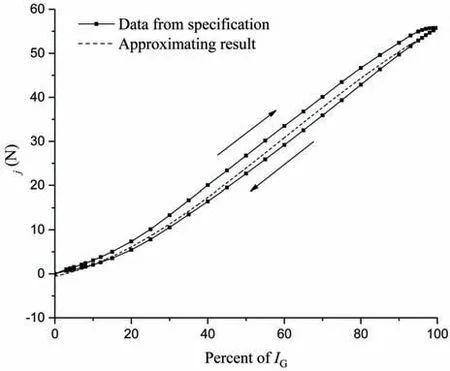
Fig.13 Force-current characteristics of proportional solenoid

When the input signal of the propulsion system in the numerical simulations is the same as that in the underwater experiments, the responses of Proportional Pressure-reducing Valves 1 and 2 in the numerical simulations are shown in Figs.9 and 10,from which it can be seen that the simulation model of the hydraulic propulsion system of a single propeller has a high precision and can be used in the following analysis of the paper.
2.2.3 A correction method of the nonlinearity
We defined Δu=u1-u2. The relationship between Δuandτcan be obtained from two simulation experiments. In the first simulation,u1= 0, andu2was ramped up from 0 toumaxin 0-55 s.In the second simulation,u2= 0,andu1was ramped up from 0 toumaxin 0-55 s.The results of the simulations are shown in Fig.14.
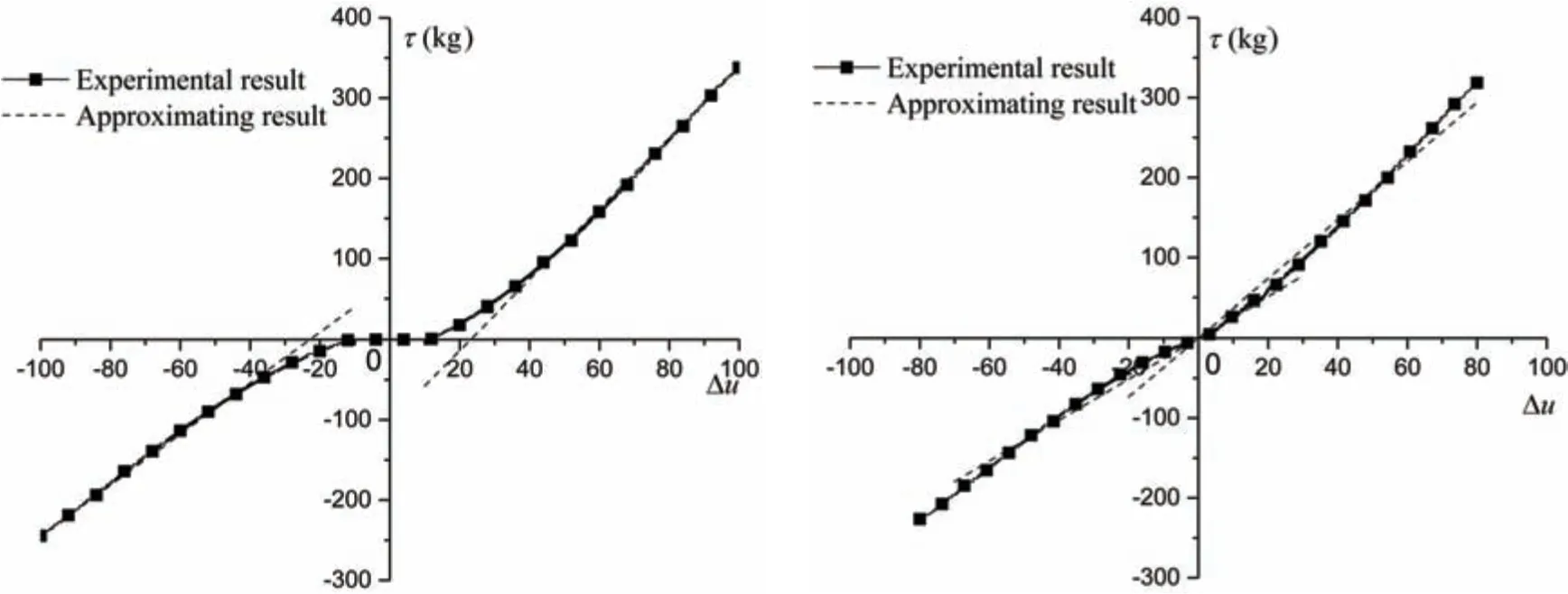
Fig.14 τ versus Δu(without an initial input signal) Fig.15 τ versus Δu(with an initial input signal)
When the initial signal,u0= 20, was added to the input, i.e.,u1=u0,u2was ramped up fromu0toumaxin 0-55 s during the first simulation. Additionally,u2=u0, andu1was ramped up fromu0toumaxin 0-55 s during the second simulation. The results of the simulations are shown in Fig.15.
As seen from Fig.14, the nonlinear characteristics of the hydraulic propulsion system are strong when |Δu|is small, and the propeller thrust is zero when |Δu|is less than 10. However,linear characteristics are preferable when |Δu|is large. The approximate experimental results when |Δu|is large(50 < |Δu|<100)using Eq.(17)are shown in Fig.14.

It can be seen from Fig.15 that the nonlinear characteristics of the hydraulic propulsion system can be improved obviously when |Δu|is small by adding an initial signalu0to the input.The approximate experimental results when |Δu|is small (0 ≤ |Δu|≤50) using Eq.(18) are shown in Fig.15.

Based on Eqs.(17-18), the control law of the hydraulic propulsion system of a single propeller after a nonlinear correction can be designed as

Fig.16 shows the ramp responses of the propeller thrust of a single propeller in the numerical simulation when the conventional control law (Eq.(14)) and the improved control law (Eq.(19)) were adopted. It can be seen that the control performance of the hydraulic propulsion system of a single propeller is clearly improved using the improved control law(Eq.(19)).
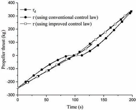
Fig.16 Ramp response of a single propeller
3 Thrust allocation
The condition that the maximum thrust of a propeller rotating foreword differs from that of the propeller rotating in reverse is not considered in the pseudo-inverse method, which has been widely used in the thrust allocation of an ROV[20]. To overcome this problem, a new thrust allocation method is proposed in this chapter.
The horizontal thrusters of the ROV are mounted askew in relation to the ROV’s main symmetry axes (see Fig.17), andτ1,τ2,τ3, andτ4are the propeller thrusts generated by the left front, right front, right rear, and left rear thrusters, respectively.βh= 45°is the angle between the thrusters and theox-axis,andlh= 1.208 9 m is the arm of the thrust about the vertical axis of the ROV. Therefore, the relationship between the desired resultant force and moment acting on the ROV and the desired thrust generated by each thruster can be expressed as

Fig.17 Layout of the horizontal thrusters of the ROV
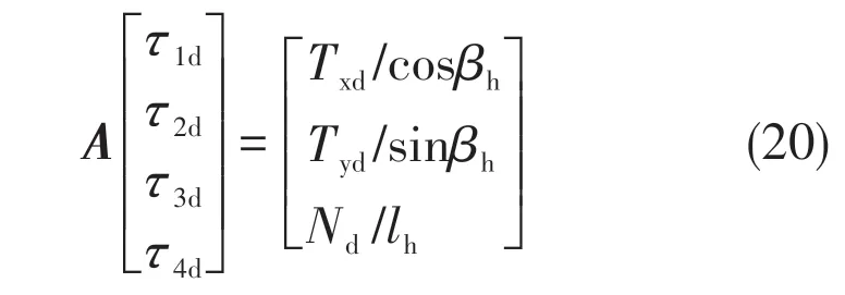
whereτ1d,τ2d,τ3d, andτ4dare desired thrust generated by the left front,right front,right rear,and left rear thrusters,respectively.TxdandTydare the desired forces along theox- andoy-axes, respectively, andNdis the desired moment about the vertical axis of the ROV.
Considering that the maximum thrusts of the thruster rotating forward and in reverse are not equal,the thrust can be expressed as

whereτ0=(|τfmax|- |τrmax|)/2;τfmaxandτrmaxare the maximum thrust values when the thruster rotates forward and when rotates in reverse,respectively;andτv=( )||τfmax+ ||τrmax/2.
Substituting Eq.(22)into(20)yields

Therefore

whereA+=AT(AAT)-1is the pseudo-inverse matrix ofA.
To ensureτidis in the range of[τrmax,τfmax],a scaling factor is defined

Therefore,the output of the thrust allocation is
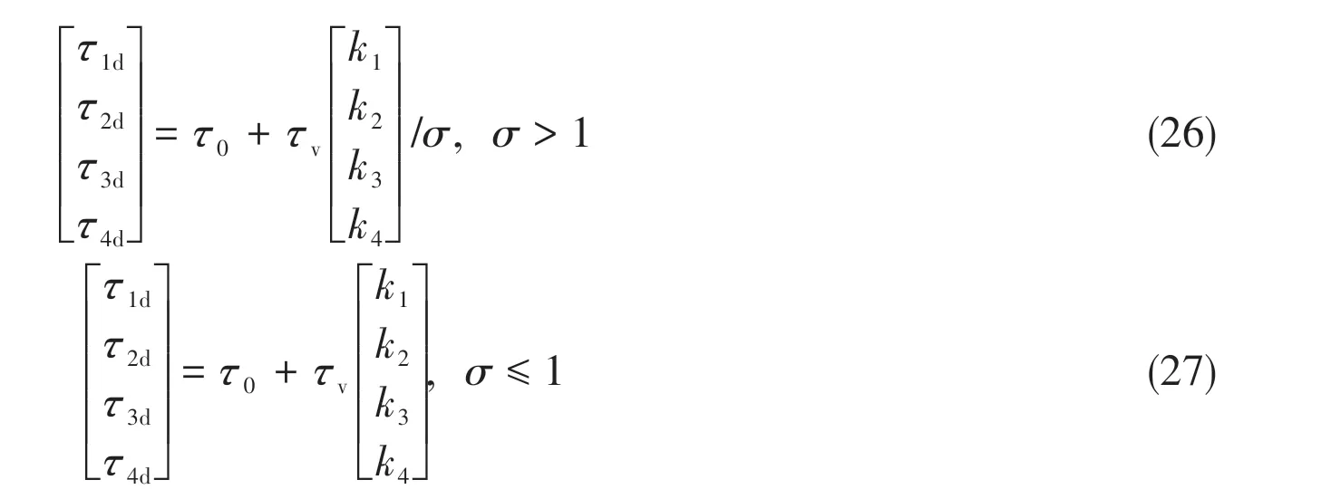
However, Eqs.(26-27) have a problem thatτd=[τ1dτ2dτ3dτ4d]Tis not zero whenTd=[TxdTydNd]is zero. To overcome this problem, whenTdis small the output of the thrust allocation is

The proposed thrust allocation is composed by Eqs.(26-28).
4 Effects of the hydraulic propulsion system on the control of the ROV
The closed-loop control principle block diagram of the ROV is shown in Fig.18, whereτ=[τ1τ2τ3τ4]T.
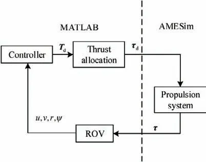
Fig.18 Control principle block diagram of the ROV
A numerical co-simulation was conducted on the control of the ROV with MATLAB and AMESim.The hydraulic propulsion system was built in the AMESim, and the calculations of the thrust allocation, control law and mathematical model of the ROV was built in the MATLAB (see Fig.18). The solver in the time-domain simulations was taken as the 3rd-order Bogacki-Shampine method, and the fixed step size was 20 ms. The nominal parameters of the ROV are shown in Tab.3.

Tab.3 Nominal parameters of the deep-sea work-class ROV
The experiments of the ramp and sinusoidal responses of the entire hydraulic propulsion system containing the thrust allocation module were conducted in the co-simulation. When the conventional control law (Eq.(14)) and the improved control law (Eq.(19)) were adopted, the responses of the entire hydraulic propulsion system in theox- andoy-axial directions are shown in Figs.19 and 20,respectively,and the response of the moment about the vertical axis is shown in Fig.21.
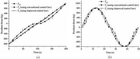
Fig.19 Response in the ox-axial direction
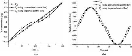
Fig.20 Response in the oy-axial direction
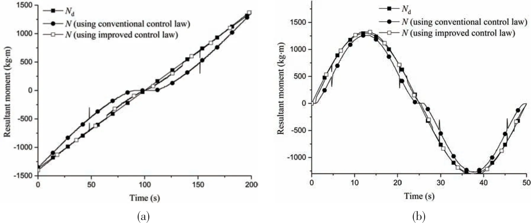
Fig.21 Response of the moment about the vertical axis
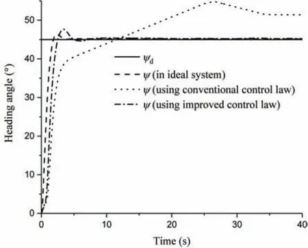
Fig.22 Step response of the heading of the ROV
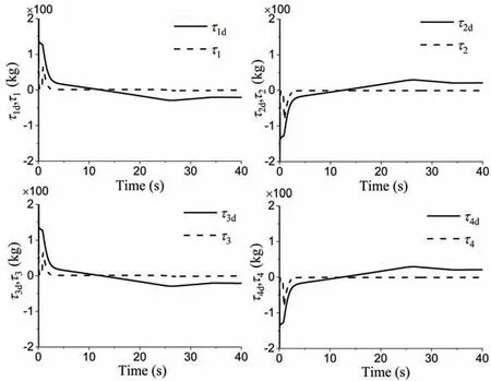
Fig.23 Responses of each thruster using the conventional control law

Fig.24 Responses of each thruster using the improved control law
The effects of the hydraulic propulsion system on the heading control of the ROV are shown in numerical co-simulation. The PID controller was used in the heading control, and the proportional,integral and differential coefficients were set asKP= 8 500,Ki= 55, andKd= 1 260, respectively. The desired headingψdwas 45°. The dynamic characteristics of the propulsion system were ignored, i.e.,Tis equal toTd, during the entire first simulation experiment.Additionally,the conventional control law(Eq.(14)) was adopted in the hydraulic propulsion system of each propeller during the second simulation experiment,and the improved control law(Eq.(19))was adopted in the hydraulic propulsion system of each propeller in the last simulation experiment. The results of these simulation experiments are shown in Fig.22. When the conventional control law (Eq.(14)) was adopted, the responses of each thruster are shown in Fig.23. When the improved control law (Eq.(19))was adopted,the responses of each thruster are shown in Fig.24.
From Figs.19-21,and upon comparison of Fig.23 with Fig.24,it can be seen that the tracking characteristics of the entire hydraulic propulsion system are improved obviously when the improved control law (Eq.(19)) was adopted in the hydraulic propulsion system of each propeller. Fig.22 shows that the dynamic characteristics of the hydraulic propulsion system affect the control of the ROV, and the control performance can be obviously improved by using the improved control law(Eq.)in the hydraulic propulsion system of each propeller.
5 Summary
The results of the underwater experiments showed that the nonlinear characteristics of the hydraulic propulsion system controlled by proportional pressure-reducing valves used in deep sea work-class ROVs are strong. A simulation model of the hydraulic propulsion system was built in the AMESim to study the nonlinear characteristics, and the accuracy of the model was proved by comparison of the results of the simulation experiments with those of underwater experiments. To correct the nonlinear characteristics, a new control law was proposed in this paper, and the results of the numerical simulations show that the nonlinear characteristics were significantly improved using the proposed control law. In the end, the results of the co-simulation experiments with MATLAB and AMESim validated that the control performance of the ROV can be obviously improved by correcting the nonlinear characteristic of the hydraulic propulsion system using the method proposed in this paper.
杂志排行
船舶力学的其它文章
- Nonlinear Wave Loads and Green Water Acting on a Ship in Severe Sea Conditions
- Application of Chebyshev Polynomials to Efficient Approximation of Frequency-Domain Infinite Depth Green Function
- Simulation of Irregular Wave Uplift Force on Horizontal Plate Structures
- Numerical and Experimental Study for SCR with Cable3D
- Nonlinear Numerical Simulation for Flexible Pipes Carcass Wet Collapse
- Analysis of Drilling Riser in Re-entry Operation Under Complex Currents
