Numerical Prediction of Propeller Noise Based on the‘Source Time-Dominant Algorithm’
2019-12-10PANYucunZHANGHuaixinZHOUQidou
PAN Yu-cun , ZHANG Huai-xin , ZHOU Qi-dou
(1. College of Naval Architecture and Ocean Engineering, Naval University of Engineering, Wuhan 430033, China;2. State Key Laboratory of Ocean Engineering, Shanghai Jiao Tong University, Shanghai 200240, China)
Abstract: A numerical study on the radiated noise of a marine propeller operating in uniform inflow was conducted. The flow field around the propeller was simulated based on the unsteady DES (Detached Eddy Simulation) equation. The far-field sound radiation from the propeller was predicted by an integral solution of FW-H (Fowcs Williams-Hawkings) equation in time domain. The ‘source timedominant algorithm’ was adopted to perform the retarded-time integral of the Farassat Formation 1A.This algorithm is more computationally efficient than the ‘retarded time algorithm’, due to its simpler calculation process. Moreover, it can easily collaborate with the input data given by CFD, since no interpolation of the source data is required. Both the computed open water performance of the propeller and the computed noise signals induced by the propeller are in good agreement with the available results in literatures. The characteristics of the noise induced by a single blade and the fourblade propeller are also discussed.
Key words: Ffowcs Williams-Hawkings equation; source time-dominant algorithm;underwater propeller noise
0 Introduction
Propeller noise is one of the most important sources of ship radiated underwater noise.Many researchers have made a large deal of efforts to identify the mechanism of the generation and propagation of propeller noise. Lighthill[1]developed the acoustic analogy by rearranging the Navier-Stokes equations into the form of wave equation, which has become the theoretical basis of flow induced noise. Ffowcs-Williams and Hawkings[2]used the gereralized functions to extend the Lighthill acoustic analogy model to predict sound generated by solid boundaries in arbitrary motion.
Farassat[3-5]derived an integral representation of the solution of the FW-H equation by using the Green function. This formulation makes the FW-H equation easy to implement numerically, hence it has been extensively used in predicting the aeroacoustic problems, such as helicopter rotor noise and fan noise. In recent years, some scholars have carried out research on marine propeller noise by FW-H equation. Seol et al[6]studied the noise from cavitating and non-cavitating propeller, by using a hybrid method where the flow field is analyzed with a panel method and the sound propagation is predicted by the FW-H equation. Mousavi et al[7]studied tonal and broadband hydrodynamic noise of non-cavitating underwater propeller by coupling LES method with the FW-H equation.
The time delay for the acoustic signal traveling from the source to the observer is a key aspect that should be treated carefully when we solve the FW-H equation, especially for the case of rotating blades. Nowadays, the most common method is the ‘Retarded-Time Algorithm’[8]. In that approach, the retarded time equation should be inversely solved to determine where and when the sound was emitted. In order to overcome this shortcoming, a novel method called ‘Source time-Dominant Algorithm’ was presented[9-10]. As a straight-forward approach,this algorithm is more computationally efficient, due to the simpler calculation process.
In this paper, Detached Eddy Simulation (DES) solver is used to obtain the transient flow information of the E779A propeller, and the Lighthill analogy is applied to predict the sound propagation. The ‘source time-dominant algorithm’ is adopted to deal with the retarded time problem. The feasibility of the approach in predicting the marine propeller noise is verified by comparing the computed results with the corresponding results in literatures.
1 Farassat formulation 1A of Ffowcs Williams-Hawkings equation
FW-H (Ffowcs Williams -Hawkings) equation is widely used in prediction of the noise generated by the general surfaces in arbitrary motion. As for an underwater propeller, the contribution of quadrupole term is usually considered to be negligible[6-7], thus, the FW-H equation[2]can be written as:

Farassat[3-5]derived an integral representation of the solution of the FW-H equation:

where


Eqs.(2)-(3) are known as Farassat Formulation 1A[3-5]. Here, p′ and p′ are thickness
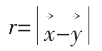
Formulation 1A is valid for arbitrary blade motion and geometry. As long as the motion characteristic of body and the loads acting on the body surface are obtained, the numerical integration above the boundary surface can be performed to evaluate the thickness and loading noise.
2 Source time-dominant algorithm
It is important to note in Eqs.(2)-(3) that the source strength is evaluated at the source time, but the solution we desired is described in observer time. As known, the distance between the sound source and the observer will lead to a time interval between the source time τ and the observer time t. Moreover, these time intervals are different for each equivalent source and observer combination. Hence this characteristic of sound propagation should be properly treated when we apply FW-H equation to predict propeller noise.

Although the ‘retarded-time algorithm’ has been extensively used, there are still some alternative approaches. In present paper, we chose the ‘source time-dominant algorithm’, which takes the source time as the primary time (i.e.,dominant) rather than the observer time. This algorithm uses the same formulation with the ‘retarded-time algorithm’, and the difference between them lies in the specific way of implementation. The schematic of the ‘source time-dominant algorithm’ was presented in Bres and Brentner[12], as shown in Fig.1.
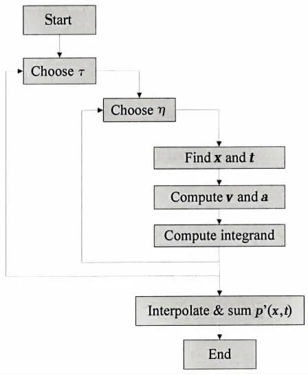
Fig.1 The schematic of the ‘source timedominant algorithm’
At the first step, the source time τ was chosen.

At the third step, according to the Eq.(2) and Eq.(3), the sound contributions from each source element on the blade surface were calculated.
At the fourth step, we must take proper measures in the reconstruction of the signals. On one hand, for a source element on the rotating blade, the distance between it and the observer is constantly changing due to its motion. Consequently, the signals emit from the source at an equally spaced discretization of the source time τ, but they arrive in the observer at an unequally spaced discretization of the observer time t. On the other hand, each point on the blade surface emits sound at the same source time τ, but the arrival time of these signals were different because the distance between each element and the observer is different. Hence, the arriving signal in the observer time series should be interpolated. In doing so, the contributions from all source elements can be summed at the same observer times. The detailed implementation of an interpolation scheme was described in Ref.[13].
From the above procedure, at least two advantages of the ‘source time- dominant algorithm’ can be found.
(1) Since in most cases the iterative solutions process of the retarded time equation can be avoided, the ‘source time-dominant algorithm’ would have higher efficiency than the ‘retarded- time algorithm’. In Bres’s article[12], the above two algorithms are used to compute the rotor noise of a maneuvering helicopter, the advantage of the former algorithm was demonstrated by the significant improvement in calculation times-a 55 times acceleration.
(2) In the ‘source time-dominant algorithm’, the hydrodynamic loads on blade described in source time can be directly used to calculate source strength. Hence, the discrete sequence of quantitative data given by the CFD calculation in equally spaced time is suitable for providing input data for sound calculation.
3 Procedures of CFD
The INSEAN E779A propeller was chosen as a test-case for CFD validation, whose geometry was described in Ref.[14]. The skewed four-blade model propeller has a diameter D=0.227 m, a pitch-to-diameter ratio P/D=1.1 and a forward rake angle of 4.05 deg.
The computational domain is divided into two sub-domains: the inner part is a small cylinder which contains the rotating propeller, the outer part is a large stationary cylinder which represents the farfield. The sliding mesh method was applied to simulate the rotating motion of the propeller. The inlet boundary was located at 2.5D in front of the propeller, the outlet boundary at 5D behind the propeller, the outer boundary extended to 5D in the radial direction.
The grids are generated using ANSYS ICEM software, the outer domain contains 1M of cells, and the inner domain contains 4M of cells. The multi-block hexahedral mesh was used to define the fluid domain, which allows detailed control of the mesh parameters and element quality.
The above mentioned inner domain is circumferentially split into quarters, and each passage region contains a blade. Consequently, to describe the region’s periodic boundaries, a pair of twisty surfaces should be created, as shown in Fig.2. The construction of the surfaces is based on the pitch and chord length at the individual radius and in each case the angle was turned around ±45 degrees over the suction and pressure side of the blade.

Fig.2 Overview of a single passage region
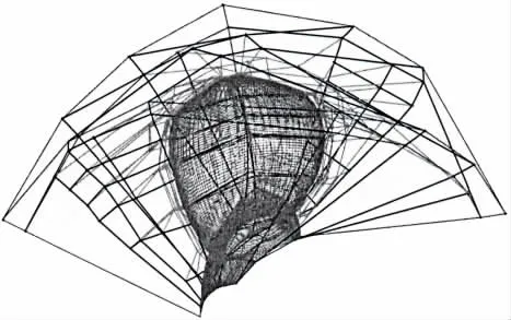
Fig.3 Block topology of a single passage region
The H and C topologies are combined to form the basis grid strategy of the single passage region. In addition, an O-grid topology was applied around the blade, which can properly control the mesh resolution in the vicinity of blade surface. The blade surface is tortuous in both the chordwise and spanwise directions, due to radial pitch distribution. To adapt the complicated geometry of blade surface, a large number of blocks were used to decompose the blade passage region. The resolution and the quality of the cells were adjusted through a proper node distribution on the edges of the blocks. When the grid of the single passage region was generated, the whole propeller grid can be easily regenerated by copying and rotating the single passage region.
4 Numerical results
4.1 Hydrodynamic solution of E779A propeller
To validate the hydrodynamic method, the hydrodynamic performance of an isolated E779A propeller in uniform inflow is compared with the experimental results[15]. Propeller diameter and rotational speed are, respectively, D=0.227m, n=1 500 r/min, and the advance coefficient varies with the advance speed.
In Fig.4, numerical results in terms of thrust coefficient Ktand torque coefficient Kqare compared with the experimental open water curves for a broad range of advance coefficient J. Compared with the model test results, the CFD result has discrepancies of less than 3% and 4% in the thrust and torque coefficients, respectively. The open water simulation shows acceptable accuracy at the design condition.
The steady RANS simulation was used to provide the open water performance of the propeller.However, to predict the propeller noise, the DES simulation should be performed to acquire the instantaneous information on the blades. In this paper,the DES based on the realizable k-ε turbulent model is adopted. The numerical results of steady RANS calculation can be used as the initial condition of the unsteady DES simulation.

Fig.4 Open water performance of E779A propeller
4.2 Acoustic result of a single blade
In this section, the acoustic pressure signatures induced by a single blade of E779A propeller are presented. The calculation was carried out at the same condition as used in Ref.[16].The radius, the advance speed and rotational speed are, respectively, R=1.0 m, U∞=8.395 m/s,n=286 r/min and the corresponding advance coefficient is J=U∞/nD=0.88. The sound observer is located in the propeller disk plane, at a distance d0=2R from the blade tip. The unsteady flow of rotating propeller is analyzed by discretizing each propeller revolution into 360 time steps.When the averaged hydrodynamic loads reach a quasi-steady state, the process of extracting the unsteady quantities over the blade surface would begin. These recorded quantities, such as the pressure, velocity, coordinates, area and normal vector of every element on the blade surface, would be provided to the Eqs.(2)-(3) as input data to compute the radiated noise.
Fig.5 shows the time histories of thickness noise, loading noise and total noise radiated from a single blade. The sound pressure amplitude of thickness noise is much lower than that of loading noise. That is, the loading noise is the dominant component of total noise.
In Fig.6, a satisfactory agreement between the noise from the single bladed E779A propeller predicted by the present approach and those in Ref.[16] is found. The waveforms of the sound pressure history of the two results are similar, however, the difference is found in term of the sound pressure peak intensity. In conclusion, the present approach is reliable for numerical prediction of the flow noise of rotating blade.
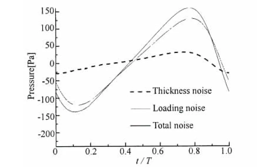
Fig.5 Acoustic pressure signals for thickness,loading and total noise at observer

Fig.6 Comparison of the predicted noise with the result in literature
4.3 Acoustic result of the four-bladed E779A propeller
In above section, the noise radiated from a single blade was investigated. Here, the test case was the four-bladed E779A propeller. The propeller operation parameter was adjusted in consonance to the Ref.[17]. The diameter, the advance speed and rotational speed are, respectively, D=0.227 m, U∞=4.029 25 m/s, n=1 500 r/min, hence the corresponding advance coefficient is J=0.71.
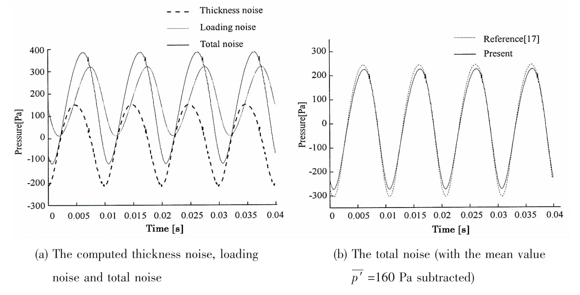
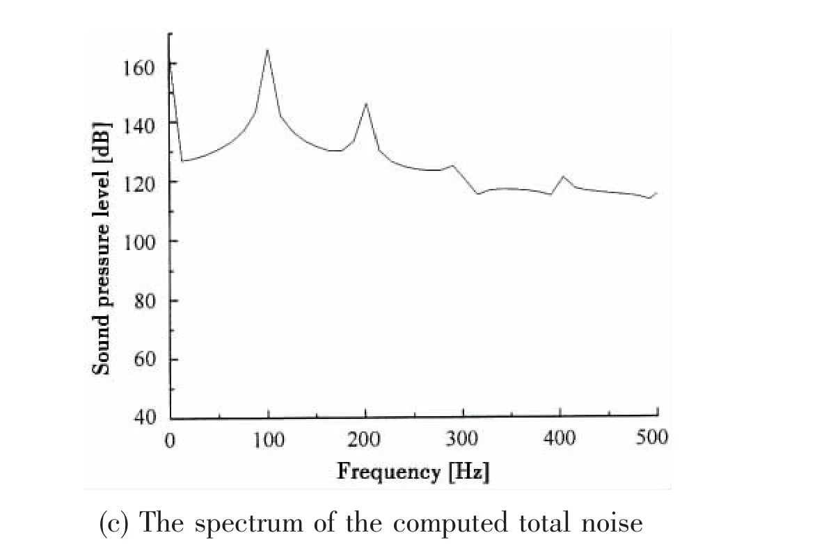
Fig.7 Sound pressure at observer 1
The noise generated by the propeller is predicted at two observers, which were positioned in the propeller disk plane at distances of approximately 0.4 radii and 1.58 radii from the blade tip, respectively.
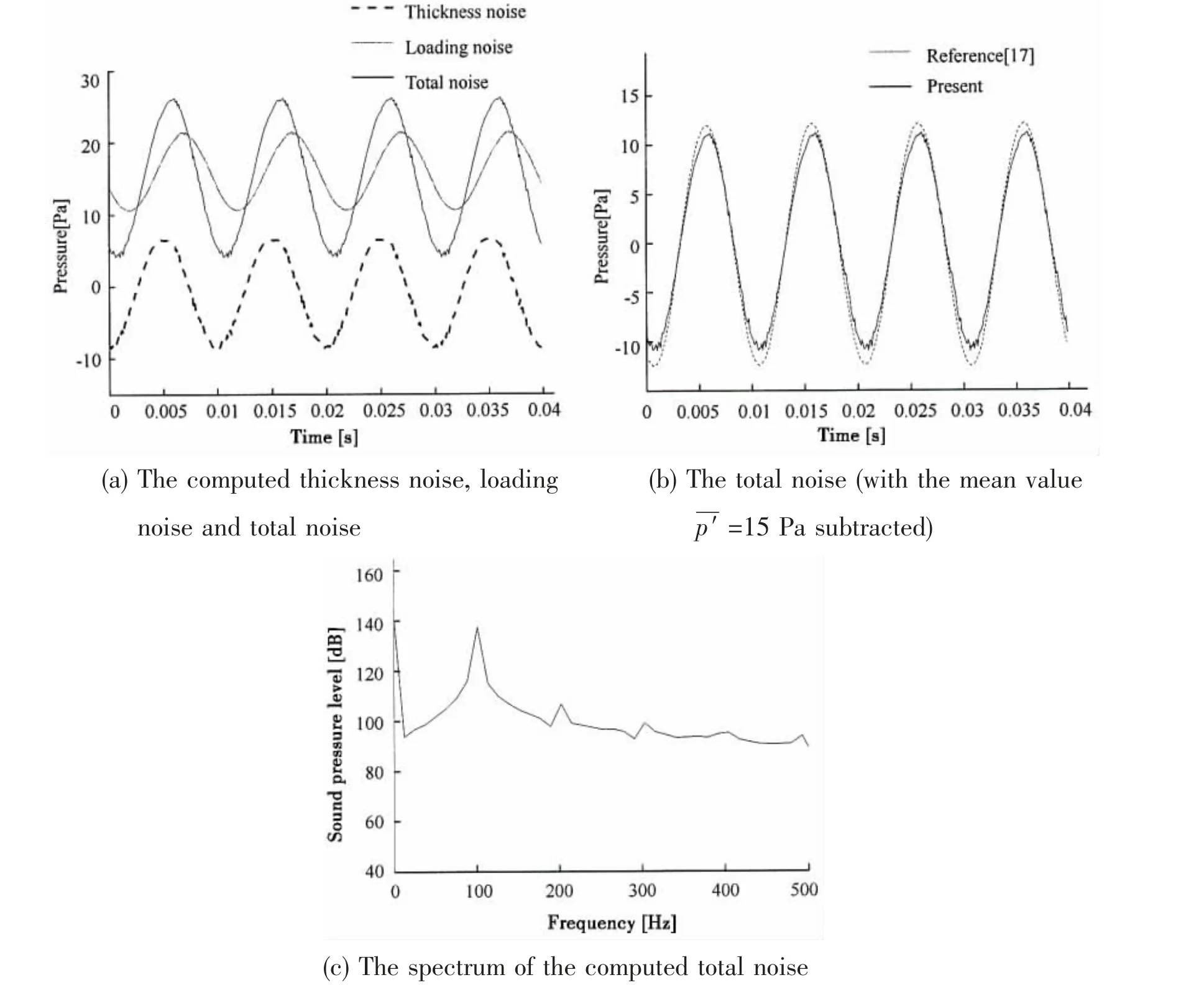
Fig.8 Sound pressure at observer 2
The thickness noise, loading noise and total noise at observer 1 and 2 are shown in Fig.7(a) and Fig.8(a), respectively. The fluctuation amplitudes of thickness noise and loading noise are approximately in the same order of magnitude.
In Fig.7(b) and Fig.8(b), the total noise prediction by present approach is compared with that of Ref.[17]. It is worth noting that for the sake of clarity, the mean value of the noise pressure signals was removed. At observer 1, very close to the blade tip, the pressure time histories predicted by present approach exhibits a perfect agreement with that in Ref.[17], although the pressure peaks were slightly underestimated. Although observer 2 is relatively away from the propeller, the agreement between the present approach and the Ref.[17] also remains satisfactory. It is interesting to note that moving from observer 1 to 2, the amplitude of sound pressure reduced drastically, whereas the distance between the observer 1 and 2 is very limited. There are two reasons which can explain this phenomenon: First, according to the Eq.(2), when the propeller rotates at a fixed speed, the thickness noise only contains the near-field terms. Second, for a propeller operating in uniform flow, the forces on blades are steady in a coordinate system rotating with the propeller. Since the Mach number of an underwater propeller is very low, this steady loading source could not be considered as an efficient acoustic source.
In one revolution period, four peaks appear on the curve of the pressure time histories. It means that the noise waveform is characterized by the BPF (blade passage frequency) of the four-bladed propeller. In Fig.7(c) and Fig.8(c), the propeller noise spectra at observer 1 and 2 are presented. As expected, the noise is dominated by tonal component. The fundamental tone is obvious at BPF (100 Hz), and other tonal noises at higher BPF harmonics (200, 300 Hz...)also appear, but they decrease dramatically as the frequency increases.
5 Conclusions
The ‘source time-dominant algorithm’ was applied to analyse the noise generated from rotating blades in uniform flow. Both the single blade and the four-bladed propeller have been considered. The comparison of the present results with those in reference is very encouraging with an excellent prediction of both the open water performance and the noise signal. The main features of the noise signal are captured:
(1) At the BPF and its multiple frequencies, tonal noise can be observed clearly, that is the so called line spectrum features.
(2) Noise generated from rotating blades in uniform flow decays sharply as the distance between the source and observer increases. Since the rotational speed of the marine propeller is relative slow, the small Mach number leads to a low efficiency of noise radiation of a propeller. Recently, Ianniello[18]demonstrated that the quadrupole source terms in the FW-H equation can not be neglected for a marine propeller. Hence, those non-linear terms will be studied in our future work.
杂志排行
船舶力学的其它文章
- Simulation of Ship Motions Based on the HOBEM Acceleration Potential Method
- Experimental Study on Air Bleed Fusion of Underwater Vehicle
- Numerical Simulation of Cavity and Hydrodynamic Force of the Sphere Water Entry in Consideration of Surface Wettability
- Improved Moving Particle Semi-implicit Method with Large Eddy Simulation for Determining Water-entry Impact and Damage to Flat-bottomed Structures
- A Phase Modification Methodology in Modelling Deterministic Freak Wave Train
- Dynamic Response of Shipbuilding Sandwich Plate System Subjected to Impulsive Loading
