Study on the Affection of Drilling Tools’ Abrasion to the Regular Pattern of Tensile Strength
2019-08-05LIZijie
LI Zijie
[a]Yellow River Drilling Company of Shengli Petroleum Engineering Corporation Limited, Sinopec (SLDTI), Dongying, Shandong, China.
Abstract Drilling tool is a necessary tool in oil drilling engineering,its performance directly affects the penetration rate of drilling engineering, to a well, reasonable selection of drilling tools will be conductive to high-quality, efficient and fast drilling construction. Reasonable optimization of drilling tools, based on the field testing of drilling tools in use, and according to the results of field testing, correctly guide the selection of drilling tools. According to the different drilling conditions, the drilling tools should be reasonably allocated to match the drilling performance with the drilling conditions. Analyze the problems and causes of drilling tools found in testing, and determine the rational solutions and preventive measures. The abrasion and thinning of drilling tools often occurs in the drilling process of oil and gas, which affects the bearing capacity of drilling tools. Tensile load is one of the main load-bearing modes of drilling tools and an important evaluation index of drilling tool safety. By simplifying the drilling tool model, confirm the tensile strength of the wearing drilling tool and the stress state at different well depths, and reach the relationship between the wearing degree of drilling tool and the safe well depth.
Key words: Testing of drilling tools; Oil drilling;Safety of drilling tools; Abrasion and thinning; Tensile strength
In oil and gas drilling, drill pipe is a downhole tool for transmitting torque, applying drill pressure and bearing the weight of drill collar (Dahnel, et al, 2016; Ramirez,et al, 2014). In the process of drilling construction, the abrasion and thinning of drill pipe is affected by scouring action of cuttings (especially in gas drilling), and the contact with borehole wall and casing , which leads to the decrease of its bearing capacity and also buries hidden danger for the occurrence of drill pipe fracture accident. However, abrasion and thinning of drilling tools are allowed in practical engineering, and some abraded drilling pipes can still be used for a long time under certain conditions. Therefore, it is particularly necessary to determine the relationship between the abrasion degree of drilling tools and the bearing capacity.
In many drill pipe fracture accidents, quite a number of accidents are caused by insufficient tensile strength of the drill pipe, especially when slight sticking occurs, the lifting drill tool is very vulnerable to fracture accidents(Samuel Raj & Karunamoorthy, 2019; Samuel Raj &Karunamoorthy, 2018). Therefore, it has strong realistic meaning and engineering value to determine the rational selection and safety use of drill pipes when the tensile strength of worn drill pipes and the stress state at different well depths are confirmed.
1. FIELD TESTING OF DRILLING TOOLS
Drilling tool testing can be divided into two parts: new drill tool testing and old drill tool testing. From the main body of the drill tool, it can be divided into four parts:thread, joint, transition zone and body testing (Arul, et al.,2006; Samuel Raj & Karunamoorthy, 2016). This paper focuses on the testing of used drilling tools.
1.1 Tests of Drilling Tool Thread
Thread accuracy of drilling tools is an important standard to measure the quality of drilling tools (Dahnel, et al,2016), it directly affects the joint strength, sealing and interchangeability of drilling tools.
Thread surface detection: Thread surface is smooth,without burrs, tear, dents, fragmentation and other defects affecting thread strength and connection tightness.
Thread taper detection: put cone gauge on the cone of thread, and then use feeler to measure the gap between conical surface of cone gauge and cone surface of thread;if the gap is large, the thread taper error will be large, and vice versa.
Thread ellipticity detection: There are two commonly used methods. One is radial measurement method, which directly measures the maximum clearance between taper surface of taper gauge and taper surface of thread tip at 180 degrees; the other is axial measurement method,which calculates the ellipticity error of thread by measuring the axial displacement value of taper gauge.
Measuring thread tightness: After the thread gauge and the detected thread are screwed together, the distance between the end face of the thread gauge and the vanishing point of the tested male thread or the end face of the nut thread (i.e. the upper tightness) is measured with a measuring tool; if the working accuracy is high,the upper tightness is equal to or close to the prescribed value, such products are qualified products, otherwise, the processed products are inferior or non-qualified products.
1.2 Tests of Drilling Tool Joint
The joints of used drilling tools are deformed due to wear and tear. There are three main deformed features:
First one is that when the drill tool rotates downhole,it rubs against the inner wall of the casing or the borehole wall, resulting in the wear of the outer surface of the joint,which is usually detected by calipers. Second one is that in the process of drilling, the drilling tool does not rotate and only feeds axially, such as directional drilling and horizontal drilling driven by downhole power drilling tools. In this case, the outer surface of the drill tool joint slides with the inner wall of the casing or the borehole wall, and the outside diameter of the joint is in a nonuniform wear state, which results in the eccentric wear of the diameter dimension in the circumferential direction of the outer surface of the joint. In addition to measuring the uneven outer diameter of the joint, the eccentric wear degree of the outside diameter of the joint should also be emphatically measured. Last one is the axial wear of drill tool joints, such as grinding shoulder, truck shoulder and thread processing. The length becomes shorter.Generally, the axial length of the joints is only measured by steel plate ruler, which is qualified when it is larger than the prescribed value, and when it is smaller than the prescribed value, the well feeding is stopped.
1.3 Tests of Drilling Tool Transition Zone
The transition zone of drilling tool is the weakest link of drilling tool. It is the joint of larger inner diameter of drilling tool body and smaller inner diameter of joint body. Its length is generally about 10 centimeters.Generally, combining measurement with flaw detection to test it. When measuring, the instrument for measuring the thickness of steel parts is used to measure the distribution of points. If there is no obvious change in wall thickness,it will be qualified. When individual pits are serious, it will be regarded as unqualified drilling tools or abandoned drilling tools. In flaw detection, it is mainly to detect whether there are internal cracks or fatigue scars in the transitional zone of drilling tools. To meet the required requirements is qualified, otherwise it is unqualified.
1.4 Tests of Drilling Tool Body
Inspection of the outside dimension of the tube body: The outside diameter measuring tool and the length measuring tool are qualified within the prescribed value, otherwise they are not qualified.
Inspection of internal damage in pipe body: The length of drilling tool usage time and the depth of well used are generally stipulated as the basis of internal injury inspection. Using drill tool testing equipment, the pipe body is inspected to determine the extent of the damage.If the damage of the pipe body is within the allowable range, it can continue to be used in wells, otherwise it will be degraded or abandoned.
Detection of pipe wall thickness: Use steel thickness measuring instrument to measure the thickness of the pipe,record the change value of pipe wall thickness, or use drill tool comprehensive detector to detect the thickness of the pipe.
1.5 Analysis of Drilling Tool Test Results
1.5.1 Analysis of Test Results of Drilling Tool Joints
Two results are given by testing: one is that it can still be used; the other is that it is not allowed to re-enter the well,which can be subdivided into temporary and perpetual.See Figure1: Test results of drilling tool joints.

Figure 1 Test result chart of drilling tool joints
Permanent prohibition of well entry means that it must be abandoned. This kind of wear is not expected in the test results of drill tool joints, but it is inevitable.
Reasons for Joint Scrap
According to the analysis of test results, there are three reasons for the scrap of drill tool joints:
a. There is injury inside the joint and the degree of injury exceeds the prescribed value.
b. The radial wear of the joint reduces the geometric size and is less than the prescribed value.
c. The axial wear of the joint reduces the geometric size and is less than the prescribed value.
(2) Precautions
Based on the analysis of the above reasons and combined with the field application, the following measures can be taken to effectively prevent the abrasion of drill tool joints:
a. The external surface of the joint improves strength and wear resistance. In this respect, spraying or welding cemented carbide wear-resistant belt can be adopted on the outer surface of the joint, and the outside diameter of the joint is slightly larger than that of the joint.
b. Surface treatment of joint threads. There are two effective ways. One is to use parkerising treatment to form a very thin phosphate film on the thread surface.This phosphate film can store a certain amount of lubricating oil in the tiny holes. It can change the contact condition and stress state of the thread surface, so that the thread surface can be protected under various stresses and corrosion. The other method is to use copper plating treatment on the thread surface to form a very thin copper film. This copper film has excellent anti-corrosion and anti-bonding effect, so that the thread surface can be effectively protected under various stresses and corrosion.
c. Drilling tool joint flaw detection. Flaw detection cannot directly protect the joint of drilling tools, but it can detect the damage of the internal structure of the joint at an early stage. One aspect is to inspect the joints of drilling tools, and the other aspect is to inspect the threads of the drilling tools joints.
1.5.2 Analysis of Test Results of Drilling Tool Body
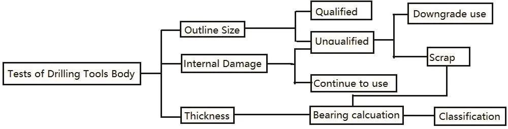
Figure 2 Test result chart of drilling tools body
As can be seen from Figure 2, pipe inspection is very important, and the results will effectively guide the rational use of drilling tools and prevent blind downhole.
Reasons for tube scrap
According to the analysis of testing results of drill pipe, there are three reasons for the scrap of drill pipe.
a. Internal injury in the tube, and the degree of injury exceeded the prescribed value.
b. The shape and size of the tube body vary greatly and exceed the scope of application.
c. The wall thickness of the tube decreases, and the bearing capacity of the tube is lower than the prescribed value.
(2) Precautions
a. High quality drilling tools are used to improve the strength of the pipe body. The use of steel with good quality and performance is the basis to prevent the failure of drill pipe.
b. Actively promote the application of coating technology in drill pipe body. The high pressure, high speed flow and corrosion of drilling fluid are the main causes of abrasion and damage to the inner wall of drilling pipe. The technology of coating inside drilling pipe is a direct and effective way to solve this contradiction(Ramirez, et al, 2014; Samuel Raj & Karunamoorthy,2019).
c. Tube flaw detection. Early detection of pipe injury can guide the correct and rational use of drilling tools in production and avoid the rapid expansion of pipe injury.If the pipe injury is serious, timely measures can be taken to effectively avoid the huge economic losses caused by downhole drilling accident to the drilling team.
2. CALCULATIONS OF MODELS AND RESULTS
In the process of drilling, the abrasion and corrosion of drilling tools are very serious, which eventually leads to the decrease of the wall thickness of drilling tool and the decrease of bearing capacity until the drilling tools become invalid or scrapped. After the drilling tool enters the well, it mainly bears the tension and the buoyancy of the drilling fluid without applying the drilling pressure.After adding drilling pressure, the upper drilling tool bears tension and drilling fluid buoyancy, while the lower drilling tool bears pressure and drilling fluid buoyancy. In general, the drill collar is at the bottom of the wellbore to exert drill pressure on the bit, and the drill pipe is at the top of the wellbore to bear the suspension weight of the whole drill string. Moreover, when the drill pressure is zero, the pulling force of the wellhead drilling tool is the largest.
2.1 Hypothesis of Models and Materials
It is difficult to analyze the drill pipe in the well completely according to the actual situation. In order to simplify the problem and highlight the main factors,the following assumptions are made for the geometric structure and material of the defective drill pipe.
• The abrasion of the drill pipe is a local defect, so the stress concentration will occur at the defect under the loading condition. However, the wear of the drill pipe is generally uniform wear with a larger area and a smaller stress concentration, which should not be considered.
• The drill pipe material is uniform and ideal elasticplastic material, and the change of cross-sectional area is not considered in stretching.
2.2 Tensile Forces on Drill Pipes of Different Depths
A well with a depth of, the drilling tool goes down to the bottom of the well. There are drill collars under the cross section of the drill pipe at Lxfrom the ground. The length of each drill collar is L, and the weight of each drill collar is G1. There are drill pipes, and the weight of each drill pipe is G2. So it is available that:
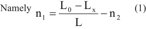
The weight of the collar and drill pipe below the cross section of the drill pipe at Lxfrom the ground is as follows:

From Formula (1) and Formula (2):

The pulling force on the cross section of the drill pipe at Lxis equal to the weight of the lower collar and the drill pipe Gxminus the buoyancy B of the drilling fluid on the whole drilling tool in the well. So,
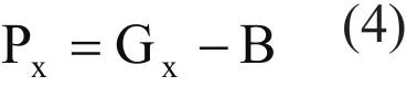
Buoyancy of Drilling Fluid on Drilling Tool in Well:
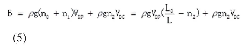
In the formula: VDPand VDC——The volume of each drill pipe and collar respectively.
From Formula (3), Formula (4), Formula (5)

from formula (6):

Formula (7) is about the pulling force on the cross section of the drill pipe at Lxfrom the ground.
2.3 Limit Tensile Force of Thinned Section
OD of drill pipe is Ф,Thickness is δ,Wear thickness is Tx,Cross-sectional area is Sx:

From formula (8) and (9):
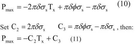
Formula (11) is ultimate Tensile Force of Wear Section.
2.4 Safety Depth of Thinning Section in Well
The tension Pxof the drill pipe at different depths and the ultimate tension Pmaxat the wear point are calculated above. In order to prevent drill pipe from breaking, it is necessary to satisfy that the pulling force Pxof drill pipe at wear site is less than the ultimate pulling force Pmax. as:
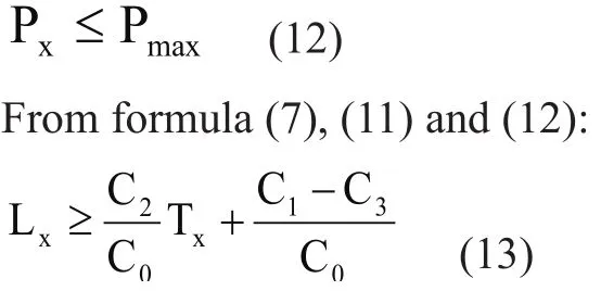
Formula(13)is the relation formula of safety depth of drill pipe in well with wear thickness Tx。The depth of drill pipe in well with wear thickness Txshould be deeper
2.5 Suitable Well Depth for Wellhead Abrasion Drill Pipe
When wear occurs at wellhead position (As Lx=0), drill pipe bears the greatest load, so it is necessary to find out the relationship between the wear thickness and the safe well depth.
When Lx=0,we know from formula (6) that:

From formula (11), (12) and (15), we can know that:

Formula (16) is about the relationship of wellhead drill pipe with wear thickness Txand suitable safety well depth.The formula requires that wellhead drill pipes with wear thickness of Txshould be used in wells with a depth of not
3. EXAMPLE ANALYSIS
Reasonable selection of drilling tools is a very important work in drilling engineering. Proper selection can not only ensure the safety of drilling construction, give full play to the best advantages of drilling tools, but also reduce downhole drilling accidents and drilling costs. The improper selection will result in waste of drilling tools or complex downhole, increase drilling cost, and even scrap drilling engineering. Therefore, after the determination of drilling engineering design, according to the relevant parameters of engineering design, drilling tools should be reasonably equipped to avoid blindness. Taking drilling tool assembly commonly used in Zhongyuan Oilfield as an example “Φ158.8mmDC×18 + Φ127mmDP + Kelly”(Samuel Raj & Karunamoorthy, 2018; Arul, et al, 2006)(Samuel Raj & Karunamoorthy, 2018; Arul, et al, 2006),evaluate the safety of drilling tools.
3.1 Relevant Technical Parameters
According to statistics, the density of drilling fluid in different sections of Zhongyuan Oilfield is shown in Table 1.

Table 1 Interval Density Table
Technical data of drilling tools (Samuel Raj &Karunamoorthy, 2016):
(1) Φ158.8mm DC: Length 9.15 m,ID 71.44 mm,Unit weight 124.5 kg/m。
(2) Φ127mm DP: nominal weight 29.0 kg/m。
3.2 Φ127mm×G105×9.19 DriII Pipe
Based on formula (16), the calculation results of drill pipeΦ127mm×G105×9.19 are shown in Table 2.
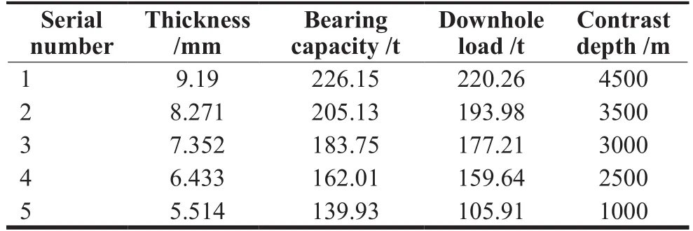
Table 2 G105 Drilling Tool Load Contrast Judgment Table
Table 2 shows that new drilling tools of Φ127mm×G105×9.19 can drill to 4500m. When the wall thickness is reduced to 90%, it can only be used in 3500m wells. When the wall thickness is reduced to 80%, it can only be used in 3000m wells. When the wall thickness is reduced to 70%, it can only be safety used in 2500m wells. When the wall thickness is reduced to 60%, it can only be safety used in 1000m wells.
3.3 Φ127mm×S135×9.19 DriIIing TooI
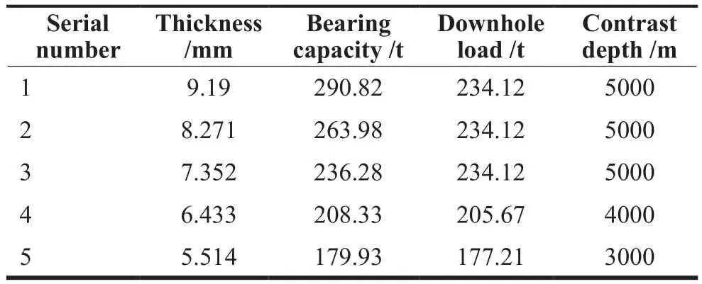
Table 3 S135 Drilling Tool Load Contrast Judgment Table
Table 3 shows that when the wall thickness of drilling tools of Φ127mm×S135×9.19 is reduced to 80%, it can be used in 5000m depth wells. When the wall thickness is reduced to 70%, it can only be safety used in 4000m wells. When the wall thickness is reduced to 60%, it can only be safety used in 3000m wells.
CONCLUSION
(1) In the process of drilling construction, wear and thinning of drill pipe often occurs.
(2) The depth of drill pipe in well with wear thickness
(3) Wellhead drill pipes with wear thickness of Txshould be used in wells with a depth of not more

杂志排行

Advances in Petroleum Exploration and Development的其它文章
- Staged Premium Screen Completion Design for Horizontal Well Based on Laboratory Test: A Successful Application in Block 451, Shengli Oil Field
- Simulated Calculation of Bullheading Method When the Well is Empty
- Development of Organic Soil Suitable for Biodiesel-Based Drilling Fluids
- Optimization Program for Difficult-to-Produce Reservoir in Bonan Oil Feild
- Producibility Scenario of Unidentified Productive Zone
- A Drilling Liquid to Reduce the Damage Coalbed Methane