Anti-collision Optimization Design Technology of Large Infill Cluster Well Group in Bohai Sea Artificial Island B
2019-08-04XUWenhao
XU Wenhao
[a] Drilling Technology Research Institute of Shengli Petroleum Engineering Corporation Limited. Sinopec (SLDTI), Dongying,Shandong, China.
Abstract In view of the difficulty and low efficiency in the design of collision prevention and obstacle avoidance in the large-scale infilling adjustment of the cluster well group in Bohai Sea artificial island B, based on the analysis of the overall situation and characteristics of the infilling well,accurate calibration of already drilled data, and using industry standard principles for cluster well platform optimization and anti-collision design, develop specific procedures for designing anti-collision tracks for large-scale infill wells, form anti-collision optimization design methods,optimize drilling sequence, slot matching relationship and anti-collision track design parameters.The track design and anti-collision analysis of 45 infill wells have been completed in the limited platform space through multiple slot adjustment and track optimization.The minimum value of the separation coefficient of each well meets the requirements of the industry standard minimum limit of 1.5, and 70% of them are concentrated above 1.7, which reduces the risk of anti-collision as a whole.The results show that the anti-collision optimization design technology of large-scale infill cluster well group can effectively solve the anti-collision design problem of large-scale infill adjustment of cluster well group, and help to improve the design quality and efficiency.
Key words: Infill well; Cluster well group; Anti-collision; Slot optimization; Drilling sequence optimization; Track design
At the middle and later stage of development, the oil recovery rate of some offshore oilfields has declined significantly, especially the production of offshore heavy oil steam stimulation development is declining rapidly and the recovery factor is low. In view of this situation, it is of great technical and economic significance to make full use of the existing platform resources for offshore cluster well cluster infilling adjustment. At present, the well platform optimization and anti-collision technology of large cluster well group is relatively mature, and industry standards and recommended practices have been formed. However, the infill adjustment of large offshore cluster well groups generally involves a small number of wells, mainly the optimization of single wells. If large-scale infill adjustment is performed within the same platform or large cluster-type well group, the well pattern is dense,the underground space is occupied seriously, and the collision prevention optimization problem between infill wells and already drilled and infill wells exists. The involved slot optimization and anti-collision track design technology is complicated, the anti-collision risk and the optimization difficulty are greater, which are currently less applied at home and abroad. Therefore, it is urgent to form a set of anti-collision optimization design method suitable for large-scale infill cluster well cluster, so as to improve the efficiency and quality of well cluster optimization and track design. Based on the analysis of the anti-collision situation of infill wells in Bohai artificial island B , this paper studies the data verification technology, the overall optimization technology of well platform and the design technology of anti-collision track, forming the optimization design method of anti-collision and bypass of large infill wells, successfully completing the anti-collision analysis and track design of 45 infill wells in Island B , and the design track meets the requirements of industry standards. (State Energy Administration, 2015)
1. GENERAL SITUATION OF LARGE CLUSTER WELL GROUP IN ISLAND B
1.1 Well Group Survey
Heavy oil steam huff and puff method is adopted in the development of artificial island B in Bohai Sea. Due to the imperfection of well pattern and excessive well spacing in some areas, the effect of thermal recovery and development is affected. Meanwhile, restricted by the economic and environmental protection requirements of the project, it is impossible to build a new drilling platform. Therefore, it is proposed to further improve the underground well pattern by adding 45 infill wells. Among them, 8 horizontal wells are designed, others are highly deviated directional wells. Island B has been drilled as L-shaped well row and infill wells as straight-line well row. After infilling, the total number of wells in the artificial island reaches 115. Prior to the implementation of the project, it is necessary to optimize the design of infill well track and demonstrate its feasibility.
The slot of infill well row of island B is parallel to the longitudinal slot of L-shaped well row of the original platform, with a spacing of 13.5m, as shown in Figure 1.The infill well slot is divided into 9 small well groups from north to south.
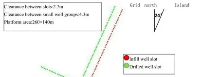
Figure 1: Distribution of infill wells and drilled slots
1.2 Overall Anti-Collision Situation
More than 30 geological targets are arranged in the northwest of the L-shaped well row on the original platform of Island B. The vertical section of a tandem well in a well row is similar to a "fence" shape, and some wells have deeper deflection points. In order to complete the design of the target in the infill well, it is necessary to cross the track from the bottom of the "fence".
In the same depth reservoir developed by infill wells and drilled wells, the displacement of each infill well target point is different from that of the drilled target point, the vertical depth is basically the same, and they are all concentrated in one direction (northwest direction).In order to complete the target design of these geological targets, there will be a large number of anti-collision points between the designed trajectory and the drilled trajectory. In addition, the dense targets in the northwest region will cause limited space for orientation adjustment on the horizontal plane, and it is difficult to prevent collision and bypass the obstacles.
Due to the deviation or predirection of the drilled vertical well section, the underground space of the infilled well slot is occupied seriously, and the main occupied well section is concentrated in the range of 350-700m, that is, the vertical well section or directional deviation section of the infilled well, the shallow layer collision prevention problem is prominent, and some infilled wells need to be bypassed in a predetermined direction.
2. ACCURACY CALIBRATION OF DRILLED WELL TRAJECTORY DATA
In the design of anti-collision track for cluster well cluster infill wells, there are generally problems that the calculation environment of the drilled track and infill well design track software is inconsistent. The design of infill well cluster is different from the coordinate system, track calculation method, geomagnetic model system and well depth datum used in the construction of the drilled well cluster. It is necessary to unify and calibrate the track data of the old well accurately. (Liu, Shi, & Li, 2012)
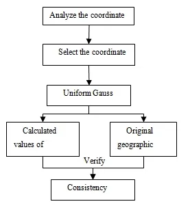
Figure 2: Flow chart of coordinate system calibration method
The relative position and distance of wellhead, target and anti-collision point are the basis of anti-collision design. The relative position and distance of two points on the earth can be determined by geographical coordinates and vertical depth of position. The geographical coordinates calculated by the same ellipsoid model are consistent. The calibration software is mainly used to unify the ellipsoid model. On this basis, the Gauss projection coordinates are calibrated, and then the geographical coordinates of the drilled wellhead and target point are recalculated according to the projection coordinates. Check whether the geographical coordinate calculation results of each well are the same as the geographical coordinate values provided by the construction company, verify the accuracy of the track data, and complete the calibration of the coordinate system. The calibration method of the coordinate system is shown in Figure 2. By using the same "Krasovski" earth ellipsoid model as the drilling trajectory calculation model, the transformation from Beijing_1954 to Gauss Kruger(Pulkovo 1942) coordinate system has been completed.
The minimum curvature method is adopted for the orbit calculation of Island b, and the well depth datum is unified to the sea level. Since the north grid position angle is adopted for the drilled data, the geomagnetic system has no direct impact on the orbit design of the infill well. Otherwise, it is necessary to modify and calibrate the magnetic deviation angle according to the geomagnetic model used in the construction.Using the above well trajectory calibration method, the accuracy of the trajectory data of 70 wells has been calibrated. The trajectory parameters calculated by the software during the calibration process are consistent with the data provided by the drilling construction company, which verifies the validity of the data.
3. OPTIMIZATION DESIGN TECHNOLOGY FOR PREVENTING COLLISION AND OBSTACLE AROUND OF LARGE INFILL CLUSTER WELL GROUP
3.1 Optimization Design Process of Collision Prevention and Obstacle Avoidance
Different from the situation of new well platform or a small number of infilling wells, the optimization of anti-collision and obstacle avoidance of large infilling cluster well group in Island B involves two well groups,which not only meets the requirements of internal slot, drilling sequence optimization and collision avoidance of infilling well group, but also carries out anti-collision and obstacle avoidance with old well group, which is difficult to optimize.In order to avoid repeated adjustment of some well tracks, a reasonable design process must be defined, and the specific implementation process of optimization design is shown in Figure 3.
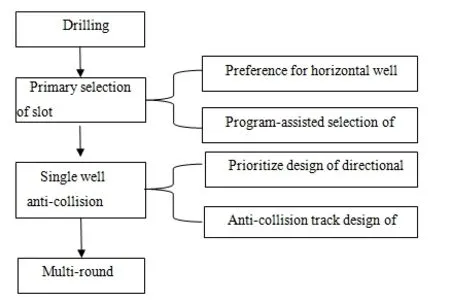
Figure 3: Flowchart of anti-collision optimal design for infill well group
The horizontal well needs to be twisted to the target frame to reach the target. In order to avoid excessive curvature of the well caused by large-scale torsion, the horizontal well should be given priority in slot distribution(Han, et al, 2014; Dogru, 1987; Zhou, et al, 2012; LIU, et al, 2016); the directional well orbit orientation changes little,and there are relatively few anti-collision wells involved in anti-collision, so the directional well orbit circling is given priority, which can improve the serious phenomenon of orbit horizontal projection crossing in the early design.Applying this flow to the design can effectively improve the efficiency of the design. (Wu & Sharma,2016)
3.2 Drilling Sequence Optimization
In the construction of Island b, the electric modular drilling rig is adopted, which is constructed in the form of large cluster well group drilling. During the first construction waiting for setting, the whole drilling rig is towed to other slotes for cross operation, which improves the overall construction efficiency of cluster well. The intensive well row of Island B adopts the linear well row slot optimization method. The rig's entire drag requires staggering the depth of each well. Wells with large displacement and shallow deflection point and wells with small displacement and deep deflection point adopt the staggered construction method to eliminate the influence of magnetic interference of the inclinometer and increase the shallow anti-collision well spacing. At the same time,the construction of the inclined points in the small well group is ensured from shallow to deep. The infill well drilling sequence is shown in Figure 4.
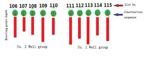
Figure 4: Drilling sequence
The advantages of this drilling sequence optimization method are high flexibility of construction operation, on the one hand, it can improve the overall construction efficiency, which is conducive to the overall planning and design of collision prevention and obstacle avoidance; on the other hand, in case of special circumstances during construction, it is necessary to adjust the slot construction sequence, which can be adjusted between adjacent well groups when the deviation point of small well groups is from shallow to deep.
3.3 Slot Optimization
3.3.1 Slot Optimization Method
The factors involved in slot optimization of large-scale infill cluster well group are complex, which are mainly affected by factors such as closing distance of target point, closing direction, slot layout shape, anti-collision and obstacle around, etc. (Zhang, et al, 2010) at the same time, it is also necessary to consider reducing workload and construction difficulty. Slot optimization is actually the optimization problem under the influence of many factors.Before optimization, we need to simplify the treatment, ignore the impact of the anti-collision of the drilled wells,only consider the optimization of the groove inside the infill well row, and use the groove optimization method of the new well row to preliminarily optimize the groove.
According to the principle of anti-collision optimization design for large dense cluster well group (State Energy Administration, 2015), the horizontal well slot is preferred. The primary selection of horizontal well slot is based on the principle of minimum trajectory control workload. Due to the limitation of displacement in front of the target,the workload of trajectory control is less affected by the rate of well deviation change, and the main influencing factor is the torsional azimuth. After the slot is preliminarily selected, adjust the slot according to the impact of anti-collision. (Wilson, 2016)
The primary selection of directional well slot needs to meet the requirements that the horizontal projection of each well track in the infill well array is not intersected, so as to avoid a large number of intersections between infill wells, drilled wells and infill wells in the later stage of collision prevention and obstacle avoidance(Manchanda, et al., 2016), which is conducive to reducing the difficulty of collision prevention design and workload.
3.3.2 Slot Optimization of Horizontal Well Based on Minimum Workload
As shown in Figure 5, the extension line of the target line to the wellhead is called the design azimuth line. The distance between the point projected from the wellhead to the design azimuth line and the wellhead is the vertical distance, which is the displacement that must be completed when the trajectory is adjusted to the final target frame orientation. It can also be called the deviation of the wellhead from the design azimuth line. The length of the distance is positively related to the workload of torsion azimuth.
According to the target setting principle of horizontal well, the target line orientation of horizontal well is radially distributed relative to the platform center, and the target setting of horizontal well is completed. Due to the difference of vertical distance between each slot position of infill well row and the connection direction of horizontal well target point, it is considered to reduce the workload of trajectory adjustment. It is necessary to optimize and adjust the slot of the whole well group to minimize the sum of vertical distance of the whole platform horizontal well and complete the preliminary optimization of the slot.
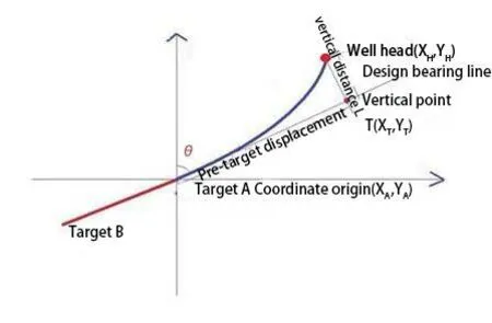
Figure 5: Diagrammatic sketch of vertical distance from well head to design azimuth line
Set target A as the origin of coordinate, the extension part of the connection between target A and target B as the design azimuth line, and the vertical projection from the wellhead to the design azimuth line is the vertical point T.the geodetic coordinate of the vertical point can be derived from the known geodetic coordinate of target A, and the distance from the well head to the vertical point can be calculated according to the coordinate value and the wellhead coordinate, that is, the vertical distance.
1) Calculate the vertical point coordinate with known target A geodetic coordinate
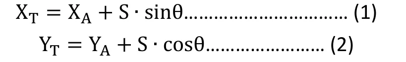
In where, XTis the abscissa of the vertical point, m; YTis the vertical coordinate of the vertical point, m; XAis the abscissa of target a, m; YAis the longitudinal coordinate of target a, m;θis the closing azimuth angle of target a and vertical point, °;Sis the pre-target displacement, m.
2) Calculate the vertical distance according to the vertical point coordinate and the wellhead coordinate
Where,Lis the vertical distance, m; YHis the vertical coordinate of the wellhead, m; XHis the horizontal coordinate of the wellhead, M.
Taking the minimum amount of work in torsional direction as the goal, and adjusting the slot to minimize the sum of calculated vertical distance, the preliminary selection of the slot of horizontal well is completed, and the results are shown in Figure 6 and Table 1.
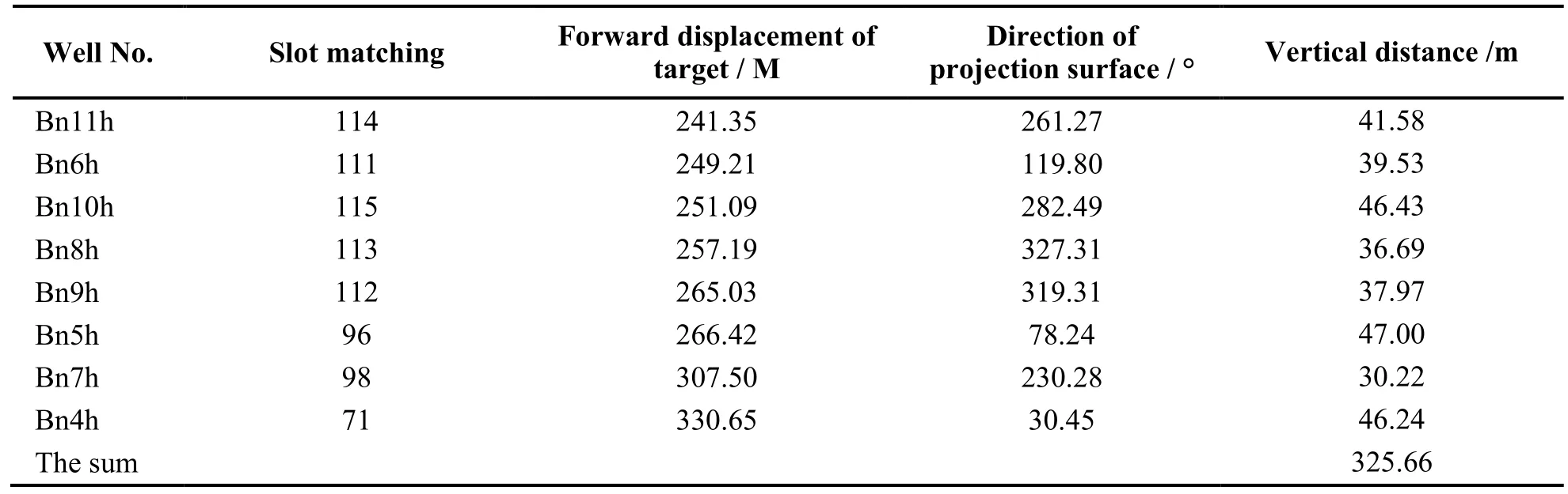
Table 1 Optimization results of horizontal well slots distribution
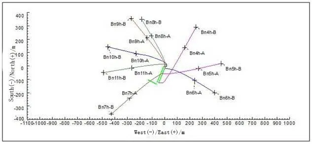
Figure 6: Optimization results of horizontal well slot
3.3.3 Optimization of Directional Well Slot Based on Program Aided Design
In case a new well array is built for a large cluster well group, and the density of well array and the number of wells arranged are not large, the design workload is small, and the corresponding relationship between slot and target point is relatively intuitive, so manual adjustment can be used to optimize slot. Island B has a complex drilling and anti-collision situation, with a large number of infill wells. Considering the geological target to slot orientation, closure distance, anti-collision requirements and other factors, the design workload and optimization are difficult. Therefore, the slot is optimized in the way of Landmark program assisted with manual adjustment.The program can automatically optimize the slot according to the distance and orientation from the slot to the target point, so as to minimize the total displacement, but it can not consider the impact of anti-collision between infill wells, so it is necessary to manually adjust the specific anti-collision conditions of individual infill wells.
On the basis of the result of slot optimization of Landmark program, according to the principle of no crossing of horizontal projection of directional well track, the slot of each well is adjusted manually according to the relative position relationship and distance between the target point and the slot, so that the well tracks are distributed radially.The adjustment result is shown in Figure 7, and the slot adjustment of 20 wells has been completed. After adjustment, the horizontal projection of all directional well design tracks has no intersection.
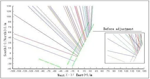
Figure 7: Slot adjustment of directional well
3.4 Design of Three-Dimensional Anti-Collision Track
Due to the limitation of the space position and orientation of the target point, the obstacle avoidance and the different requirements of the technology, it is necessary to design a reasonable three-dimensional orbit under multiple constraints. In order to reduce the difficulty of drilling and meet the requirements of production operation,the track design of directional well and horizontal well requires the build-up slopes of 3.5 ° / 30 m and 4.5 ° / 30 m respectively, and the stable angle of directional well is less than 65 °. Based on the analysis of the safe obstacle avoidance space, several ideal track path positions are set as the self-designed target area, and the track simulation is carried out by using the track design software, so that the designed track can pass through the self-designed target area according to the required build slope middle target, the horizontal well requires the geometric middle target, and if it can not meet the requirements, the slot needs to be adjusted before the track design.
3.5 Multiple Slot Adjustment
The well pattern of island B is dense, and the anti-collision effect of drilled wells is not considered in the process of slot optimization. According to the result of preliminary selection of slot, some wells can not complete the anti-collision barrier, so it is necessary to adjust the slot in multiple rounds to maximize the number of wells designed for anti-collision track of infill wells.
The implementation steps of slot adjustment are as follows:
1) Avoid crossing of track projections. For horizontal wells that cannot be bypassed due to horizontal projection intersection of tracks, horizontal projection intersection of tracks shall be avoided by exchanging slots, and then the design of bypassing barriers shall be carried out, such as wells bn6h and bn5h;
2) Avoid dense well sections. Because the closed azimuth direction of the target passes through many drilled wells, and the depth of the anti-collision point is deep, and the adjustment range of the orbit around the obstacle is too large, the way of adjusting the slot can be used to change the closed azimuth direction, such as B65, Bn9h,B83 and other wells;
3) Adjust the build-up point. It is difficult to stagger the well with enough distance at the deviation point of the small well cluster. It can be inserted into a shallow well at an interval to improve the anti-collision and obstacle avoidance space of the whole small well cluster, such as the setting of B90 well slot;
4) The well with anti-collision interference shall be adjusted as a whole. Adjusting the slot of a well may lead to the change of the anti-collision situation of multiple wells, which requires overall slot adjustment and track anti-collision design, such as well Bn7h.
As shown in Table 2, after multiple times of slot adjustment and track optimization, the problem that six wells can not be bypassed is solved, the overall anti-collision difficulty of one small well group is reduced, and the separation coefficient of some wells is increased.
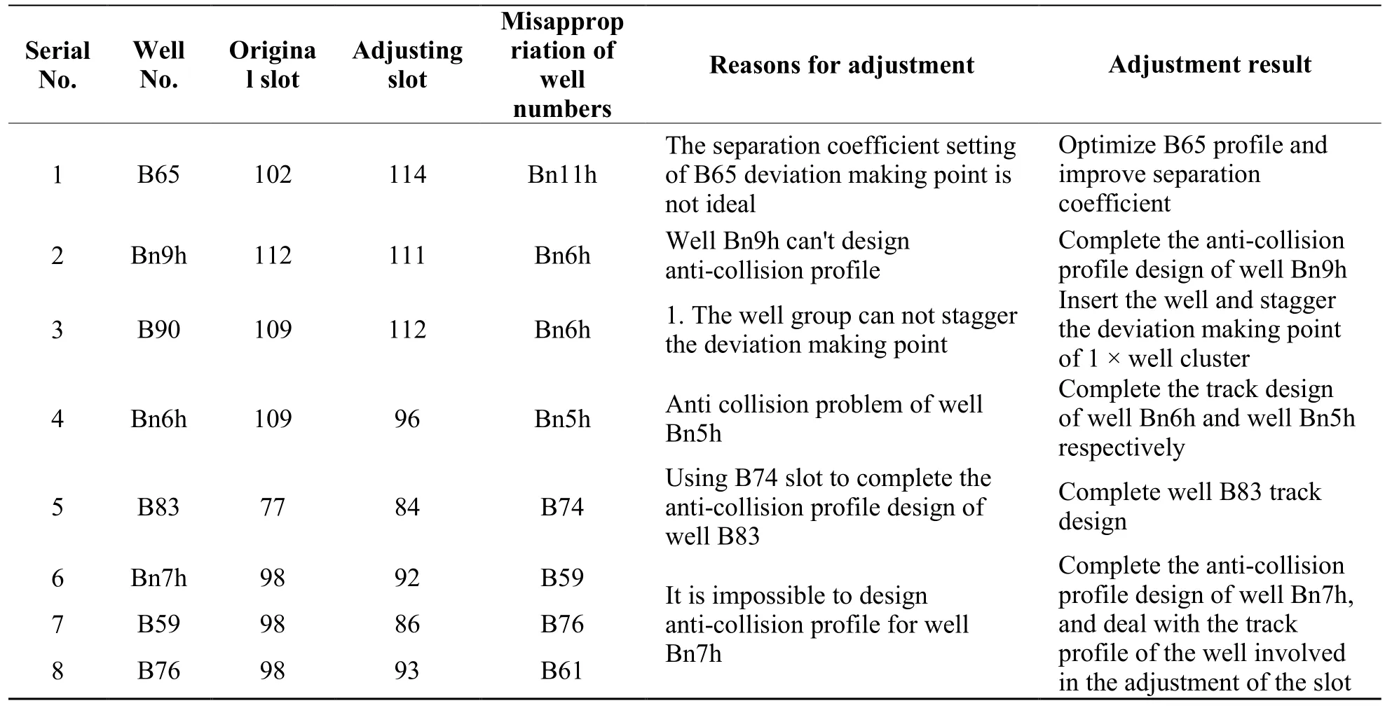
Table 2 Slot adjustment results
3.6 Optimization Design Results of Anti-Collision and Obstacle Avoidance
Using the technology of anti-collision optimization design of large-scale infill cluster well group, the anti-collision design of 45 infill wells has been completed. The anti-collision scanning results of each well meet the requirements of industry standards: the separation coefficient is greater than 1.5 or the nearest distance of anti-collision is greater than 15 m (State Energy Administration, 2015). The nearest distance method is used to conduct anti-collision scanning for all infill wells with a scanning radius of 15m. The scanning results show that the number of anti-collision wells with a separation coefficient of less than 2.0 is generally less than 4, and the lowest value of the separation coefficient of each well is more than 1.7, which reduces the risk of anti-collision as a whole. For each well corresponding to slot 71~115, the minimum value of separation coefficient and the number distribution of anti-collision wells in anti-collision scanning are shown in Figure 8.
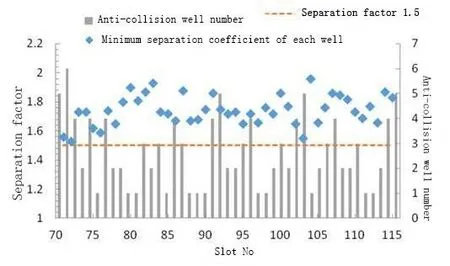
Figure 8: Scanning results of design track anti-collision
CONCLUSIONS AND SUGGESTIONS
1) In the anti-collision optimization design of large-scale infill cluster well group, it is very important to calibrate the drilling trajectory and position accurately, complete the conversion between different coordinate systems and geomagnetic models, and determine the unified well depth datum and trajectory calculation method,which is especially important for infill adjustment wells with long construction time or large difference in trajectory calculation software.
2) The anti-collision optimization technology of large-scale cluster well group is the key technology of large-scale infilling adjustment of large-scale cluster well group. The principles, methods and technologies involved in drilling sequence optimization, slot optimization and adjustment, and anti-collision track design of the cluster well group are helpful to improve the design efficiency of the cluster well group.
3) For the infill wells with different slot layout, this optimization method can be used to deal with the interference between well groups systematically and efficiently.
杂志排行

Advances in Petroleum Exploration and Development的其它文章
- Research and Field Application of Casing Return Well Treatment Technology in Fuyu Oil Field
- Modular Frame Method Plugging in Fuyu Problem Well for Treatment Application
- Technical Difficulties and Countermeasures of Drilling ofΦ118mm Sidetracking Horizontal Well in Changqing Oilfield
- Five-Section Trajectory Design of Thick Glutenite Reservoir in Shengli Oilfield
- Design and Experimental Study of Non-contact Power Transmission Device in Static Push-type Rotary Steering Drilling System
- Prediction Study of Niger-Delta Brown Fields Using Simulation Horizontal Wells Technology