Design Philosophy of Metacomposite Materials Based on Functional Fibers
2019-06-11FaxiangQinDianaEstevezeHuaXinPeng
Faxiang Qin, Diana Esteveze,Hua-Xin Peng
(Institute for Composites Science Innovation(InCSI), School of Materials Science and Engineering,Zhejiang University, Hangzhou 310027, China)
Abstract:Recently,metamaterials attract much attention due to a number of possible applications including those for microwave range, perfect lenses and electromagnetic cloaking.Conventionally, a metamaterial is considered to consist of metal wires and metal split rings assembled in a periodic cell structure.However,such design suffers from too small dimensions and is not suitable for cases when the objects made of metamaterial aim for large-scale applications.In this review,we will show a particular type of metamaterials, named as metacomposites, i.e., fiber reinforced composite material with the metamaterial characteristics;particularly magnetic microwire array enabled composites that can be employed for a range of engineering applications from structural health monitoring of composite components to frequency selective response in radar radome as a typical example.In such metacomposites,the negative permeability is due to the ferromagnetic resonance and the negative permittivity is realized from the plasmonic response which is dominated by the geometrical parameters of the inclusions, such as size and topology.They are advantageous in simplified design, isotropic in-plane performance, and possible tunability of performance by stress,magnetic field and current.For a feasible metacomposite fabricated from microwire arrays,one could approach optimized design or modulation via intrinsic features of the wire inclusions in terms of composition, length, diameter, post-fabrication treatments, hybridization to achieve the finest tuning capability and thus,prospective applications.In addition to such metacomposite design philosophy of key topic to this review,manufacturing automation and the resultant structural performance are also carefully addressed in order to obtain a truly applicable multifunctional composite.
Key words:metamaterial; metacomposite; negative permittivity; negative permeability; transmission window; magnetic wire array;magnetic wire composite
1 Introduction
The term “metacomposites” was applied earlier to composites of specific types of oxides such as{(1-x)MeWO4·xWO}, where Me=Ca, Sr, Ba and x is molar%ofThis type of material is named metacomposites because its performance is not initially inherent to any of the constituent components.In other words, ‘transcendental’, ‘specific’,‘higher level’ performance is achieved through two-phase recombination.Later metacomposites were used to describe acoustic metamaterials and electromagnetic metamaterials that belonged to the composite category.For acoustic metacomposites, according to Mikoshiba"s understanding, artificial microstructures are embedded in the matrix.Such structures can be considered as metamaterials in the form of composites,still exhibiting metamaterial properties such as negative effective mass densities in certain frequency range,and the behavior of such properties can be regulated by the structural elements of the composite[2].In the field of electromagnetic metacomposites, Zhu et al.[3], Fan et al.[4], and Zhou et al.[5], achieved negative dielectric properties in nanocomposite systems which can be easily tuned by changing the particle loading,size and filler morphology.
Carefully explored,for composite materials that can achieve metamaterialproperties, two subcategories are derived,one for composite and another one for metamaterials.The intersection between these two categories corresponds to metacomposite with metamaterial properties which will be the focus of this review.Among these metacomposites,we are most concerned about the“metamaterial functionalization of advanced engineering composite materials” from the perspective ofstructuraland functionalintegration.The advanced composite materials here mainly refer to fiber-reinforced resin matrix composites,one of the most important high performance materials.Due to the great significance of such materials foraerospace and nationaldefence, and the unilateral characteristics of its mechanics,research has mainly focused on the development of multifunctional composite materials.The question is reduced to the following:how to“integrate”the fiber with metamaterial characteristics into the composite material with minimal invasive effect on the mechanical performance.An important strategy is to embed the functional phase,considering various factors such as controllability, manufacturing cost, industrialization prospects, etc.,to develop a high performance composite that satisfies the function of metamaterials.Fiber is obviously the best policy,because①the system itself is a fiber-reinforced composite material,if the fiber size can be well controlled to match the size of the reinforcing fiber,the structural integrity can be protected to the greatest extent; ② the preparation and molding technology of fiber-reinforced composites is relatively mature,which includes the preparation technology of prepreg.We could learn from this kind of engineering manufacturing technology, replacing the reinforcing fiber by the functional fiber,using the primary structure prepreg as the unit to realize the structural function,and incorporating the secondary structure through the layering design;③ fiber as a one-dimensional material can provide many tunable parameters such as aspect ratio,and it is also a good basic structure to expand ultimate performance through e.g.surface modification or coating.Based on the above three considerations,we position the starting point of the research on fiber optimization,a very critical step in the development of high-performance metacomposites.Due to the rapid development and major strategic requirements of fiber-reinforced composite materials and metamaterials,the fusion of fiber-reinforced composite materials with metamaterial properties is bound to become an important development direction in the field of multifunctional composite materials.We will be mainly discussing our own contribution on this field for this specific review.The rest of review is organized as follows:section 2 reviewed the development status and key issues of metacomposite materials;secion 3 is devoted to the development of high-performance magnetic fibers;section 4 describes multi-stage optimization design of metacomposites;and the manufacturing and application prospects of metacomposites is detailed in section 5; finally, a summary along with outlook is given.
2 Development status and key issues of metacomposite materials
Although traditional metamaterial structures have caused a research boom in the academic circle due to their special performance that is not possessed by natural materials,it is not a complete material,and it is greatly limited in practical applications.This shortcoming is solved by the fusion of metamaterial properties and multifunctional engineering composites,closely linking engineering applications with metamaterial properties.Since electromagnetic metacomposites are a relatively new research direction,there still remains scope for further research.The stage of exploring is mainly in the frontier of metacomposite performance in terms of single negative(ε or μ is negative)and double negative performance(ε and μ are negative)by adding different functional phases.In the following, metacomposites containing dielectric and magnetic functional phases will be discussed and analyzed in detail.
2.1 Metacomposites containing dielectric functional phases
2.1.1 Dielectric single-negative performance
Single-negative dielectric materials are also commonly referred as plasmas or plasma-like.This single-negative material also exists in nature,but occurs mostly at very high frequencies.Pendry et al.first proposed to use an array of infinitely long thin metal rods that can mimic the dielectric behavior of plasma in nature,in which negative dielectric parameters in such “sparse” plasma media can be calculated and operating frequency range reduced[6].Similarly,it is also possible to construct a plasma-like structure by embedding a dielectric functional phase in a non-conductive composite material.Zhu et al.first proposed the concept of a metacomposite material for use on tungsten trioxide nanoparticles.A uniform layer of polypyrrole(PPy)nano-conductive particles is plated and discretely distributed to achieve a large negative dielectric constant in kHz band using dipole resonance between particles[7].Subsequent other conductive nanophases such as Fe3O4[8]and polyaniline[9]are also introduced as surface coatings for zero-dimensional particles to achieve negative dielectric constant properties.However, in general, such metacomposites are composed of single particles,so they have no practical application value.Subsequently,one-dimensional carbon nanofibers(CNFs)were introduced into the polyetherimide(PEI)plastic as a functional phase to obtain a negative effect[10],and the results indicated that the final size of the crucible depends on the volume fraction,aspect ratio and distribution of carbon nanofiber in the matrix.It was also found that the chemical structure of the polymer chain in the resin matrix can directly affect the binding of CNFs to the matrix and the final dielectric response of the composite.Another study shows that the addition of CNFs to composite materials based on elastomers has a great application value in stress sensing in addition to the negative dielectric constant[11].In addition,other carbon nanomaterials are added to composite materials.Carbon nanotubes(CNTs)are the one of the most common fillers[12,13]. Recently, graphene has gained significant attention in the scientific community and similar to the previous metacomposites,its dielectric properties are also affected by graphene content and morphology[14].Since graphene often used is of few-layer feature or possess more defects formed during the reduction process,it has higher electrical resistance than one-dimensional CNTs or CNFs,electron migration under the same conditions occurs at a lower rate,thus requiring a higher content in order to banish the graphene conductivity threshold and dispel the negative permittivity.
The above existing research has confirmed that the dielectric functional phase can achieve single negative electromagnetic performance in a specific frequency band,but the disadvantages in this system are also obvious:firstly,these dielectric functionalphasesare required to be uniformly dispersed in the matrix.Besides,due to the scale being of nanometers,such phases often require additional mechanical or chemical treatment methods,which make the preparation technology of nanocomposites costly and complicated,and thus limiting their practical application.
2.1.2 Magnetic single-negative performance
There are many examples of non-magnetic artificial structures that achieve single-negative magnetic permeability,using open split ring resonators(SRRs)[15],U-shaped resonant rings[16], fish-net type structures[17], and metallic pairs[18].However,there are relatively few reports on the use of dielectric functional phases in metacomposites to achieve negative permeability.Zhou et al.reported isotropic negative permeability resulting from Mie resonance in a three-dimensional(3D)dielectric composite consistingofan array ofdielectric cubes[5].However,it should be noted that the negative magnetic permeability obtained by this material is still directly related to its internal structure and to the dielectric cube.The material properties are irrelevant,and due to the large reflection loss of the composite material,the final measured magnetic response is weak,and the resulting negative permeability frequency band is also narrow.
2.2 Metacomposites containing magnetic functional phases
2.2.1 Magnetic single-negative performance
The purpose of incorporating the magnetic functional phase is mainly to obtain the negative magnetic permeability by using its own magnetic properties.Related research first fo-cused on the possibility ofintroducing a ferrimagnetic functional phase into the composite material.Among them,yttrium iron garnet(YIGs), as a common ferrite, was widely used in high-frequency devices,and its magnetic permeability was deeply studied[19,20].Therefore, it can be used as a mature functional phase.The phase was introduced into the metacomposite material.He et al.successfully used the combination of YIGs and copper wire arrays to obtain negative magnetic permeability under the influence of a magnetic field[21],but again,it is not a proper composite material.This system was further improved with the introduction of YIGs-based granular composite materials reaching a negative permeability in the MHz band using its gyromagnetic resonance[22].A negative permeability was also obtained above 5 GHz due to the natural magnetic resonance in the 70vol%particle content of Permalloy granular composite[23].Although the magnetic single-negative effect is successfully obtained by directly utilizing such ferrimagnetic functional phase,the coercivity of such materials is higher after magnetization.Their overall magnetic response is weaker,so a material with good soft magnetic properties would be a better choice:its sensitivity to magnetic field and wider theoretical negative permeability frequency range will provide extra freedom for the design of metacomposite materials.
2.2.2 Double negative performance
There are not many reports on the double negative performance of metacomposite materials,but when the magnetic functional phase in the above-mentioned YIGs is periodically arranged, a negative dielectric constant can also be obtained,and finally a double-negative medium is constructed.It is found that a magnetic field in the GHz band can be developed in a system composed of a YIG slab and a Co2Z ferrite[24].A double negative effect is obtained,in which YIG provides negative magnetic permeability and uniformly arranged ferrite is excited by electromagnetic field to produce negative dielectric constant[24].Anotherimportantcontribution comes from impregnation of Ni in porous Al2O3ceramic resulting in a discontinuous three-dimensional ceramic matrix composite[25].The microstructure showed that Ni is uniformly distributed inside the composite,and the electromagnetic characterization confirmed the negative magnetic permeability and the negative dielectric constant.The resulting negative permeability is caused by the ferromagnetic resonance(FMR)response of the 3D Ni network,while the negative permittivity is affected by the discontinuity of the formed Ni network.However,the main disadvantage is that the double negative frequency band is still relatively narrow(several MHz),which is greatly influenced by the porosity of the ceramic matrix.
3 Development of high performance magnetic fibers
Metal magnetic fibers(hereinafter referred to as magnetic fibers)generally refer to Co, Fe and Ni elements, supplemented by semi-metallic elements such as B and Si,and other trace elements(usually transition metals such as Cr,Mo and Nb).An amorphous state-based microfilament can be formed by solidification.Preparation method currently include Taylor method(here refers to the glass encapsulation method modified by Ulitovskiy),the inner circular water spinning method, the rapid quenching method, the melt drawing, the gas atomization, etc.[26,27].However, the Taylor method is the most widely used and commercialized process,because of the prepared glass-wrapped filamentshasthe bestsoft magnetic properties compared to other methods,possible fabrication of uniform and continuous long wires(up to 10 km),and the best repeatability[27].The development of these fibers was originally intended for microwave absorption but it didn"t receive much attention.Later, in 1992, Mohri and Panina discovered the giant magnetoimpedance(GMI)effect in CoFeSiB microfilaments[28]and thusstimulated a strong research interest in the academic community.The so-called GMI performance refers to a large electric impedance change in a magnetic conductor with an AC current when a small magnetic field is applied.This effect exists in a variety of materials such as amorphous ribbon,magnetic multilayer film and electrodeposited composite wire[27].Compared with these materials,microwires are easy to optimize due to its small size.In particular,Co-based glass-coated microwires have excellent properties such as high magnetic permeability and electrical conductivity, small hysteresis, and magnetostriction constants close to zero[29]. Their special bamboo-type magnetic domains[29]make their GMI performance particularly significant, as high as 600%[30].Due to their high sensitivity, they can be used to prepare high-performance magnetic field sensors, magnetometers, magnetic safety labels, magnetic compasses, biosensors, etc.[27].The most successful example is a magnetic sensor capable of detecting 10-9T built on Co-based microwires developed by Japan"s Aichi Steel Company.
The research on microwires focuses mainly on its GMI per-formance and its application in sensors[31-35].From the point of view of the development of multifunctional composite materials,Co-based microwires have a sensitive electromagnetic response under the action of external magnetic field/stress with a size between 1 ~ 30 μm, and good mechanical properties(tensile strength can be as high as 3000 MPa).These features make them an ideal and versatile functional phase to be incorporated into fiber-reinforced resin matrix composites.
4 Multi-level optimization design of metacomposite materials based on magnetic fibers
There are many ways to implement multi-functional composites and structures,e.g.integrating functional devices exhibiting additional functions,such as lithium energy cells embedded within laminated composites[36],but it results in a system with limited application and therefore it is not a real multifunctional composite.A truly versatile composite material should be a material that is developed using functional fibers,and optimized by structural elements to achieve a variety of superior functions.Within this framework,we will discuss the key aspects in the design of magnetic fiber metacomposites:the characteristics of the magnetic fibers themselves,the distribution of magnetic fibers,and their hybridization with other functionalfillers.Next, we willanalyze the tunability capability of such metacomposites by external stimuli,e.g.magnetic field stress and current.
4.1 Optimization based on regulating magnetic fibers
4.1.1 Length
The length of the fiber itself affects the way it is dispersed in the matrix.If the wires are too long,it will be challenging to realize a good dispersion in the matrix.If the wires are too short,the demagnetizing effect will be too strong and ruin the overall electromagnetic properties of the metacomposite.The length of the magnetic fibers will also influence the dispersion of the effective permittivity in the metacomposites[37].The metacomposites containing short pieces of conducting fibers are characterized by a resonance type of the effective permittivity(Lorentz dispersion)as the wires behave as dipole antennas with the resonance at half-wave length condition:fres=where l is the wire length, c is the speed of light and εmis the permittivity of matrix.For this system, the effective permittivity εeffbecomes negative in some frequency band past the resonance and the wave propagation is restricted in this frequency range.If the relaxation in the system is large,the dispersion of εeffbroadens and its real part may remain positive.In the case of composites with long continuous wires,the dispersion of the effective permittivity corresponds to that of a diluted plasma(Drude dispersion),with a negative value of the real part of the permittivity below the characteristic plasma frequency,
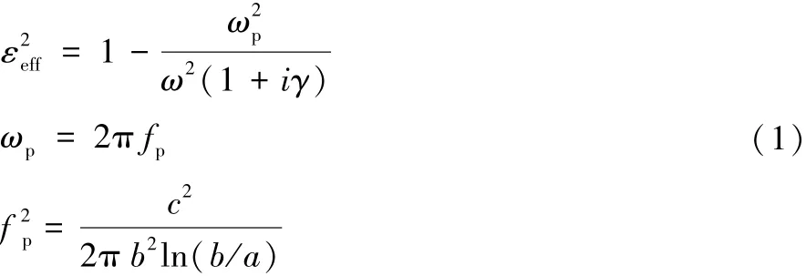
Here, γ is the relaxation parameter, c is the speed of light, a is the fiber radius and b spacing between them.
4.1.2 Fiber radius
It has been well established that,at given glass-coating thickness,the GMI effect is enhanced with increasing wire radius[38], thus, composites containing fibers with larger radius presents higher field tunability than those with smaller radius.Accordingly,the dielectric response of the composite containing wires of larger radius is stronger.This can also be understood from the perspective of skin effect:the field tunable effect tends to be smaller with stronger skin effect; therefore,the thinner wires will present weaker field effects.A very important sine qua non for realizing the metamaterial feature at microwave frequency is that the diameter of the microwire is comparable to the skin depth,as a too large diameter will cause huge reflection[39,40].Although it is still possible to penetrate into most of the inner core in the Fe-based wire or the outer shell in the Co-based wire,the submicron wires or nanowires would be preferred[26].On the other hand,reducing the wire diameter will reduce the volume fraction of wires and hence the permittivity and permeability.Panina et al.[40]revealed that the radius of the wire has a profound impact on the intensity of transmission S21but much less effect on the tunability.Qin et al.also confirmed that the wire geometry and therefore,the plasma frequency play an imperative role in influencing the patterns of scattering spectra[41].
4.1.3 Composition
A suitable composition should be identified in the early stage to ensure the final composite satisfies the conditions of operational frequency and tunability for targeted applications.Excellent soft magnetic properties which are sensitive to com-position would be preferable to realize strong field tunable effects as it has been proved that field tunable effects are positively dependent on the relaxation parameter[41].A better magnetic softness indicates a larger dynamic magnetic permeability at certain frequency range,giving rise to a larger relaxation parameter[40].Soft magnetic properties of magnetic fibers are sensitive to the composition[41]and therefore,one should try to control it during the fabrication process and tailor it further with post-fabrication treatments before the incorporation of the fibers in the composite.Generally,in terms of magnetic fiber selection,there are two categories:the Co-based and the Fe-based.Previous studies have elucidated the benefits of Cobased wires in realizing a double negative DNG feature(simultaneous negative permittivity and permeability)[42]arising from their superior GMI properties over the Fe-based counterparts and nearly zero magnetostriction constant attributed to their circumferential anisotropy.Fe-based fibers,on the other hand,have significantly different domain structure from Cobased wires arising from the positive magnetostriction,and as a consequence,its static and dynamic electromagnetic responses are also distinct from those of Co-based wires[43].Besides,the natural ferromagnetic resonance(NFMR)of Fe-based wires enables negative permeability without the aid of external fields which creates additional degrees of freedom in designing DNG metamaterial.In addition,Fe-based fibers are much cheaper compared to Co-based fibers,thereby more desirable for practical applications.
The composition of the fibers also plays a role on predicting the plasma frequency of the metacomposites.In composites containing Fe-based ferromagnetic wires arranged at a certain spacing[44],Eq.(1)fails to predict the plasma frequency fp.It is established that the dielectric response of ferromagnetic wires is controlled on the surface through modifying surface plasmons by creating circumferential magnetic field.Thus,the main dielectric response to electromagnetic waves is expected to come from the outer shell domain of wires[39].However, for Fe-based wires, the outer shell domain only occupies a rather trivial portion of the whole wire volume.From the dielectric point of view,the effective wave-matter interaction area has dramatically reduced.Luo et al.proposed the term of“effective diameter”aeffto account for the equivalent interaction area mentioned above and,fpwas modified to:

Since aeff≤a, the fpis then significantly compromised.Cobased wires possess domain structure with large volume of circular outer shell[27].Therefore, the “effective diameter” for Co-based wires would be only a touch smaller than the real wire diameter,rendering fpa bit smaller than theoretical value calculated by using the modified equation as well[44].
4.1.4 Fiber arrangement
Luo et al.[44]prepared prepreg-based metacomposites containing parallel Fe-based fiber arrays with spacing of 3,7 and 10 mm,respectively(Fig.1a)and their microwave characterization was carried in a free-space set-up in 0.9~17 GHz under a dc magnetic field up to 3 kA/m.A transmission window in S21spectra can only be obtained when the wire-wire spacing is below a spacing of 7 mm with or without magnetic field(Fig.1b).Transmission windows are a typical result of abnormal dispersion and this could be induced by either doublepositive or double-negative indices(permittivity and permeability).The observation of negative permittivity below a frequency of 16 GHz(Fig.1c), i.e.fpdenies the former situation, and thus, negative ε and negative μ are simultaneously obtained as a metacomposite feature.The negative ε is observed below the fpderived from the parallel alignment of the fibers[39],while a profile of negative μ is originated from their FMR[27].Notably,this transmission window can be excited without external magnetic fields,which is also defined as natural DNG feature and rather controlled by a critical spacing in the single Fe-based wires containing composites.This remedies the metastructure consisting of Co-based wire arrays where DNG indices can only be observed in the presence of burden magnets[42].
In addition,when the spacing is larger than 3 mm,there is a large discrepancy between the fpcalculated values with Eq.(1)and the experimental ones.Apart from the influence of compositional features as explained in Section 4.1.3,the discrepancy links to the wire-wire magnetic interaction and the modulation of fp.Decreasing the wire-wire spacing to a critical value of 3 mm, dynamic wire-wire interactions provide essential offsets to the effective diameter,hence plasma frequency considering the modification of wires"domain structure and magnetic tensor due to the long-range dipolar resonance[26,45].It should be stressed that here the interactions are referred to as the dynamic magnetic interactions resulted from the coupling with electrical component of incident waves rather than the magnetostatic coupling,since 3 mm spacing is still too wide to induce meaningful magnetoelastic energy[46].
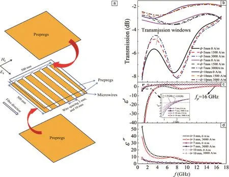
Fig.1 Schematic illustration of the process for manufacturing composites containing Fe-based microwires in parallel manner with wire spacing of b.Reprinted with the permission from[44],copyright 2013 AIP(a);Frequency dependencies of the transmission parameter S21(transmission coefficients)and b dielectric permittivity of parallel microwire composites with the presence of fields up to 3 kA/m of different wire spacing, b=3,7 and 10 mm, respectively.Reprinted with the permission from[44],copyright 2013 APL(b)
However, due to the loss generated by the wires, the transmission level is not greatly favorable in this parallel metacomposites.The root cause is the relatively high wire concentration in the case of 3 mm spacing.To overcome the drawback,the same group came up with an orthogonal array design(Fig.2a)that is capable of realizing the transmission window at much larger fiber spacing and providing a much higher transmission level[47].Transmission windows and higher transmission levels are obtained in 1~6 GHz in the metacomposite containing 10 mm-spaced orthogonal fiber array,i.e.with a much lower fiber content compared with parallel metacomposites filled with fibers of 3 mm spacing(Fig.2b).
The 90 degree wires can be regarded as an insertion of an array of discontinuous wires between neighbor continuous 0 degree wires, the “imaginary” short-cut wires enhance the wire-wire interaction via the generation of circumferential fields such that the critical spacing is reduced[47].In the orthogonal configuration, the small axial component of 90°wires along the electrical field of incident waves enhances both the dielectric permittivity and the magnetic permeability to a similar extent,which accounts for the higher transmission in the orthogonal metacomposites.
Combining different types of magnetic fibers(composition and structure)at different arrangements would also influence the patterns of scattering spectra in the metacomposites.The first idea is to incorporate Co-based fibers with Fe-based fiber arrays in the composites.Luo et al.[48]selected two combinations of Fe-based and Co-based fibers,i.e.parallel Co-based and parallel Febased wire array,and short-cut Co-based and continuous orthogonal Fe-based wire array.It was emphasized that Fe-and Cobased microwires must be embedded into separate prepregs to minimize large reflection losses caused by physical wire contacts.The Fe-and Co-based fibers in the metacomposites were arranged with 10 and 3 or 10 mm spacing,respectively.
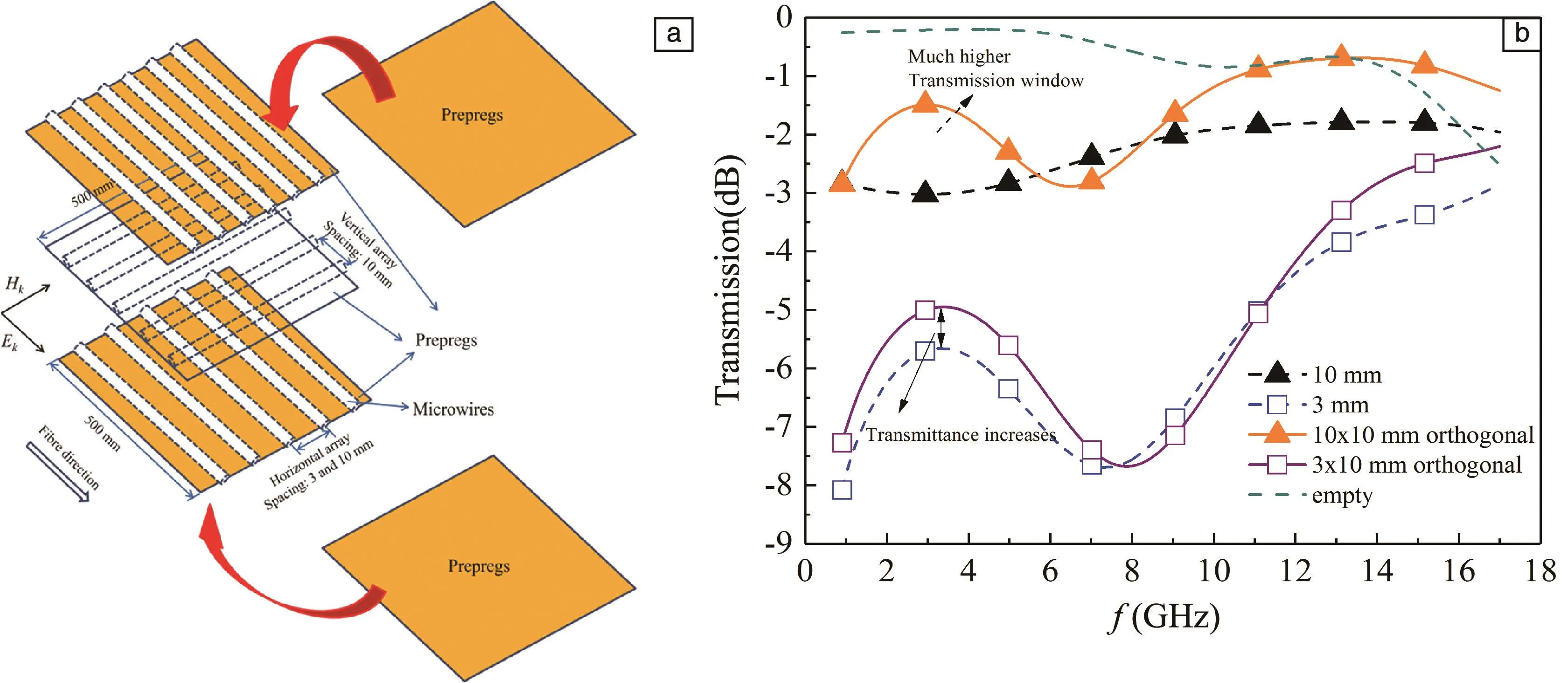
Fig.2 Schematic view of manufacturing process of orthogonal wire array metacomposite with fixed wire spacing 10 mm perpendicular to glass fibers and different horizontal wire spacing of 3 and 10 mm,respectively.Reprinted with the permission from[47],copyright 2014 AIP(a);Frequency plots of transmission spectra of polymer composites with parallel and orthogonal wire arrays and blank composite(with no wires)with electrical component along glass fibers in the absence of external fields.Reprinted with the permission from[47],copyright 2014 JAP(b)
When the Co-based fibers were arranged at 3 mm spacing,a transmission window only appeared with the presence of magnetic field and proved to be tunable with increasing magnetic field(Fig.3a),thus a magnetic bias-induced double-negative features are obtained.Further, with the external fields increasing,the transmission window peak experiences a redshift-blueshift evolution(Fig.3a)due to the dominant role of long dipolar resonance at low magnetic fields of 600 A/m induced by the interaction between wire couples[44,47], and the FMR of Fe-based wires prevailing at higher fields than 600 A/m.However,composites containing 10 mm spaced Fe-based wires are too wide to induce wire interaction reflected in no apparenttransmission window(Fig.3b)whereas single Co-based wire array suppress the DNG properties and transmission windows(Fig.3c)because of overall high reflection.Arranging the Co-based fibers at 10 mm spacing,a high-frequency transmission window was attained arising from the possible magnetic resonance between Fe-Co fiber couples.A low-frequency transmission window is revealed in the frequency band of 1.5~5.5 GHz without the presence of external fields(Fig.3d),indicating a natural DNG characteristic,which is similar to the situation above explained for the parallel metacomposites containing Fe-based fibers.Moreover,a transmission enhancement is achieved at higher frequency band of 9~17 GHz for such 10 mm-spaced thanks to the magnetic resonance between Fe-Co wire couples(Fig.3e).In conclusion,the spacing of Co-based fibers has marked effects on the metamaterial behavior of the Fe-based-Co-based composites, incorporating a more “dilute” (lessspaced fibers)Co array into the composite can broad the metamaterial operating frequency band.
Until now,we have shown a readily available fine control of metacomposite behavior via the selection of fibers with different compositions and the manipulation of their spacing and arrangement in the composite.A further approach looks at ways of incorporating fibers with different microstructure to optimize the metacomposite behavior of the composites considering that intrinsic electromagnetic properties of the microwires related to their domain structure and microstructure.Apart from doping with metallic elements such as Cu, Cr, Nb, another way to optimize the microstructure of the fibers and thus,their electromagnetic properties is by current-modulation annealing which promotes internal stress relaxation and improvement in circumferential permeability[49].Following this approach,we currentannealed Co60Fe15B15Si10magnetic fibers by using a DC current of 20, 30 and 40 mA for 10 min,to tune the transmission spectra of the composites incorporating these fibers.Further,we integrated different combinations of as-cast, labeled as A(0 mA), and annealed fibers B(30 mA)and C(40 mA)arranged on difference locations in the composite.The composites were prepared by aligning 6 fibers in a parallel manner between two facing molds with a fixed fiber spacing of 2 mm.Samples with dimensions of(22.86×10.16×2)mm3were realized after curing at 125℃for 20 min the silicone resin/curing agent mixture.
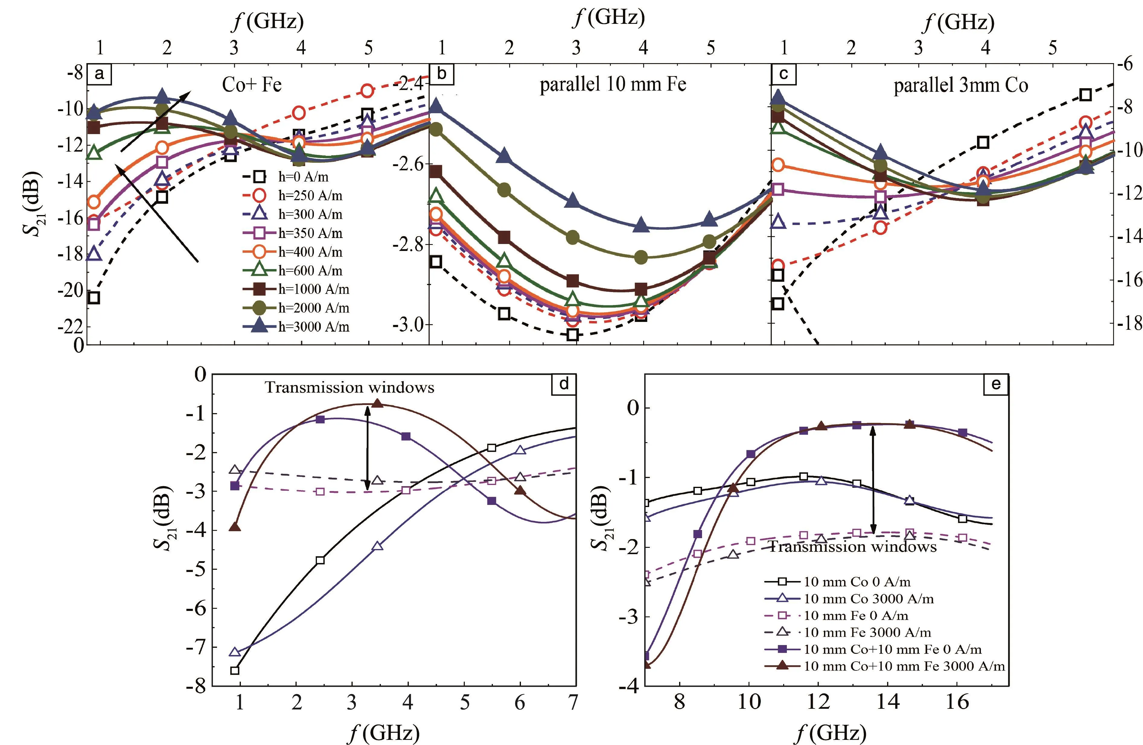
Fig.3 Frequency plots of the transmission coefficients, S21, of composite samples:(a)fiber arrays with 3 mm-spaced Co-based wires; (b)pure Fe-based wires; (c)pure Co-based wires.Transmission coefficients of composites containing 10 mm-spaced Fe-based wire array, the 10 mm-spaced Co-based wire array(d,e),and their hybridized wire arrays in the frequency band of 0.9~7 GHz(d)and 7~17 GHz(e)
Fig.4a shows the transmission spectra S21of the composites containing the individual as-cast fibers(0 mA)and annealed fibers(20,30 and 40 mA).For the as-cast sample,a transmission dip occurs at 11.96 GHz corresponding to the Lorentz-type dielectric resonance or dipolar behavior of the short wires[37].Short fiber inclusions act as dielectric dipoles when interacting with the electrical component of waves.Recalling from previous sections,the dipole resonance can betivity of the silicone matrix and fiber length,respectively.Taking εmas 2 and l as 10.16 mm into above equation, we obtain fres=10.44 GHz, which fairly coincides with the identified dip in Fig.4a.Increasing applied current on the wire shifts the transmission dip toward lower frequencies(red-shift).Initially with a small amount of DC current, i.e.below 20 mA, fresis barely affected,whereas for currents above 20 mA, the redshift is more evident.In the case of amorphous wires with a metallic core diameter in the range of 20 microns,a current of 25~50 mA corresponds to temperatures of 400~550 K which are high enough (butlower than the crystallization temperature, as evidenced in Fig.4b and Fig.4c) for structuralrelaxation and partialreliefofthe internal stresses[50].Large internal stresses give rise to a large anisotropy which is evidenced in the B-H loop of the as-cast wire(Fig.4c).While heating the fibers,induces anisotropies along local magnetizations(Fig.4c)due to short-range pair ordering and a circular magnetic field generated by the current aligns the easy anisotropy axes.Since the internal magnetoelastic anisotropy is decreased by heat treatments,the magnetic behavior is controlled by the induced uniaxial anisotropy[50].Therefore,the shift in the transmission-dip frequency may be mainly caused by the change in structural relaxation produced by current annealing.
For the composites containing combination of the as-cast and annealed fibers(Fig.4b and Fig.4c),the arrangement of the fibers has a profound impact on the transmission amplitude and transmission dip frequency of the composites.When different types of fibers are added in the same amount,i.e.AAABBB and AAACCC(Fig.4b),the transmission dip or dipolar resonance trends to lower frequency as the 30 mA-annealed fiber B is replaced by the 40 mA-annealed fiber C.This trend coincides to that of the composites containing the same type of fibers(AAAA, BBBB and CCCC),but with a most pronounced red-shift for the AAACCC sample.When the fibers are arranged in an alternate manner i.e.ABABAB and ACACAC,the transmission dip follows the same trend with frequency,i.e.red-shifting with the incorporation of 40 mA-annealed fiber C(Fig.4c).Finally,when the middle fibers in the array ABABAB and ACACAC are switched,i.e.ABBAAB and ACCAAC,the critical frequency once again shifts on the side of the 40 mA-annealed fiber C.In addition,the transmission amplitude of the composites also decreases as the fiber C is incorporated in the array(Fig.4a~Fig.4c).Therefore, we can infer a dominant influence of the annealed fibers over the as-cast fibers on dictating the electromagnetic response of the composites.

Fig.4 Transmission spectra S21for composites containing the individual as-cast and annealed fibers and the composites containing different combinations of the as-cast(a), 30 mA-(b)and 40 mA-(c)annealed fibers, respectively.Corresponds to the structural, thermal and magnetic characterization of the as-cast and annealed fibers, respectively(d~f)
The variations in transmission spectra features in the composites could be explained by the dynamic fiber-fiber interactions considering the differences in domain structure and magnetic tensors between the as-cast and annealed fibers incorporated in the array[26,47].In this case, the dynamic magnetic interactions resulted from the coupling with electrical component of incident waves rather than the magnetostatic coupling,since 2 mm spacing is still too wide to induce meaningful magnetoelastic energy[47].In the first case AAAXXX(where X corresponds to either annealed fiber),we can con-sider the largest“effective” area composed of equally structural microwires(three as-cast wires plus three-annealed wires)with different conductivity,larger for the annealed wires(Fig.5a).The same type of wires in a parallel manner constitute an increase of the total cross-sectional area S of the wires,resulting in a diminution of the effective resistivity and hence a stronger skin effect.Such “effective” area is decreased when varying the order of the wire in the arrangement,three wires of the same type are reduced to two(AXXAAX, Fig.5b)andone(AXAXAX, Fig.5c),therefore affecting the equivalent conductivity and shifting the transmission dip frequency of the composites.We then arrive to it that incorporating fibers having diverse structural features arranged in different combinations,the electromagnetic properties could be largely anticipated and programmed.Moreover,stress-relaxation and structural-change of the fibers through low-current annealing without changing the general amorphous structure and inducing severe crystallization, are only necessary to induce a significant change in the signature of the transmission spectra.

Fig.5 Interaction between the fibers with different arrangements in the composite and their corresponding “effective area”:(a)AAAXXX,(b)AXXAAX,(c)AXAXAX,where X corresponding to either 30 or 40 mA annealed fiber.Fiber-fiber interactions and couplings are stronger when the fibers are in the vicinity of their twins
4.1.5 Hybridization
Albeit metacomposite properties were obtained in the above magnetic fiber-based composites,its properties have been controlled mainly by the topological arrangement and structure of the fiber inclusions.Consequently, how to precisely control the magnitude and frequency band of negative permittivity from the material perspective as modulating the conventional composites via the fillers remains until here a major challenge.Aiming to solve this issue,we consider herein an alternative approach based on a multiscale composites idea to add another functional filler at a distinct scale to the metacomposite structure.
Besides the comprehensive performance including thermal and electrical conductivity,superb mechanical strength and excellent corrosion resistance,tunable negative permittivity parameters have also been achieved in polymer composites by incorporating different carbon structures like graphene,carbon nanofibers, carbon membranes and carbon nanotubes(CNTs)[51-53].The distinctive effective dielectric response of composites including carbon structures has recently led to the development of high-performance metamaterials[22-26].The experimental results indicate that the electromagnetic properties in these composites can be tailored by controlling the size of the conductive carbon network.In this context,due to the diverse array of their properties,we may infer that a combination of amorphous wires with nano-carbons could be a feasible filler to constitute a novelmetacomposite towards tailorable dielectric properties[54].In a previous work,we have already demonstrated the validity and flexibility of this“complementary hybrid”approach to addressing the rational design of microwave absorption features[55].
Our approach consisted of integrating the CNTs or graphene oxide(GO)with the Co68.15Fe4.35Si12.25B15.25amorphous wire(AW)with a diameter of 70 μm by directly coating them onto its surface via an electrophoretic deposition process(EPD).By increasing the CNT content through variations in coating thickness,we could control the size of the conductive CNT network formed and therefore the conductivity mechanism which will be reflected in the negative permittivity response.Similarly,regulating the number of oxygen-functional groups in GO through thermal annealing would lead to distinctive carbon configurations and hence unique signature in response to the electromagnetic wave.For the EPD process,the applied electric field and deposition time were the crucial parameters to control the deposition yield and thickness.For CNT,the process was carried out at 10 V(or electric field of 5 V/cm)for 60 and 120 s and at 20 V(or electric field of 10 V/cm)for 60 s.Thus,different coating thicknesses were obtained((1.73±0.30)and(2.81±0.11) μm for 10 V series and(3.11±0.26) μm for 20 V series).These samples were labelled, respectively, CNT/AW-1.73 μm, CNT/AW-2.81 μm and CNT/AW-3.11 μm.The deposition of GO on the wire surface was accomplished at 20 V for 90 s,and a coating thickness of(2.35±0.36) μm was obtained.The wires coated with GO were then annealed at 300 and 500℃for 1 h(referred to as rGO/AW-300℃and rGO/AW-500℃)and finally at 900℃for 0.5 h(as rGO/AW-900℃)to sequentially remove oxygen-containing functional groups from the GO coating and obtain rGO/AW hybrid fibers.
Prior to their deposition,the CNT were chemically oxidized to remove metallic catalysts and introduce carboxyl acid groups on the CNT surface.The presence of the carboxylic groups on the surface of oxidized CNTs provided a negative surface charge, and as a result, the CNTs deposited electrophoretically on the amorphous wire acting as an anode.On the other hand,graphene oxide(GO)was prepared by a modified Hummers"method[56,57].Briefly, graphite powder(2 g)and NaNO3(1 g)were added into concentrated H2SO4(46 mL,98%),the mixture was kept in ice bath(0℃)for 0.5 h.After that,KMnO4powder(6 g)was added to the mixture slowly and stirred continuously for another 3 h.Afterwards,the mixture was heated to 35℃ for 0.5 h,and then deionized water(46 mL)was gradually added to the above mixture.The temperature of the mixture was increased to 98℃and kept for 0.5 h,36 mL H2O2and 200 mL H2O were subsequently introduced.When the whole reaction was completed,the final solution was washed with HCl(5wt%)and deionized water until the pH was~7 to finally obtain the GO aqueous solution for the EPD process.The GO solution was negatively charged due to the abundant electro-negative oxygen species(epoxy,carboxyl,carbonyl and hydroxyl)and hence could be electrophoretically drawn to the amorphous wire.After preparing the nanocarbon/amorphous wire hybrid fibers,two types of composite samples were prepared containing the CNT/amorphous wire and rGO/amorphous wire hybrid fibers into silicone resin/curing agent mixture,respectively.The composites were prepared by aligning three hybrid fibers in a parallel manner between two facing molds with a fixed fiber spacing of 3 mm.Electromagnetic parametersweremeasured in aWR-90 waveguide in TE10dominant mode from 8.2 to 12.4 GHz.
SEM images and elemental mapping showed that the nano-carbon coatings were successfully deposited on the amorphous wire(Fig.6).Initially,the nanotubes forests are isolated in islands of various sizes supported by the underlying amorphous wire.Increasing the deposition voltage gives a more uniform CNT layer; as the CNT content increases, the nanotubes gradually connect with each other and nanotube networks can be easily formed.These differences are crucial in determining the negative permittivity behavior in composites containing the CNT/AW hybrid fibers,as will be elucidated later.For the rGO/AW fibers,the rGO coatings treated at different annealing temperatures have the same basic morphology showing distinctive graphene flakes dispersed on the surface of the wire.However, with increasing annealing temperature, the flakes appearthicker, which can be attributed to the restacking issue and the likely thermally induced aggregation.
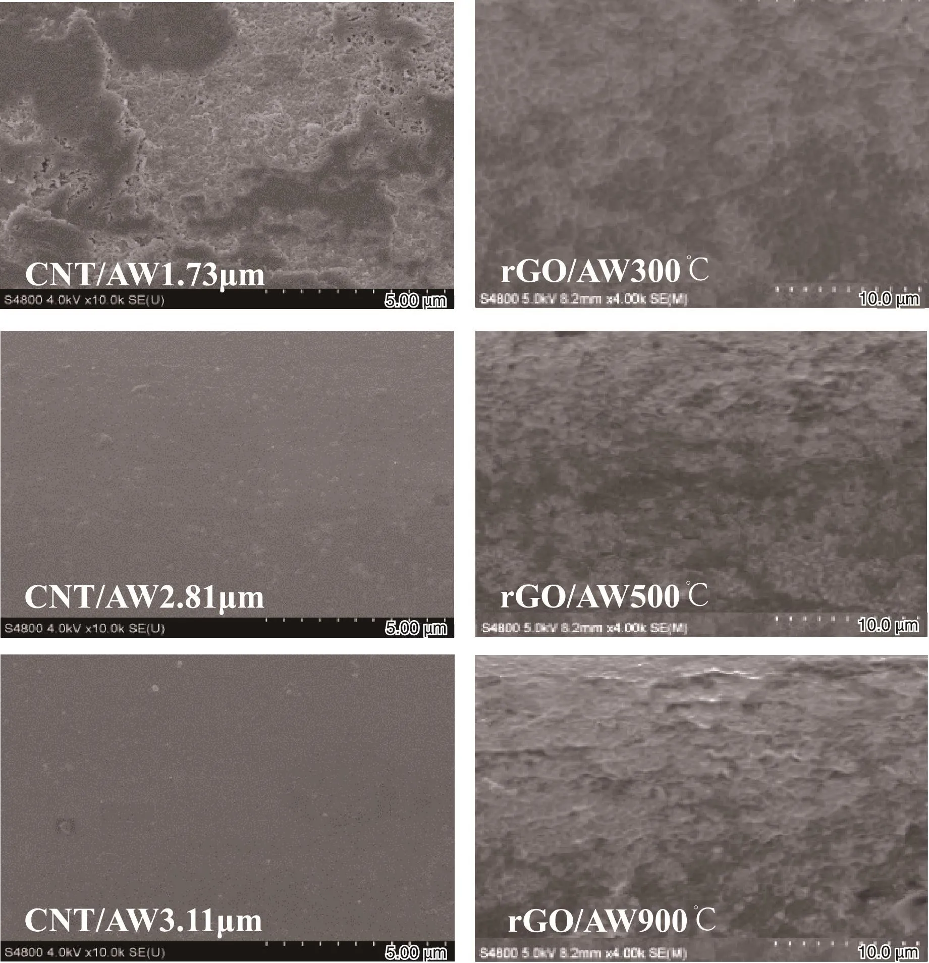
Fig.6 SEM images of CNT/AW hybrid fibers at different coating thickness(left panel)and rGO/AW hybrid fibers at different annealing temperature(right panel).Reprinted with the permission from[54],copyright 2019 Elsevier
Fig.7a shows the effect of CNT coating thickness on the permittivity spectra.As the CNT coating thickness is increased,a conversion of dielectric dispersion from Lorentz resonance to Drude plasma oscillation occurs, which is ascribed to the degree of inter-connection between the CNT networks in the coating.For the wire coated with 1.73 μm CNTs,owing to the non-uniformity of the CNT coating(Fig.7b),the Lorentz type dielectric resonance should result from the induced electric dipole in isolated CNTs[58].Here,the electrons implement the macroscopic conductivity via hopping between adjacent CNTs under the effect of high-frequency electric field(Fig.7b)since the majority of electrons are localized[58].Because of the high aspect ratio of the CNTs,a further increase in CNT content leads to the inter-connection of nanotubes helped by the circular-shape conductive substrate(amorphous wire)which reduces the energy barrier between CNTs.Such interconnection forms the current loops which make the electrons delocalized(Fig.7b).Hence,we observe a Drude plasma-like negative permittivity behavior caused by the low-frequency plasmon of free electrons in CNT networks.
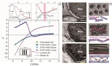
Fig.7 Frequency dependence of permittivity of composites containing the CNT/AW hybrid fibers with different CNT coating thickness.The insets show the Lorentz and Drude parameters extracted from the permittivity spectra of CNT/AW-1.73 μm and CNT/AW-2.81 μm representative samples(a);Structural evolution of CNT coating and illustration of the associated conduction mechanism(b).Reprinted with the permission from[54],copyright 2019 Elsevier
Fig.8a shows the real permittivity spectra for the rGO/AW hybrid fibers treated at different annealing temperature.For GO/amorphous wire sample,the permittivity is positive and almost independent of frequency.Thus,the amorphous wire seems to have a limited contribution to the effective permittivity of the whole composite,and its response should be strongly influenced by the GO/rGO coating.When the hybrid fiber is annealed at 300℃,the permittivity curve changes abruptly and resembles that of the CNT-1.73 μm coated amorphous wire,and the Lorentz model is applicable.Further thermal reduction of GO/AW fibers transforms the permittivity frequency dispersion from resonance-induced to plasma-like behavior and the permittivity curves for rGO/AW-500℃,and rGO/AW-900℃samples follow closely the metal-like negative permittivity according to the Drude model.The gradual restoration of sp2domains and thus expansion of the delocalized π-electron network upon GO thermal reduction are responsible for such conversion in the GO-coated wires.The carrier transport properties in rGO/AW-300℃hybrid fiber composites can be depicted by a hopping model via the localized states in the large energy gap(Fig.8b), therefore, leading to a Lorentz-type dielectric resonance.Further thermal reduction of the hybrid fibers creates new and large sp2clusters caused by the gradual restoration of the graphitic structure through the removal of oxygen,which provide pathways between sp2domains already presentand mediate their transport[59,60]. The expansion of the delocalized π-electron leads to a decreased potential barrier among domains and continuous conduction with small energy gap becomes possible.
In addition,the dielectric parameters such as negative permittivity magnitude, plasma frequency, Lorentz and Drude damping are determined by interfacial conditions,defects and surface roughness of nano-carbon/AW hybrid fibers.The results obtained confirm an effective strategy to realize tunable metacompositesbased on magnetic nano-carbon basedmaterials and offer an alternative to integrate the design philosophy of multiscale composites and hybridization to that of metacomposites.
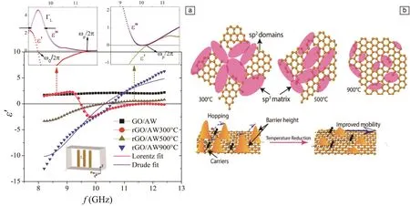
Fig.8 Frequency dependence of permittivity of composites containing the rGO/AW hybrid fibers at different annealing temperature.The insets show the Lorentz and Drude parameters extracted from the permittivity spectra of rGO/AW-300℃and rGO/AW-500℃representative samples(a);Schematic representation of the structure evolution of the sp2/sp3domains with reduction temperature and associated carrier transport mechanism(b).Reprinted with the permission from[54],copyright 2019 Elsevier.
In Section 4.1.4,we concluded that a periodical array of Fe-based ferromagnetic microwires is proper building block in metacomposites due to their tunable ferromagnetic resonance and tailorable geometrical characteristics.Hybridizing such microwire building blocks with another functional fiber-reinforced polymer composite could further broad their electromagnetic capabilities.Carbon fiber reinforced polymer(CFRP)composites are widely used in aerospace and automobile industries as load-bearing components due to their light weight,high structural strength and excellent anti-corrosion abilities[61,62].Embedding microwire building blocks into CFRP composites to develop single negative(SNG)or DNG properties is of enormous practical importance in the integration of,e.g., zero-loss structural health monitoring, microwave cloaking and perfect absorbing techniques into existing CFRP components.The outstanding mechanical performance of the microwires can guarantee that the overall structural properties of the metacomposites can still meet the engineering criteria.However, to effectively design such metacomposites, the concentration of carbon fibers should be carefully designed due to their electrically reflective nature and thus the difficulty to extract useful electromagnetic parameters from the composites.Additionally,the orientation of carbon fibers needs to be considered which causes the metamaterial features highly anisotropic to external excitation directions.To overcome such issues,we designed and manufactured CFRP metacomposites containing continuous and short-cut Fe-based microwires.
Amorphous glass-coated Fe77Si10B10C3microwires with the total diameter of 20 μm and a Pyrex glass coating of 1.7 μm were fabricated by a modified Taylor technique.Processing parameters such as wheel rotating speed,cooling water distance were carefully selected to promise a near-perfect cylinder geometry with decent roundness and surface.Subsequently microwires were embedded into aerospace-graded carbon fiber reinforced prepregs(IM8557,Hexcel)in a parallel manner with the spacing of 3 mm.The geometry of the containing carbon fiber prepregs was arranged as prepreg patches((80×10)mm2)and continuous prepregs((500×500)mm2),respectively(Fig.9).Note that microwires should be perpendicular to the direction of carbon fibers to minimize reflection loss[26].Two additional GFRP prepregs((500×500)mm2)were used to host microwire-GFRP layer by a hand layup followed by a standard autoclave curing(details on the manufacturing of metacomposites will be given in next sections).Apparently,simply spreading carbon fibers on the surface of wire-composites is not correct since microwave signals will be fully blocked and prevented from further interacting with microwires within the composites.Instead,carbon fibers and microwires should be included in the middle prepreg layer covered by additional glass-fiber prepreg panels during the laying-up process.Microwave measurement was carried out by the free-space technique in the 0.9~17 GHz with an external dc magnetic bias swept between 0 and 3000 A/m.S-parameters were extracted during the measurement and then calculated into permittivity and permeability using Nicolson-Ross-Weir method via a modified built-in computing programme.

Fig.9 Schematic illustration of metacomposites containing 3 mm spaced parallel Fe-based microwires and continuous(a)and short-cut(b)carbon fibers
To overcome the lack of tunability of microwave properties with magnetic field of short-cut CFRP metacomposite,continuous carbon fibers are introduced to ameliorate the impedance match of wire-composites.Fig.10 describes the transmission and its phase of the continuous CFRP metacomposite in the 0.7~17 GHz with magnetic fields up to 3000 A/m.When the electricalcomponentofmicrowavesisplaced along the microwires,a series of transmission windows are obtained under different magnetic fields(Fig.10a).A reverse in phase velocity,i.e.from negative to positive values and negative permittivity values(inset of Fig.10a and Fig.10b suggest that the DNG property of such microwire-composite still persists).The reasons are two-fold.First of all,the dielectric epoxy in the prepregs prevents free charge movement among carbon fibers.The parallel microwire array can still be regarded as plasma if E is along wires,therefore conspiring to the negative permittivity values[63].Secondly,insulating glass-layer on the wires can avoid hopping or free charge movement from microwires to the conductive polymer matrix.Thus, the electrons are “trapped”within the metallic cores,rendering wires as perfect electric conductors(PECs).On the other hand, however, the transmittance level,is decreased compared with the 3 mm Fe-based parallel GFRP metacomposite, e.g., from-5.6(52.5%)to-7.8(40.7%)dB at zero field[44]due to the increase of overall conductivity of composites arisen from integration of a greater amount of conductive carbon fibers therein.Notably,with the increase in external fields,the observed windows are tunable with linearly enhanced amplitudes, i.e., the waves can be quantitatively controlled to pass the microwire metacomposite by an application of magnetic bias(Fig.10a).The maximum amplitude variation under different fields reaches 2.4 dB at 3.5 GHz which equals to 78.5%of the total incident microwave signals.Interestingly,embedding microwires into the carbon fiber reinforced composites still preserves the DNG properties,providing microwires are overlapped with carbon fibers in an orthogonal manner.
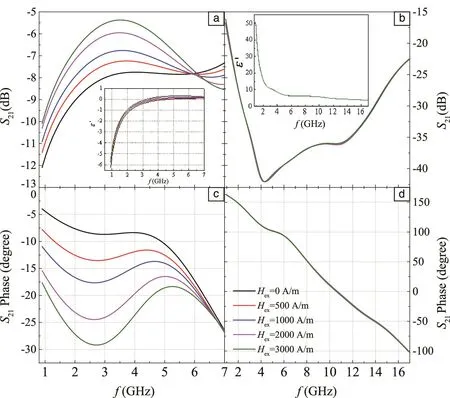
Fig.10 Frequency plots of transmission spectra of continuous carbon fibers contained hybrid metacomposites with E placed along(a)and perpendicularly(b)to microwires.Frequency plots of transmission phase of the same composite in(a)/(b)with E along(c)and perpendicular(d)to microwires.The insets in(a)and(b)are the frequency dependences of their e′when E is along and perpendicular to microwires,respectively
Hybridization, therefore, offers more perspective applications thanks to the involvement of other type of fillers chemically or physically mixed with the wires in the polymer,enriching the content of the“multifunctionalities” derived from the microwires and consequently opening up new arena of research subjects and innovative technologies such as the application of smart composite materials in aeronautical electronics.
4.2 Tunability achieved by external stimuli
4.2.1 Magnetic field
In former sections we already had a glance at the effect of magnetic field on tuning the double negative properties of the composites.The negative permeability could be adjusted by taking into account the ferromagnetic resonance(FMR)frequency and ferromagnetic anti-resonance(FMAR)of the wires.The permeability parameteris ratherinsensitive to moderate magnetic fields since at such frequencies the condition of the ferromagnetic resonance requires a much stronger magnetic field.Meanwhile, for the wire radius in micron scale, and wire spacing in mm scale,the plasma frequency which determines the frequency dispersion is in the GHz range.In this frequency band,the permittivity dispersion may be used to engineer a specific tuneable electric response by changing the losses in the system with an external magnetic field which produces a change in the wire magnetic configuration[40].The underlying physical mechanism involves a large magnetoimpedance(MI)effect.The extent of the field tuning depends not only on MI but also on the geometrical parameters of the wires and their spacing,which was confirmed in the results previously shown[44,47,48].Thus,it is viable to modulate or optimize the microwave dielectric properties and transmission/reflection patterns of the composites through tuning these wire parameters,which can also be utilized to extend the limitation of the effective operation frequency range.When it comes to the design and manufacture of such kind of microwire composite for field tunable functionality,careful choice of wires proves to be critical to the ultimate performance of the resultant composites.
4.2.2 Stress
Due to the stress effect on the impedance of amorphous wires,the stress will have a significant impact on the propagation of microwaves when they pass through the microwire in the composite.This is characterized by the variation of electromagnetic parameters(reflection, transmission, permittivity and permeability)with stress.For stress-sensitive composite materials,it is important to have a substantial deviation of the anisotropy from the circumferential direction in the ideal case axial anisotropy would be preferred[64].As we explained before,for composites containing ferromagnetic wires exhibiting a giant magnetoimpedance effectatmicrowave frequencies, the effective permittivity may depend on a dc magnetic field via the corresponding dependence of the surface impedance.On the other hand,the surface impedance can also be changed by applying a stress which modifies the magnetic anisotropy and domain structure in the wires,therefore modifying the effective permittivity.It follows that the stress-impedance(SI)property of microwires is critical to the susceptibility of the whole composite to the stress which depends on the magnetoelastic characteristics of the microwire conditioned once again by composition, domain structure, geometry, etc.This accounts for the variable sensitivity of the microwire composites in terms of their permittivity to the external stress when different wires are incorporated in the composites[41].For example,in the case of Cobased microwires with a negative magnetostriction,when a stress is applied along the axis of the wire,a magnetoelastic field is induced in the circumferential direction and this drives the spins rotating towards that direction.As a result,the circumferential magnetic permeability is decreased, and hence,the surface impedance is also reduced.Itis expected,therefore,that the application of a longitudinal stress will compensate the effect of the magnetic field.Afterwards,with increasing stress,the well-defined circumferential anisotropy may remain unchanged and hence the surface impedance shows very little variation to the incremental stress,with a minimum of tunability.Larger stresses may depreciate the circumferential anisotropy and increase the surface magnetoimpedance,which recover the tunability with stress.
Apart from the optimization of composition and magnetic structure ofthe fillers, anotherway to improve stress sensitivity is by increasing the amount of microwires in the composites.However,it does not necessarily mean that the more the better.In Co-based amorphous wires,increasing the number of wires in the composite from 6 to 17,the sensitivity of permittivity to stress showed little change.This observation suggests an independence of the stress sensitivity in wire composites to the conductivity and magnetic permeability of the wires for a sufficiently high concentration of wires,although the reason for this result remains to be explored[41].
4.2.3 Current
Here,we will demonstrate the in-situ current-modified electromagnetic behavior of microwire arrays.To this end,we chose a single wire of Co68.7Fe4Si11B13Ni1Mo2.3(total diameter of 24 μm, metallic core diameter of 22 μm)and Fe74.87Si11.99-B9.06C4.08(total diameter of 21 μm, metallic core diameter of 19 μm)and compared their microwave response to the electrical stimuli.The wire was placed on a special designed paper frame in which a rectangular window was cut(22.86 mm×10.16 mm)at its center,matching the size of the waveguide frame,a vertical grid were also drawn to ensure the wire were properly located(Fig.11).The microwave measurements were performed in the WR90 waveguide in 8.2~12.4 GHz in TE10dominant mode(electric field Erfparallel to the axis of the wire and the magnetic field Hrforiented perpendicular to the wire).The DC currents of 20 and 40 mA were applied along to the wire by the current source during 40 s.In addition,we also studied the effect of static magnetic field H0,by placing the waveguide in a Helmholtz coil.The whole setup was connected to a vector network analyzer(VNA)to measure the S-parameters of the array(Fig.11).Under this setup the instantaneous electromagnetic response of the wires can be explored.
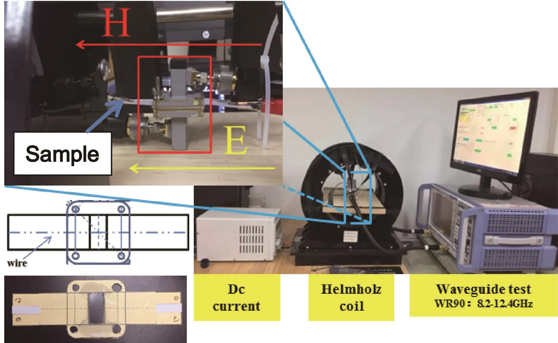
Fig.11 Complete setup for the evaluation of microwave properties of Co-based and Fe-based single wire under electrical and magnetic stimuli
In the absence of external magnetic bias(H0=0),the Fe-based and Co-based single wire behave as a partially transmission and two transmission structure(high and low frequency), respectively, that is more and more transparent with increasing frequency(Fig.12).With increasing the current,the transmission curves of Fe-based wire shift upwards,while the transmission amplitude of the Co-based does not show a significant change.Thus,it seems that the application of DC current has an important effect on the conductivity of the Fe-based microwire.In addition, for both type of wires, no blue-shift or red-shift is induced,mainly because the circumferential magnetic field induced by the DC current is insufficient to alter the internal magnetic domain structure.

Fig.12 (a)Scattering parameter S21(transmission coefficient)as a function of frequency for Co-based and Fe-based single wire under electric stimuli(b)and(c)Transmission spectra for the single wire(b)when a DC current is applied along the wire without the presence of magnetic field and when the DC current is applied simultaneously with the static magnetic field for Co-based wire and Fe-based,respectively
When an external magnetic field is applied along the wires,the transmission response for both kind of wires decreases.A small magnetic field of 637 A/m is only required to blue-shift the transmission spectra of all the curves.Moreover,increasing applied current shifts the transmission toward lower frequencies(red-shift).Therefore,the S21parameter of the Co-based amorphous wire is very sensitive to a DC current applied simultaneously with the static magnetic field.In comparison,even with a much larger external magnetic field stimuli up to 7.96 kA/m only an upward shift of the transmission can be accomplished in the Fe-based microwire.The better tunability of the Co-based amorphous wire is due to the excellent soft magnetic properties and giant magnetoimpedance(GMI)effect which has been proved to confer field and stress tunable properties to these microwires[27].
The above results confirm the tuning of transmission characteristics of ferromagnetic microwires through electrical and magnetic field stimuli.The tuning features of the studied structures are of great relevance in the metamaterial context,owing to the possibility of extending the operational bandwidths.
5 Manufacturing and application prospects of metacomposite materials
The manufacture of metacomposite materials is primarily reduced to solve the automation of the prepreg machining and the fiber/prepreg placement and combination before the preform procedures and final curing can even begin.The first step for composite fabrication is to cut the prepregs,based on the structural design.Today,with the increase in composites production facilities,more industrial parts being produced and tighter part tolerances and specifications,manual cutting is no longer viable.Fully automated prepreg cutting machines are now used to cut prepregs.Automated cutting equipment can speed up production times and reduce labour costs.The key features of the machine are optimal material usage by using nesting software, and differentshapes/profiles of prepregs can be cut with required orientations.Fig.13 shows an example of an automated cutting machine.With such machine we are able to cut prepregs with great accuracy and edge quality,without sacrificing speed.The laser pointer allow us precision pointing less than 0.76 mm at the vibration frequency of 200 Hz.
The next step in the pre-mold process is the layup of the prepregs and fibers.While manual layup can allow for a high degree ofdetails in preform manufacturing, automatic processes have proven to be more economic and less prone to human error during the critical pre-mold steps.To charge the prepreg machine with the reinforcement microwires we employ a unique winding system that pulls the prepreg around a series of evenly space pins at each end of the machine(Fig.13).While the madrel rotates at a pre-programmed rate of speed,the winding head pulls the impregnated wire back and forth around the pins in true 0°orientation, until a pipe shape is formed thathasbeen builtfrom all-longitudinalwires.Succesive layers are added at the same or different winding angles until finished thickness is reached.Using this setup we are able to control winding angles and the placement of the reinforcement(Fig.13)
The last stage in the manufacture of fiber-incorporated composites involves the autoclave curing.For this purpose,we use an aerospace-grade ASC autoclave(Fig.14)equipped with a curing chamber of(1.6×2)m2, maximum working pressure of 0.7 MPa and maximum working temperature of 250℃.Our autoclave comes with controls, part thermocouples, part vacuum lines, and the ability to apply cooling to the part, thus increasing production time and allowing for the safe handling of the parts post cure.Using this autoclave,we are able to produce parts with finer detail, tighter tolerance, lighter weight,increased strength and lower porosity.
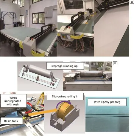
Fig.13 Gerber digital DCS 2600 prepreg cutting machine(a);Prepregs and fiber winding machine for the preparation of microwire-epoxy prepregs(b)

Fig.14 Aerospace-grade ASC autoclave for the curing of the fiber-incorporated composites(a);Microwire-glass fiber composites(b)
Upon understanding the influence of composite architecture such as material parameters of fibers,fiber periodicity and composite manufacturing,we are ready to move on to describe perspective application.The above results demonstrate strong possibilities of wire metacomposites in developing cloaking devices due to the specifically enhanced transmission spectra.The wire metacomposites could be also used in radiofrequency identification(RFID),a contactless data capturing technique to automatically identify an object using radio-frequency waves.The object to be sensed is coded with a tag that can reflect a unique pattern in terms of electromagnetic parameters.Applications of RFID for include inventory control in warehouses, supermarkets, hospitals and military thanks to its low-cost and long range sensor design platform.However,some issues such as intricate shapes and parasitic coupling with the electromagnetic waves rather complicate the signal interpretation.Composites containing microwire arrays offer a versatile solution and a simple structure that could be incorporated into the objects to be detected with each object having a unique ID coded in these composites.
The use of microwire metacomposites could enhance the radiated power of an antenna.Negative permittivity and permeability of these engineered structures can be utilized for making electrically small,highly directive and reconfigurable antennas.These,metacomposite based antennas will demonstrate improved efficiency and bandwidth performance.Metacomposites are promising candidates as antenna substrates for miniaturization, sensing, bandwidth enhancement and for controlling the direction of radiation.They could be also suitably designed to use as radome.Radome is a covering to protect an antenna from rain, wind perturbations, aerodynamic drag and other disturbances.For example,by embedding wire arrays structures inside a host dielectric medium, the desired material parameters of the composite material can be adjusted to desired values of interest.
Aircraft components and the composites they"re built from need to be as light as possible(while still able to carry out their role).These components often carry high loads,and their lightweight nature means that even small flaws can lead to failure.Testing for flaws is essential,but needs to be carried out in a non-destructive way.In general,failures occur when a component or structure is no longer able to withstand the stresses imposed on it during operation.Non-contact methods such as ultrasonic and acoustic testing, for example, allow us to detect existing defects only.They provide no indication of internal stresses in a material or stress distribution throughout a structure.Traditional methods for stress monitoring are contact-based,requiring physical tag attachment to a material.Ferromagnetic microwires embedded in polymer composites can be used to form a system that will be sensitive to applied stress.The tensile stresses in the composite material surrounding the microwires affect the way the wire material reacts to an external magnetic field.This means stress level can be measured without direct contact.It requires no physical contact because it could be embedded in the material at the required depth during manufacturing.This structural health monitoring technology requires a single sensor,unlike other popular testing methods that require placing sensors on both sided of a part to be monitored.Therefore,it makes the process of stress monitoring of composite materials much easier,faster and more efficient, allowing it to not only detect, but also to some extent predict the emergence of defects without direct contact.
6 Summary and Outlook
Our review delivered the essence of metacomposites design,mainly focused on magnetic fiber-reinforced resin matrix composites as a real composite material following the structure property relationship.Ferromagnetic microfilaments offer a solution to realize isotropic double negative medium ε<0, μ<0)with relatively simple structure consisting of only wire arrays,as opposed to the conventional complex structure constituted by the conducting wires and magnetic materials or SRRs.Their metacomposite properties are readily tunable through tailoring inner factors in the composite, such as spacing, filler properties,geometry or filler hybridization and external factors such as magnetic field,current and stress application.It is viable to modulate or optimize the microwave dielectric properties and transmission patterns of such composites through tuning those parameters which can also be exploited to extend the limitation of the effective operation frequency range.The automation of prepreg layup and autoclave curing processes have also proved efficiency and cost effectiveness for the composite manufacturing oriented towards aerospace and automobile industries while restraining modest defects.
Since fpis dramatically increased with the decrease of spacing b(Eq.(1)),to anticipate higher operating frequencies,a higher loading of fillers is therefore necessary to decrease the spacing among fillers.Therefore filler dispersion strategies such as surface functionalization are required to improve the filler distribution and hence the electromagnetic response of the metacomposites.Here,interfacial properties of the fibers and the matrix require more detailed study.In practical applications,the microwire is supposed to be embedded in matrix,introducing its functional capacity without dwarfing the mechanical property of the composites dramatically.The interfacial surface becomes crucial,deciding the adhesion quality between microwires and the matrix as well as the effectiveness of stress transfer.
The metacomposites shown in our review focused were mainly thin-ply metacomposites containing one or two layers of fiber arrays.In such structures the through-thickness electromagnetic response is neglected assuming weak coupling of microwires between different prepreg layers.A multilayer structure provides the opportunity to study the electromagnetic field propagation through the metacomposite thickness.It is predicted that with increasing wire containing prepregs,through-thickness response will be gradually enhanced and likely to interact with in-plane metamaterial performances.However,the internal structural complexity would be increased,rendering the prepreg layup rather time-consuming.Alternatively,one can develop a 3D structure comprised of printed wires followed by impregnation into a polymer matrix.The multilayer structure could not be only composed by microwires but it could also incorporate other functional fillers alternately stacked such as graphene.Electromagnetic parameters could also be manipulated by adjusting the structuralfeatures ofthe hybrid fibers incorporated in the metacomposite.Introducing a hollow or porous nanocarbon coating for example would provide a tunable degree of inter-connection between the nanocarbon networks and therefore a tunable dielectric dispersion in the composites.Further,morphing composite structures present multi-stable states achieving a wide range of performance goals, such as increasing aircrafts’ cruise flight efficiency.A combination of continuous carbon fiber reinforced polymer metacomposites and morphing structures would introduce a transmission window that can be turned on/off and even precisely regulated by managing and controlling internal stresses within the structures.For this end,advanced manufacture techniques such as 3D/4D printing should be adopted;it is therefore reasonable to be anticipated that more intricate metacomposite structure with unexpected properties will be developed in the near future.
