Effect of edge transport barrier on required toroidal field for ignition of elongated tokamak∗
2019-04-13CuiKunYang杨翠坤MingShengChu朱名盛andWenFengGuo郭文峰
Cui-Kun Yang(杨翠坤),Ming-Sheng Chu(朱名盛),and Wen-Feng Guo(郭文峰)
1Institute of Plasma Physics,Chinese Academy of Sciences,Hefei 230031,China
2University of Science and Technology of China,Hefei 230031,China
1.Introduction
Ohmic heating is the easiest and the most effective method of heating the plasma.[1]Therefore using Ohmic heating to achieve plasma ignition is the most desirable ignition path.To realize this goal,we are faced with two challenging technical issues.First,Ohmic heating loses its effectiveness when the plasma temperature gets too high.Therefore,we have to employ large current to reach ignition temperature before Ohmic heating loses its effectiveness.Second,consequently,a strong toroidal field is needed to maintain the plasma equilibrium and stability and also the plasma transport must be reduced to assure that the ignition condition is achievable.Ohmic ignition of the tokamak has been proposed by many authors.[2–6]The critical issue is that the marginal toroidal field(BT)for a plasma with elongation κ∼1 is required to be as high as about 20 T.[3]This is at or beyond the limit of the existing technologies.It was proposed in Ref.[4]that the marginal BTcan be reduced by elongating the tokamak.It was shown that with elongation∼5,the marginal BTcan be reduced to∼6 T.Then it is well within the limit of existing technology.
The zero-dimensional(0D)system models,when properly bench-marked against full transport codes,have been found to be extremely useful in design studies.If we generate 0D models based on the calibrated one-dimensional(1D)profile models,we can obtain some extra information regarding the effects of profile on the 0D models.Especially,if the profiles are modified from the profile used in the bench mark,then we can use this to obtain perturbative information regarding the effect of these modified profiles.We apply this method to the study of Ohmic ignition of an elongated tokamak.In previous study,a 0D ignition model was generated by using a set of 1D profiles(This set of profiles is defined as ‘I’model hereafter.)The ignition phenomenon is analyzed by using the 0D model.Particular cases were then bench-marked against transport code runs,establishing its validity.However,the study was made relatively early,before the identification of the possibility of an edge transport barrier.[7,8]It is natural to inquire whether the presence of the edge barrier can help us reduce the required marginal BTfor ignition.This is the main purpose of the present paper.
In the present paper,we study this question by generalizing the 1D profiles(‘I’model)that were used in Ref.[4]to include an edge transport barrier.Most of the analyses made in Ref.[4]can be readily repeated because the structure of the problem is not changed.A seemingly counter intuitive conclusion is reached:the effect of an edge transport barrier would increase the marginal BTfor ignition.Of course,in existing experiments,the achieved edge transport barrier is relatively small.The resulting small increase can be absorbed into the design margins.But more extreme profile modifications have been proposed.Also,we try to understand the physics reason underlying the result of this new discovery.
To obtain our conclusion regarding the effect of edge barrier,we implement two possible edge barrier models.The first edge barrier model is that the edge barrier effect on the pro-file is assumed to be mainly limited to the edge;it does not penetrate all the way into the center.This is close to the case where the extreme edge is cleaned by using a lithium wall.We call this profile model the ‘DC’profile model.The second edge barrier model is the model that is induced by the H-mode.In this type of edge transport barrier,the whole profile can be considered to be lifted up by an amount that is equal to the amount caused by the edge barrier.This is called the‘H’profile model.Both types of profile modifications imply‘improved edge confinement’.Although the profile modifications improve the edge confinement to different extents,they lead to similar results of‘higher’marginal BTrequired for ignition.One hypothesis is that the edge transport barrier actually results in broadening the profiles of the various physical quantities such as density,temperature,and current.Although broadness and peakedness are intuitively clear concepts,to be more precise,we define the broadness br of a profile ξ (ρ)as

The peakedness is pk=1−br.(It is quite clear that br=1and pk=0 for a flat profile with ξ =ξ(0).For a profile that is peaked at the center ξ= ξ (0)δ(0),with δ(0)being the Kroneker delta function,then br=0,pk=1).We note that the broadness defined here is closely related to the average of the profile across the plasma cross-section,and for a large aspect ratio torus it is also the same as the average of the profile across the plasma volume.It is specifically defined here to make our discussion more precise.
To further strengthen our hypothesis,we go on testing more general profiles and we obtain the following conclusion:a broader profiles will lead to a higher required marginal BT,whereas a more peaked profile can bring about a lower required marginal BT.This conclusion is further confirmed by using a set of profiles that are more general than those used in Ref.[4].Therefore,introducing an edge transport barrier is just a means in broadening the plasma profile.This phenomenon is due to the concentration of the fusion energy production needed for ignitionin near the center of the plasma.Broadening the profiles actually moves the fusion energy input away from the center,which is required for ignition.A fictitious model in which the energy input profile could be modified is examined.It is found that the trend of the required margin BTinfluenced by the transport barrier can be substantially modified.Application of this result can lead to the benefits expected from the transport barrier.
The rest of this paper is organized as follows.In Section 2,we briefly review the model and method of analysis of Ref.[4].In Section 3,we analyze the effect of profile variation on ignition.First we introduce two different models to study the effect of incorporating the edge transport barriers.In Subsection 3.1 we study ‘DC’type of profiles,in which the effect of the edge barrier does not propagate to the plasma center.In Subsection 3.2,we study the effect of edge barriers in which the elevated edge barrier propagate all the way into the plasma center,resulting in an elevated plasma ‘H’profile typical in H-mode type of discharge.In Subsection 3.3,we modify the profiles in Ref.[4]to include a larger set of profiles,either broader ‘GB’or more peaked ‘GP’,but without a transport barrier.We show that,in general,a broader profile leads to a more stringent requirement for BT;whereas a more peaked profile will reduce the required BT.In Section 4,we introduce a fictitious model,in which the fusion power input could be adjusted to be concentrated in or moved away from the center.We show in this model that when the fusion power is much less concentrated in the center,we can possibly utilize the edge pedestal more to our advantage,i.e.,reducing the required BT.A brief summary and discussion are given in Section 5.
2.Summary of model and analysis in Ref.[4]
Here we follow the calibrated model given by Chu et al.in Ref.[4]to formulate the Ohmic ignition problem.The local power generation and power loss of the plasma are related by

In Eq.(2),PΩ,Pf,Pb,Pe,and Piare the Ohmic power,fusion input,bremsstrahlung loss,electron transport loss,ion transport loss of the plasma,respectively.Here,the MKS unit is used.The P,n,and T are in units of W,m−3,and keV,respectively.In the density and temperature range of interest,these power input and loss components can be expressed as PΩ=CjT−3/2,Pf=Cfn2T3,Pb=Cbn2T1/2,and Pe=CeT,Pi=Cin2T1/2.Using Ohmic heating to achieve ignition relies on high plasma density and relatively low(in comparison to other heating processes)plasma temperature.Therefore we assume that the electron and ion temperature are equilibrated on the flux surface.The C coefficients depend on other characteristics of the system,such as j,a,A,R0,κ,q,...,which denote the current density,minor radius,aspect ratio,major radius,elongation,safety factor,...).Because,in general,each of n,T,j,q,κ,...is a function of flux surface.Equation(2)depends on flux surface.To create a 0D model out of Eq.(2),we take the average of Eq.(2)over the plasma volume,i.e.,we define ignition as

Here,the over bar represents the average over plasma vol-To facilitate analytic parametric study,it is assumed that the large aspect ratio,and uniform plasma elongation limit of the flux surface are valid;and the major variation across the flux surfaces comes from the density,temperature and current profiles. A library of profiles for the physical variables ξ={n,T,j}=(density,temperature,current density)can be represented as

Here, ρ2=x2/a2+y2/a2κ2, ξ0={n0,T0,j0}and p={pn,pT,pj}.(Here the lower case p is used to denote the exponent of the profile)The subscript I specifies that this is the model used in Ref.[4].Then the volume averaged power generation and loss areA profile average function is defined as

Utilizing the F function,the C coefficients are written in terms of one part that depend strongly on the profile,the K function;and another part that depends very mildly on the profile.We obtain

with

with

with

with

with

Here,Zeff,,K,q,and µ denote the effective ion charge,κBT/qA,2κ2/1+κ2,the safety factor,and the ion mass number,respectively,and BTis the toroidal field,Ftris the fraction of trapped particles,and α is the fraction of α particle energy that is absorbed locally by the plasma.
If all the’s values are known,then the value of P be comes a function ofand.At marginal ignition,the functionsatify the condition of a saddle point(see the panel on the left side in Fig.1).The system parameters used here are α =1,µ =2.5,Zeff=1,a=0.25,q=2,κ =5,and A=3.(In the following,we will regard this as the standard case)Therefore,the marginal point for ignition in the)space is defined as

These conditions are solved analytically,thus resulting in a constraint on thecoefficients as follows:

Once equation(7)is satisfied,the marginal values of density and temperature can be obtained in terms of theas given below.

Concurrently,the condition PΩ=Pe=Pf=(Pb+Pi)was also satisfied.Equation(7)can be expressed alternatively as a constraint on the physical values which are the input values to the problem.If we regard a,A,Zeff,κ,µ ...as known variables,and BTas the only unknown variable,then its marginal value is given by

Here,

With BTas defined in Eq.(9),we can readily evaluate the numerical values of the C’s and consequentlyAll other physical quantities such as total current,density,and temperature profiles are also obtained for an elongated tokamak(see the red curves in Fig.2).Therefore BTor equation(9)can be regarded as the key to the ignition condition.Usually the Ohmic ignition is considered as a technologically challenging route to achieving the ignition because for a circular tokamak with κ=1,the required BT(see Fig.1)is around 20 T,at or beyond the practical engineering limit.
One of the main contributions of Ref.[4]is that it shows that at large κ the required toroidal field is scaled as 1/κ.The result of the model is also calibrated against a transport code with pn=pT=1,and pj=1.5,for a plasma with α=1,µ=2.5,Zeff=1,and a=0.25.Although at κ=1,the required toroidal field is≈ 20 T,whereas for κ =5,the required toroidal field for ignition is lowered to≈6 T.
We note here that the profiles adopted in this model,Eq.(4),do not include the effect of a transport barrier at the plasma edge.Therefore,our goal of this paper is to study the effect of an edge transport barrier.[7,8]
3.Effect of edge transport barriers and more general types of profile
There has been two different methods of producing an edge transport barrier.The first kind is usually created by extreme edge cleaning,for instance by using lithium coated wall,or other pumping methods.In this type of edge transport barrier,the profile change is more limited to the plasma edge.The effect of this type of transport barrier is to be discussed in Subsection 3.1.The second type of edge transport barrier is created by an H mode through large power input.The edge confinement improvement is most likely due to the excitation of large poloidal flow in the edge region which suppresses the anomalous transport.This type of edge barrier actually gives rise to a substantial increase in the total energy content. The effect of this type of transport barrier is discussed in Subsection 3.2.In principle,these two types of edge-barriers are probably not mutually exclusive.But here,we regard them as two pure cases.We note that both types of transport barrier lead to the broadening of the profiles of the physical variables,such as density,temperature and current density. They lead to a similar higher marginal BTrequired for igntion.We also subsequently invoke an even wider class of profiles than those employed in Ref.[4]and summarized in Section 2 for the case without a transport barrier,in which the profile can be either broader or more peaked.We show that the effects of profile changes in all cases invoked in this section have one common similarity.That is,in general,a broader profile will cause the required marginal BT,to increase,which is the cases discussed in Subsections 3.1 and 3.2.On the other hand,if the profile is more peaked than that used in Section 2,then the required marginal BTcan be reduced.We suggest that this is due to the fact that the ignition condition is facilitated by concentrating the fusion energy input in the plasma center.
3.1.Effect of discharge cleaning type of edge transport barrier on BT
In discharge cleaning induced edge transport barrier,we assume that it gives rise to a pedestal in profile,but this change does not propagate into the plasma center.For this purpose,we propose to use the function fDCto model the effect of this discharge-cleaning ‘DC’type of transport barrier.Here

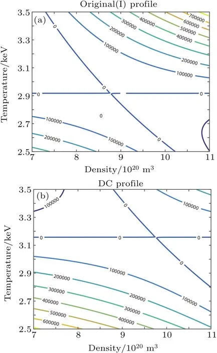
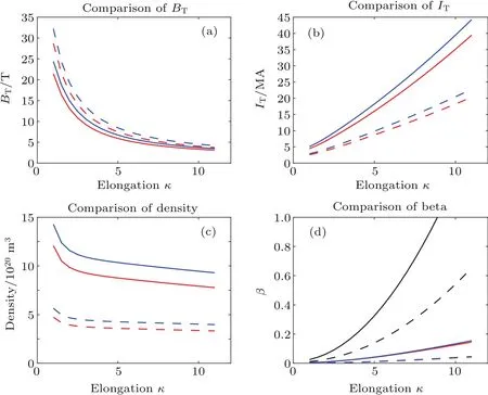
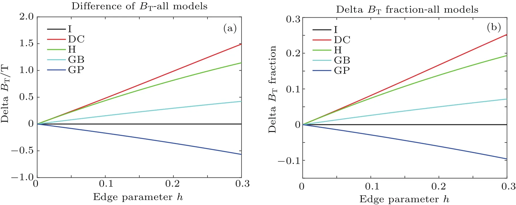
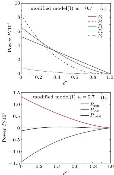
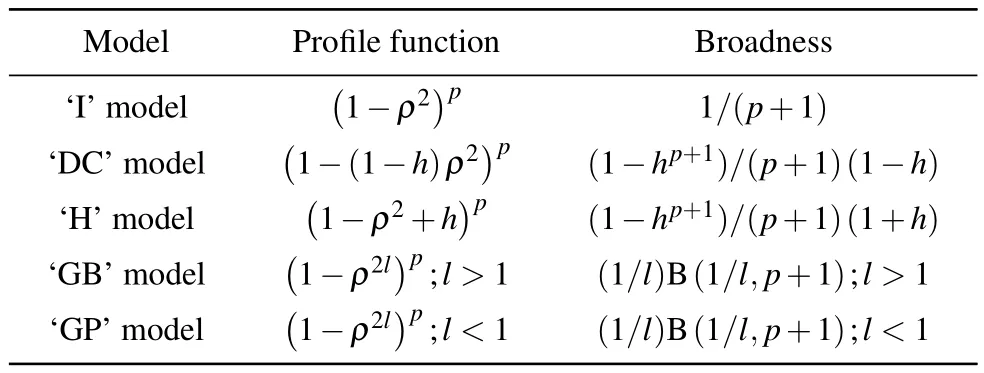
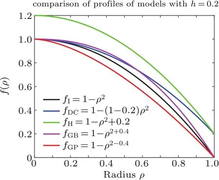
We see that at h=0,fDCreduces to fI(see Eq.(4)).At 0 These averages modify the definitions of the K functions,but do not change the relationship betweenand K.With the modified values of K,we can still use the same method outlined in Section 2 to obtain the expressions for the various quantities at ignition,i.e.,the formulae are the same,although their numerical values have changed,because the values of K have changed,thus thehave changed. The results of our study indicate that with fDCtype of profile,the resultant BTis always larger than that of the original fIprofile.We show in Fig.1 the comparison of the saddle point structure of the averaged power in the(n T)plane.Figure 1(a)shows the contour of averaged power of original profiles using fI; figure 1(b)displays the averaged power for a plasma with an fDCtype of edge barrier with ‘h=0.2’.We observe that the edge pedestal moves the ignition point towards higher averaged density and higher averaged temperature. Fig.1.(a)Original profile ‘I’model and(b)discharge cleaning profile‘DC’model(see Eq.(10))with ‘h=0.2’,showing that bothare shifted to higher values in ‘DC’profile than in ‘I’profile. In the H mode,the plasma develops an edge transport barrier which propagates into the center of the plasma.This results[7]in an improved overall plasma confinement.A simplified but useful assumption is made for this model as follows:the whole profile increases by the same amount as the pedestal.This actually also broadens the plasma profile.We can model this type of edge transport barrier as Quite obviously,if h=0,fHdecreases to fI(see Eq.(4)).At h<1,the edge value increases by a value of hp,and the value in the center is(1+h)p.If h=1,the profile does not become a constant as in the case of Subsection 3.1.The profile average of fHis To facilitate our understanding of these two different types of profiles,we show in Fig.2 their comparison with the original profile.It is interesting to note that for fIn=(1−ρ2),br=pk=0.5;for the DC profile with fDCn=(1−(1−h)ρ2),br=0.5(1+h),pk=0.5(1−h);and for the H profile with fHn=(1−ρ2+h),br=(0.5+h)/(1+h),pk=0.5/(1+h).Therefore,the increase in the edge pedestal will always result in a broader profile. The effect of fHtype of profile in affecting various quantities at ignition is shown in Fig.3.The system parameters are the same as those used in Fig.1.Figure 3(a)shows the values of the marginal BT, figure 3(b)the values of the total current IP, figure 3(c)the values of the density,and figure 3(d)the values of averaged β.The red line is for the original case,and the blue line for the case with an H-type edge barrier with‘h=0.2’.The black curves refer to the Troyon β limits.[9] Fig.2.Comparison of the profiles in the ‘I’profile with that in the ‘DC’model and in the ‘H’model.Note that both DC and H models have non-zero values at the edge.Also for H profile,central value exceeds 1.Solid red curves represent density profiles,the dotted blue curves refer to temperature profiles,and green curves indicate current density profiles. Fig.3.Physical parameters at ignition for‘I’model(red)and ‘H’model(blue)for aspect ratio=3(solid)and 7(dashed)plasma versus elongation κ.For‘H’model,h=0.2(see Eq.(12))is used.Panel(a)shows marginal toroidal field BTin unit T,panel(b)exhibits toroidal current IPin MA,panel(c)refers to average densitn 1020/m3and panel(d)indicates volume averaged β values.The black curves represent Tryon limits. We see that both types of edge transport barriers at this modest barrier height result in higher required BT,higher total current,higher density,and higher β value.We believe that this is due to the fact that both types of transport barriers result in broadening the profile. In this subsection,we use an even more extended set of profiles than the ’I’models which are summarized in Section 2 to show that the peakedness of profile will lead to the improvement of ignition condition or the reduction of the toroidal field required for ignition.A broader profile will lead to an increase in the required BT.We consider the following profiles: We note that this set of functions is the same as the original set if l=1.If l>1,then it is broader;if l<1,then it is more peaked.The average of this profile over the plasma cross-section gives Fig.4.Comparisons among variations of marginal BTrequired for all models at ignition relative to the ‘I’model for an aspect ration A=3 plasma,with edge parameter h(see Eqs.(10)and(12)).In order to accommodate all models in the same figure,we also used h to denote l±1.(see Eq.(14))for the ‘GB’(broader)and ‘GP’(more peaked)models.Panel(a)is the change of BTin unit of T,and panel(b)is the change relative to that of the ‘I’model(see Eq.(4)). Fig.5.(a)and(c)Plots of different components of power versus squared minor radius.(b)and(d)total sum of power input,power loss,and net power.Values for standard ‘I’profile are plotted in panels(a)and(b),and values for the ‘H’profile with A=3,κ =5 are plotted in panel(c)and panel(d). or Here,B is the Beta function,i.e., and it is readily evaluated.Therefore,we have the generalized FGfunction as given below. We note that this generalization of the profile function is different from that of the pedestal function introduced in Subsections 3.1 and 3.2,shown in Fig.4 is the comparison of the effect among the different models defined up to now in affecting the marginal BTas a function of the barrier height h.It is seen that if the barrier height is increased, then the marginal BTis raised;similarly,if the profile is broader,then the marginal ignition BTis raised.Because raising the barrier height is to broaden the profile,we conclude that,in general,broadening the profile leads to raising the BTand vice versa.We attribute this to the fact that most of the fusion power input required for the ignition is located in the center of the plasma. Figure 5 shows the distributions of various components of power generation(loss)versus variable ρ2.It is clear that the fusion power is the most concentrated component in the plasma center.Therefore,as expected,the main cause of ignition is due to the fast rise of fusion power production near the plasma center which keeps the central temperature rising,and eventually leads to ignition.Raising the edge density and temperature everywhere by the same amount would not be conducible to the ignition.The interesting question is“Can we change the situation if the profile of fusion power generation is modified?” To further investigate the basic cause of‘failure to reduce the required BTin plasma in which the edge density and temperature are raised’,in this section we introduce a fictitious energy deposition model to clarify this issue. Because we hope to attribute the result to energy production being too concentrated in the center of the plasma,a model in which the energy deposition profile is more flexible should be useful.From Fig.5 we see that only the fusion power is very concentrated in the plasma center,therefore we propose to consider the following modification model for the fusion energy production Here,w represents the replacement of center energy generation by averaged energy generation.It is seen that if w=0,we recover the original distribution of energy generation.Ifw>0,the energy distribution is switched from the central region near the magnetic axis towards the outside;whereas if w<0,the energy generation becomes more concentrated in the plasma center.This modified energy generation can modify only the Kfcoefficients.In this case, With this modified model,when w increases,the minimum BTincreases with w.However,the effect of edge transport barrier on BTis reduced.As a matter of fact,consider specifically the case of w=0.7,then the fusion and the Ohmic power deposition profile will become the same,then increasing the edge pedestal actually becomes favorable.At this time the power balance as a function of volume becomes more favorable at the mid portion of the plasma,and unfavorable in the center.The various components of the energy deposition profiles for w=0.7 are shown in Fig.6.With this value of w,we should expect the edge barriers to have a reduced BTfor the‘DC’and‘H’model relative to the ‘I’model. Fig.6.(a)Different components of power versus squared minor radius for modified fictitious plasma ignition model with w=0.7(seeEq.(17))profile with A=3,and κ=5;(b)total sum of power input,power loss,and net power.By comparing with Fig.5,we see that the fusion power input is now the same as the Ohmic power input,and less peaked than the Bremsstrahlung or the ion loss.Also the net power is not peaked in the center but in the mid-range of plasma radius.At this time,the edge pedestal leads to a reduced required BT. Figure 7(a)shows the plots of BTrequired for ignition versus fusion redistribution parameter w for the various models.We can see that as expected,when the fusion power becomes less peaked in the center,the required toroidal fields all increase.Figure 7(b)shows the plots of the required BTrelative to the original model versus fusion redistribution parameter w.We can see that as expected,when w increases,the required BTvalue for each of the ‘DC’and ‘H’model gradually becomes smaller.At the same time,the BTfor model‘GB’also becomes smaller,while that of model‘GP’becomes larger than that of the original model.As expected,the values of BTand delta BTchanging over actually occur at w=0.45 before reaching w=0.7. Therefore we conclude that the counter intuitive effect of the edge pedestal on the required minimum BTis due to the fact that the fusion power deposition is extremely concentrated in the plasma center. Fig.7.(a)Plots of BTrequired versus fusion power redistribution parameter w for various models,showing that as the fusion deposition power moves away from the center,the required BTincreases for all models.(b)Plots of difference in required BTrelative to that of the original model used in Ref.[4],versus fusion power redistribution parameter w,indicating that as w increases,values of required BTfor‘DC’,‘H’,and ‘GB’models are all improved with respect to those of original model and ‘GP’model becomes less favorable.The values of BTand delta BTchanging over actually occur around w=0.45 before reaching 0.7. Ohmic ignition remains an attractive option to achieve ignition in fusion devices.[6]The major challenge is the large toroidal field required.It was proposed in a previous research[4]that this major difficulty could be circumvented by using an elongated tokamak.The plasma profiles employed in the previous study did not include the presence of a transport barrier.In this work,we examined a wide class of different profiles,including the possibility of a transport barrier as shown in Table 1. The comparisons among different types of profiles are shown in Fig.8. We found that broader profiles would lead to higher BT:more peaked profiles would lead to smaller values of BT.This phenomenon is not restricted to whether or not an edge transport barrier exists.We also generalize the ignition problem to the case where there are different fusion energy deposition profiles,and show that the relationship between the required BTand the profile peakedness is a direct consequence of the fusion power generation concentrating near the plasma center.When a sufficient amount of fusion power generation is moved away from the plasma center towards the outer parts of the plasma radius,an edge transport barrier then leads to a reduced BTrelative to profile without a barrier.However,moving the fusion power away from the center,in general,leads to a higher BTregardless of profile models.Only when the power input becomes less concentrated at the plasma center,then the transport barriers show advantages with respect to profiles without a transport barrier. Table 1.Profiles and broadness for various models. Fig.8.Comparisons among different plasma profiles studied with h=0.2 and l=1+h=1.2 for GB model and l=1+h=0.8 for GP model. This work was done on the ShenMa High Performance Computing Cluster at the Institute of Plasma Physics,Chinese Academy of Sciences. [1]Li J G 2016 Physics 45 88(in Chinese) [2]Coppi B 1977 Comments Plasma Phys.Control.Fusion 3 47 [3]Wagner C E 1981 Phys.Rev.Lett.46 654 [4]Chu M S,Harvey R W,Politzer P A and Yamagishi T 1985 Nucl.Fusion 25 835 [5]Cohn D R and Bromberg L 1986 J.Fusion Energy 5 161 [6]https://wikivisually.com/wiki/Ignitor [7]Wagner F,Fussmann G,Grave T,et al.,1984 Phys.Rev.Lett.53 1453 [8]Behn R,Alfier A,Yu S,Zhuang G,Pasqualotto R,Nielsen P,Martin Y and team T C V 2007 Plasma Phys.Control.Fusion 49 1289 [9]Troyon F,Gruber T,Saurenmann H,Semenzato S and Succi S 1984 Plasma Phys.Control.Fusion 26 1A 209
3.2.H mode-induced edge transport barrier


3.3.Effects of more general types of profiles(broader or more peaked)on marginal BBBTTT




4.Effects of modified energy deposition profile



5.Summary and conclusions
Acknowledgment
猜你喜欢
杂志排行
Chinese Physics B的其它文章
- Effect of carrier mobility on performance of perovskite solar cells∗
- Plasma electrolytic liquefaction of sawdust∗
- Insight into band alignment of Zn(O,S)/CZTSe solar cell by simulation∗
- Effect of terahertz pulse on gene expression in human eye cells∗
- Ultraviolet photodetectors based on wide bandgap oxide semiconductor films∗
- A primary model of decoherence in neuronal microtubules based on the interaction Hamiltonian between microtubules and plasmon in the neurons
