Adaptive fault-tolerant attitude tracking control for spacecraft with time-varying inertia uncertainties
2019-04-02QingleiHULiXIAOChenlingWANG
Qinglei HU,Li XIAO,Chenling WANG
aSchool of Automation Science and Electrical Engineering,Beihang University,Beijing 100191,China
bSino-French Engineer School,Beihang University,Beijing 100191,China
KEYWORDS Adaptive control;Attitude tracking;Changing center of mass;Fault-tolerant;Spacecraft
Abstract This paper is devoted to adaptive attitude tracking control for rigid spacecraft in the presence of parametric uncertainties,actuator faults and external disturbance.specifically,a dynamic model is established based on one-tank spacecraft,which explicitly takes into account changing Center of Mass(CM).Then,a control scheme is proposed to achieve attitude tracking.Bene fi ting from explicitly considering the changing CM during the controller design process,the proposed scheme possesses good robustness to parametric uncertainties with less fuel consumption.Moreover,a fault-tolerant control algorithm is proposed to accommodate actuator faults with no need of knowing the actuators'fault information.Lyapunov-based analysis is provided and the closed-loop system stability is rigorously proved.Finally,numerical simulations are presented to illustrate the effectiveness of the proposed controllers.
1.Introduction
The computation method of unsteady transonic flow based on N-S equationsshould bebestaccurate,butto threedimensional complex problems,it can be achieved only on large computers,and moreover,the results are not ideal sometimes.1A viscous/inviscid interaction method is an applicable one and the computation time can be reduced by two orders.
Attitude tracking is a fundamental mission that most spacecraft must perform during their operations and this issue has been extensively studied in the existing literatures.1-3In particular,adaptive control techniques have been largely applied to addressing the problem of unknown or uncertain system parameters.4-7However,the majority of available adaptive attitude tracking control solutions do not consider the changing Center of Mass(CM)caused by fuel consumption.The fuel often provides a significant contribution to the overall mass of the spacecraft to execute station keeping and attitude maneuvering.Therefore,the effect of fuel consumption is important for the determination of CM for the spacecraft.And the changing CM can result in variant body- fixed coordinate frame and time-varying inertia profile,which may degrade the control accuracy or even destroy the system stability.Moreover,fault-tolerant capacity is also required for spacecraft because actuator faults are frequently encountered in practical spacecraft operations.All the above issues create considerable difficulty in the design of attitude control algorithms for achieving accurate,reliable and fast responses,especially when these issues are treated simultaneously.
The effect of changing mass properties for spacecraft has been addressed in some of the existing literatures.The interactionsamongthefuelslosh,theattitudedynamicsandthe flexible appendages havebeenstudied inRef.8viaa classical multi-body approach.Jing et al.9proposed a switching attitude control law by considering the astronomy observation satellite with the sensor of non-negligible mass and length.A robust controller has been designed in Ref.10to deal with the position changes of CM due to fuel consumption for the micro-satellite.Deng and Yue11focusedonthenonlinearlymodellingandattitudedynamics of spacecraft coupled with large amplitude liquid sloshing dynamics and flexible appendage vibration and designed a feedback controller for the attitude maneuvering problem.
Another key issue related to spacecraft attitude control involves actuator faults.In practice,actuator faults are frequently encountered due to the harsh working environment.The occurrence of actuator faults might result in mission failure and even system instability.Thus,extensive fault-tolerant control schemes have been carried out for the spacecraft attitude control in the previous literatures.Fuzzy logic has been applied12-14to design fault-tolerant controllers of the spacecraft.Xiao et al.15proposed an SMC-based fault-tolerant attitude-tracking control approach with the capability of finite-time convergence with zero tracking error.A faulttolerant control algorithm relying on an ideal reference model has been presented.16Based on variable structure control,a fault-tolerant tracking control scheme without any requirement of fault identi fi cation has been developed.17Shen et al.proposed a fault-tolerant control law using the control allocation approach to deal with the actuator faults.18In Ref.19,the integral-type sliding mode control has been employed in the design of the fault-tolerant control algorithm against actuator stuck faults for spacecraft attitude maneuvering.
Although significant studies have been conducted to deal with the changing mass properties and the actuator faults,to the best of our knowledge,few of them have treated the changing CM(caused by the mass variation)and actuator faults simultaneously.However,these problems are very likely to happen simultaneously in practical situations,which may degrade the control performance or even result in mission failure.Therefore,it is crucial to take these problems into consideration during the controller design process.In this paper,an adaptive fault-tolerant control scheme is developed to address the spacecraft attitude tracking problem under inertia uncertainty,actuator faults and external disturbance.Based on a one-tank spacecraft,an explicit dynamic model of the timevarying inertia matrix is established,and it is taken into account both in the dynamic equations of the spacecraft and controller design process.The main contribution of this work includes two parts:(A)characterize the time-varying inertia dynamic model with consideration of changing CM to construct the adaptive attitude tracking controller.Hence,the time-varying inertial parameters will not introduce important influence on the control performance with the proposed control scheme;(B)propose an adaptive fault-tolerant control algorithm which can achieve high-precision attitude tracking,despite the presence of time-varying inertia properties,external disturbances and actuator faults(including total failures).The system stability is also rigorously analyzed through Lyapunov analysis.
The rest of the paper is organized as follows.The mathematical model of a spacecraft with time-varying inertia matrix and the characterization of the time-varying inertia matrix are derived in Section 2.The next section presents the design procedure and stability analysis of the control algorithm.Numerical simulations are provided in Section 4 to demonstrate the performance of the proposed control scheme.Finally,the paper is completed with some concluding comments.
Notation.Through this article,Rnis the n-dimensional Euclidean space,and Rn×mrepresents the set of all real matrices of dimension n×m.The skew-symmetric matrix operator S(·)represents the vector cross-product operation between any two vectors,de fined by S(a)b=a×b for any a,b∈R3.MTis the transpose of M.diag(x1,x2,...,xn)denotes the diagonal matrix of dimension n×n with diagonal elements x1,x2,...,xn.λmin(M)and λmax(M)are the maximum and minimum eigenvalues of M.|·|and‖ · ‖stand for the usual L1and L2norms.
2.Problem statement and preliminaries
2.1.Spacecraft dynamics
The governing equations for attitude motion of a spacecraft are formulated in terms of the unit-quaternion representation.The attitude kinematics are given by20:

where the unit-quaternion q=[q0,qTv]T∈R4(q0(t) ∈R and qv(t) ∈R3are the scalar and vector parts of q respectively)denotes the attitude orientation of the body- fixed frame B with respect to the inertial frame N,and satisfies the constraint qTq=1;ω∈R3denotes the inertial angular velocity of the spacecraft expressed in B;I is the 3×3 identity matrix.The corresponding attitude dynamics are written as6

where J(t) ∈R3×3is the time-varying inertia matrix of the spacecraft,and remains symmetric positive-definite for all time;τ(t) ∈R3is the control torque input generated by the torque actuators;d(t) ∈R3is the external disturbance.The direction cosine matrix,denoting a transformation from N to B,can be calculated by

Since the desired reference angular velocity is specified in its own reference frame R,the rotation matrix from R to B can be obtained as


where φ=S(ωe)C(qe)ωr-C(qe)˙ωrand we note hereafter Q=0.5(qe0I+S(qev)).
The control objective of this paper is to design an adaptive fault-tolerant attitude tracking controller for the spacecraft subject to time-varying inertia matrix,external disturbances and actuator faults so that all closed-loop signals are uniformly bounded and that the attitude tracking errors converge to a small set around the origin.To this end,the following assumption is made13,15,18:
Assumption 1.The external disturbance d is bounded by‖d‖≤dm,where dm>0 is an unknown constant.
2.2.Characterization of time-varying inertia matrix with changing CM
Generally speaking,our system consists of a rigid spacecraft body with CM initially located at point O(the initial CM,remains fixed to the spacecraft body)and a fuel tank that is offset from point O by a distance of rfin the x-direction.As shown in Fig.1,the body- fixed frame B remains fixed at the CM and rotates with the spacecraft.The origin Obis located at the CM,the x-axis,xb,is directed from Obto the fuel tank,the z-axis,zb,is the initial spin axis,and the y-axis,yb,completes the body- fixed coordinate system.
In this paper,both the fuel tank and the mass-invariant part are modeled as mass points,using the solving equation for CM of a mass point system rσ=Pimir/Pimi,where rσis the position vector of the system's CM relative to a fixedpoint;miand riare the mass and position vector relative to the same fixed-point of the ith mass point.Then,we can deduce the position vector r(t)of the instantaneous CM relative to O as

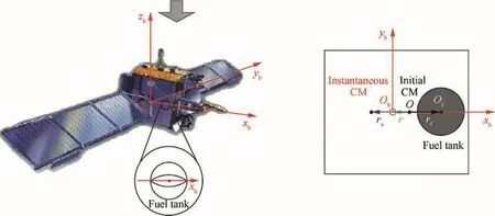
Fig.1 Body- fixed coordinate frame.
where m0is the total mass of all the mass-invariant parts,rsis the position vector of m0relative to O,m(t)denotes the mass of the remaining fuel at time t,and rfrepresents the position vector of the fuel tank relative to O.By Definition that r(t)hasan initialvalue ofzero,r(0)=0,we can obtain rs=-m(0)rf/m0.Applying this result to Eq.(7),the CM vector can be found by

De fine the time-varying inertia matrix as

where J(0)is the inertia matrix at t=0,and J011,J022and J033are unknown constants.Using the parallel axis theorem to account for the changing CM location,and considering the fuel consumption,the time-varying inertial matrix at time t can be expressed as21Then,expanding and rearranging Eq.(9),the inertia matrix can be expressed as


where J0=diag(J011,J022-m(0)r2f,J033-m(0)r2f)is a constant matrix with unknown parameters

is a known and time-dependent matrix;J1=diag(0,1,1).By differentiating Eq.(10)with respect to time,we thus have

The rate of change of the fuel mass is known to be a function of the applied control and actuator hardware characteristics,so that we use the mass relation6

where c>0 is a known constant.
Then,by taking the time derivative of Ψ(t)and applying Eq.(12),it follows that

where mi=m(0)+m0is the initial mass of the spacecraft without any fuel consumption.
Remark 1.For the characterization of the inertia matrix,we not only consider the direct influence of the fuel consumption,but also explicitly take into account the impact of the changing CM caused by the fuel consumption.Thus,a more accurate spacecraft dynamic model is obtained.
3.Adaptive controller design
In this section,an adaptive attitude tracking control strategy is presented to solve the current problem under study.We start by synthesizing a basic adaptive controller for the case in which all the actuators work healthily to help illustrate the key idea of accounting for the time-varying inertia properties.The result is then extended to an adaptive fault-tolerant control synthesis.
3.1.Basic adaptive controller design
Substituting Eqs.(10)and(11)into Eq.(6),the angular velocity error dynamics can be rewritten as

where H1=-S(ω)J1Ψω+J1Ψφ,and the regressor matrix W1is constructed in the following fashion:

with θ=[J011,J022,J033]Tcontaining the three elements of J0.
To develop the control scheme,we de fine the fi ltered error variable

where β>0 is a design parameter.Then,we design the adaptive controller and the accompanying adaptive law as

with
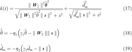
where k1>0 is a control gain,Ω=ω-(s/2),W2is a known regressor matrix satisfying W2θ=W1θ+βJ0Qωe,H2=H1+β(J1ΨQωe+qev),^¯θ and^dmare the estimations ofand dm,respectively,and both ηiand γi(i=1,2)are positive design constants.
Theorem 1.Considerthe attitude tracking errorsystem described by Eqs.(5)and(6)with time-varying inertia matrix characterized by Eqs.(10)-(13).If the control law in Eq.(16),together with the adaptive laws in Eqs.(18)and(19),is applied,then the closed-loop system is globally stable in the sense that all the signals are continuous and bounded,and the tracking errors qev(t)and ωe(t)converge to a small set containing the origin.
Proof.Consider the following Lyapunov Function Candidat e(LFC):


To proceed,the following key inequality is introduced;specifically,for any scalar ε>0 and x∈R,we have

By applying Eq.(22),one can deduce that

Further,by completion of squares and using Eq.(23)in Eq.(21),it follows that4
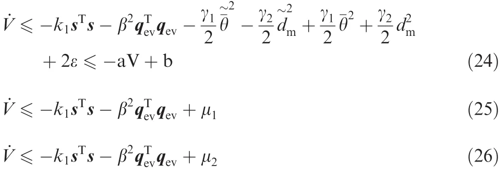
where

Note that Eq.(24)implies that V∈L∞.Then we conclude that and successively.And from Eqs.(25)and(26),one can observe that V˙ <0 when (s,qev) is out of the setb1>b2,the set B1encloses completely the set B2.Therefore,once(s,qev)is inside the set B1,they cannot go out of it because they will be attached back to B2,which means that the states are con fined in the set B1.Furthermore,the boundedness of(s,qev)indicates that ωeis also bounded because of Eq. (15). And its bound can be determined as
Remark 2.The time-varying inertia properties with changing CM are considered both in the construction of spacecraft dynamic model and the controller design process.Thus,the change of CM caused by fuel consumption during the spacecraft on-orbit attitude maneuvers will not have a large effect on the control performance under the proposed adaptive controller.This fact can help improve the attitude tracking ef ficiency and accuracy.
3.2.Adaptive fault-tolerant controller design
It is common practice to equip the spacecraft with three or more than three torque actuators for robustness reasons.From a practical viewpoint,despite various efforts to enhance reliability of the components of the torque actuators,multiple anomalies do occur in them during their long operational life.Thus,it is imperative to develop fault-tolerant control algorithms that are capable of accommodating possible actuator faults for spacecraft attitude tracking control.In view of this,in this subsection,we shall present an adaptive fault-tolerant control architecture with a slight modification to the control scheme presented in Section 3.1.
To describe actuator faults,the control input of dynamic system Eq.(6)is further expressed as

where D∈R3×n(n≥3)is the distribution matrix of the torque actuators; E=diag(e1,e2,...,en) ∈Rn×nwith 0≤ei≤1(i=1,2,...,n)isthe actuation effectivenessmatrix that describes the health condition of the torque actuators;u∈Rnand¯u∈Rndenote the desired control input signals and the unexpected deviation faults,respectively.To proceed,the following assumptions are made.
Assumption 215.The additive bias forces¯u is bounded,and there exists an unknown constant um>0 such that‖¯u‖≤um.
Assumption 3(4,5,18).Assume that the matrix DEDTremains positive definite for all fault scenarios that are under consideration,which indicates that there are at most n-3 actuators that totally fail to work.
By applying Eq.(27),Eq.(14)can be rewritten as

We further have

Choose the smooth control law and the accompanying adaptive laws as
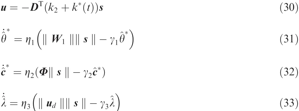
where k2>0 is the control gain,^θ*,^c*and^λ denote the estimations of θ*,c*and λ,respectively,and ηi>0 and γi>0(i=1,2,3)are design parameters.In Eq.(30),the timevarying gain k*(t)is given by

The main result of the paper is summarized as the following theorem.
Theorem 2.Consider the spacecraft attitude dynamics as described by Eqs.(5),(6)and(27).By implementing the proposed control scheme as given in Eqs.(30)-(34),all the closed-loop signals are bounded and the tracking errors qev(t)and ωe(t)converge to a small set containing the origin.
Proof.Consider the following LFC:


Similar to Section 3.1,by applying Eq.(22),we have

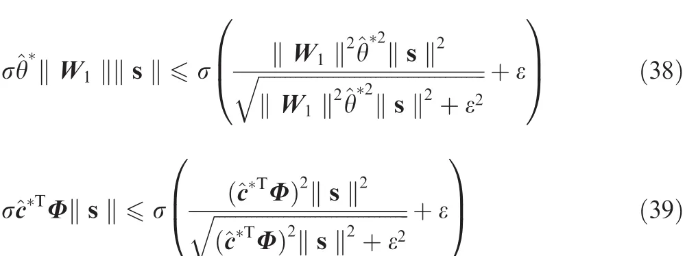
Inserting Eqs.(30)-(34)into Eq.(36)and noting Eqs.(37)-(39),one can easily obtain

Following the similar reasoning as that in the proof of Theorem 1,we further have

Remark 3.The proposed control algorithm can ensure stable attitude tracking,despite the presence of external disturbances,inertia uncertainties,and actuator faults,as long as the matrix DEDTremains positive definite for all fault scenarios that are under consideration.However,it should be pointed out that an implicit assumption is that the remaining active torque actuators under actuation limits are still able to produce suf ficient control torques for spacecraft to perform the given maneuvers.
4.Numerical simulations
To illustrate the effectiveness of the proposed control scheme,numerical simulations are conducted in this section.In the simulation,the value of the inertia component J0is set as

For each set of simulations,the initial attitude of the spacecraft is selected asand the angular velocity isThe desired attitude motion is determined by qr(0)=[1,0,0,0]TandAnd the externaldisturbance istaken asd=0.06[sin(0.8t),cos(0.5t),cos(0.3t)]TN·m.
Consider a case in which six two-sided thrusters with the same nominal maximum thrust capability are symmetrically distributed on three axes of the body frame B of the spacecraft in the configuration presented in Fig.2.Then the distribution matrix can be determined by the distance between the initial CM and the mounting position,and D is expressed as

And we chose d1=0.8 m and d2=d3=0.7 m.The parameters for the characterization of inertia matrix are chosen as c=0.1,rf=0.2 m,m(0)=70 kg and m0=105 kg.Considering the physical performance of the actuators in practical cases,the available actuation is always limited.Therefore,a saturation function is used for the thrusters in the simulations.The saturation values are set as 10 N,i.e.the actual forces generated by the thrusters remain at 10 N when the command signals get over these values.The controller in Eq.(14)and the controller in Ref.6are multiplied by the pseudo-inverse of matrix D to accord the dimension and the units in the numerical simulations.
4.1.Healthy actuators
In this case,all actuators are assumed to work healthily,and the control scheme in Eqs.(16)-(19)is applied.The main control parameters of the proposed controller are determined as γ1=4×10⁻⁶,γ2=0.01,β=0.9,ε=0.002,η1=3,η2=3 and k1=20.
To show the favorable performance of the proposed control algorithm,comparison between the proposed controller and the control law in Ref.6and in Ref.4are presented.For a fair and meaningful comparison,all the controller parameters of Ref.6and Ref.4keep their original values,except that β in Ref.4is chosen as β=1 for fair comparison.The time responses of relative angular velocity error ωeand relative attitude tracking error qevare shown in Fig.3.One can observe that the proposed controller shows better tracking accuracy than the controller in Ref.6,which is more clearly shown by the norms of the tracking errors in Fig.4.The degradation of performance of the control scheme in Ref.6is mainly caused by the CM changes,which are not explicitly taken into account in the controller design of Ref.6.It is also observed from Figs.3 and 4 that the controller in Ref.4can achieve favorable control accuracy at the beginning.However,the tracking errors continue to enlarge while the change of CM increases,which means that the controller in Ref.4has weaker robustness to the time-varying property of CM.In contrast,the changing CM is explicitly taken into consideration during the design process of the proposed control scheme,and thus,the change of CM caused by fuel consumption will not possess an important influence on the control accuracy.The time responses of Euler angles are shown in Fig.5,and it intuitionally presents the tracking process,which is consistent with the results of tracking errors.
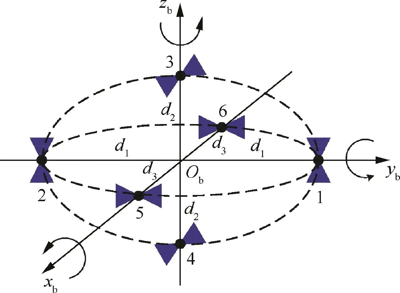
Fig.2 Distribution schematic of six thrusters.

Fig.3 Time responses of angular velocity and attitude tracking errors with healthy actuators.
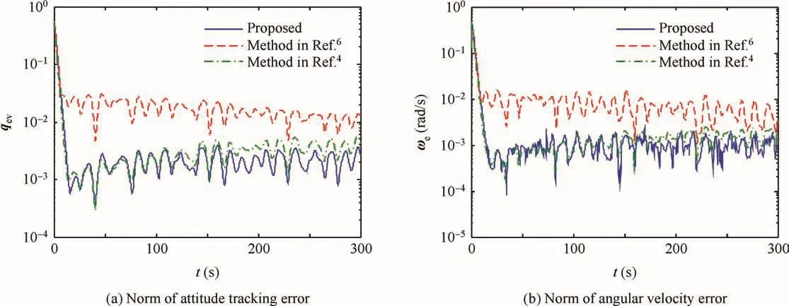
Fig.4 Norms of angular velocity error vector and attitude tracking error vector with healthy actuators.
The control forces produced by the six thrusters are presented in Fig.6.It is observed that the controllers in Ref.6and in Ref.4command a higher control torque than the proposed controller.
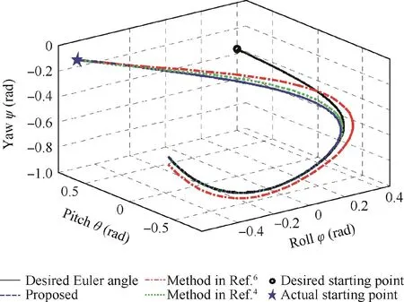
Fig.5 Time responses of Euler angles.

Fig.6 Time responses of control forces with healthy actuators.

Fig.7 Norms of tracking errors and control signals of proposed controller with healthy actuators.
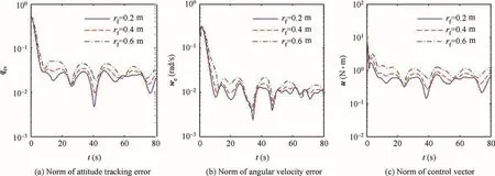
Fig.8 Norms of tracking errors and control signals of controller in Ref.6with different rf.
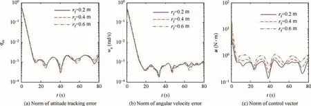
Fig.9 Norms of tracking errors and control signals of controller in Ref.4with different rf.

Fig.10 Comparison of CM variation.

Fig.11 Comparison of fuel consumption for t=300s with healthy actuators.
For the purpose of verifying the robustness of the proposed controller to various changing velocity of CM,we change the value of rfto 0.4 m and 0.6 m,because larger rfcan generate a faster and larger variation of CM as the fuel is consuming.It is clear from the results of Fig.7 that although the faster variation of CM slightly reduces the convergence rate of the proposed control scheme,the high attitude tracking accuracy is almost not affected.And a larger control effort is required for the faster variation of CM.The norms of angular velocity,attitude tracking error and control vector with the controller in Ref.6are illustrated in Fig.8.It is observed that the controller in Ref.6suffers from lower accuracy for both attitude and angular velocity tracking due to faster variation of CM,and larger control effort is also demanded.
And Fig.9 shows that the controller in Ref.4also possesses good robustness to different changing velocities of CM.The results in Fig.9 and in Fig.4 indicate that different changing velocities of CM almost do not affect the control performance of the controller in Ref.4but the time-varying properties of CM produce a degradation of control accuracy.
In Figs.10 and 11,it can be seen that the controllers in Ref.6and in Ref.4command higher fuel consumption and thus there is a larger change of CM than the proposed controller for the same rfand the difference increases when rfbecome larger.The higher fuel consumption stems from the fact that the controllers in Ref.6and in Ref.4do not directly take into account the changing CM.
4.2.Faulty actuators
Next,simulations are conducted for the case where the spacecraft is subject to actuator faults.The effectiveness matrix E(t)is generated by the following equation:


Fig.12 Effectiveness factors.
where rand(·) ∈ (-1,1)is a random number generator,and the sampling time is T=13 s ti=mod(t+Δti,T),Δti=2(i-1),i=1,2,...,6.The additive fault¯u is de fined as=0.003[ sin(0.03t),sin(0.05πt),cos(0.15t),sin(0.03πt),

The control scheme in Eqs.(30)-(34)is applied and the control parameters are given as β=0.9,k2=30,ε=0.09,η1=200,κ1=3×10⁻⁴,η2=102,κ2=0.015,η3=100 and κ3=0.001.
Comparison between the proposed controller and those of Ref.6and Ref.4is also given in this subsection,and β in Ref.4is given as β=1.6 for fair comparison.The effectiveness factors of the six actuators are shown in Fig.12.Note that the actuators 2,4 and 6 are shuttled down on purpose at time 11 s,15 s and 19 s respectively.
The angular velocity and attitude tracking errors are presented in Fig.13 and the norms are shown in Fig.14.One can observe that the control scheme in Ref.6cannot achieve satisfactory tracking accuracy anymore due to the actuator faults.In contrast,high control precision is still obtained with the proposed controller.In spite of the reliability of the controller in Ref.4,it still suffers from loss of accuracy as the CM changes.
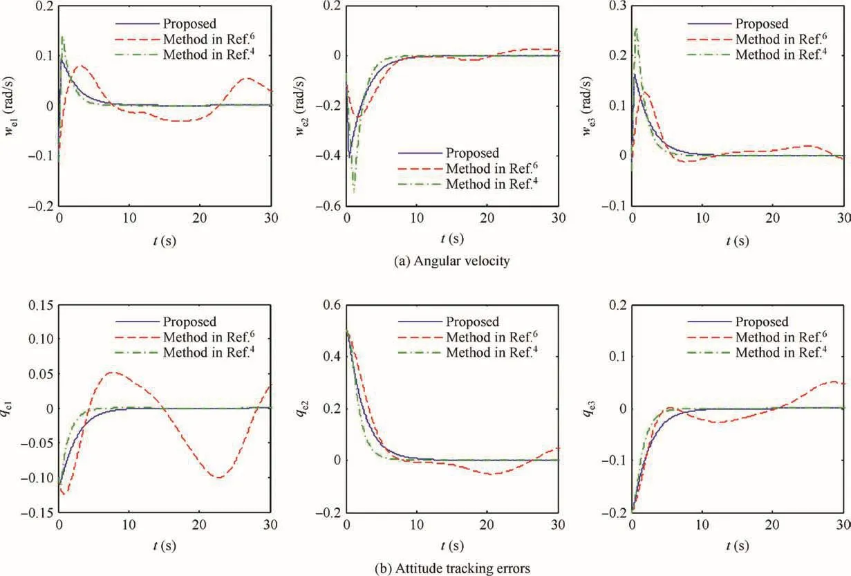
Fig.13 Time responses of angular velocity and attitude tracking errors.
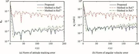
Fig.14 Norms of angular velocity error vector and attitude tracking error vector with faulty actuators.
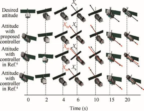
Fig.15 Snapshots of attitude orientation history.
To illustrate the tracking process,a series of snapshots of the actual attitude orientations of four spacecraft with the desired attitude,the attitude generated by the proposed controller and the attitude generated by the controllers in Ref.6and in Ref.4are shown in Fig.15.The x-axis of the bodyfixed frames,xbp,xb,xb6and xb4,are identified for the spacecraft(the black dotted lines parallel to xbare constructed to illustrate the attitude tracking errors).
It is observed that the spacecraft controlled by the proposed controller and the controller in Ref.4show almost the same performance to the desired attitude from t=6 s.In contrast,there is always a significant distinction between the attitude of the spacecraft controlled by the controller in Ref.6and the desired attitude.

Fig.16 Time responses of control forces with faulty actuators.
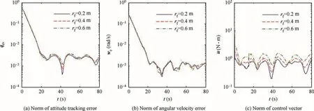
Fig.17 Norms of tracking errors and control signals of proposed controller with faulty actuators.

Fig.18 Norms of tracking errors and control signals of controller in Ref.6with different rf.

Fig.19 Norms of tracking errors and control signals of controller in Ref.4with different rf.
The control forces of the thrusters are shown in Fig.16.One can observe that the control law in Ref.6commands a minor control input in the initial transient regime.However,for the steady-state regime,it demands a larger control effort than the proposed controller and the controller in Ref.4,which is more clearly shown by the variation rate of CM and the quantity of fuel consumption in Figs.20 and 21.
Then,we change the value of rfto 0.4 m and 0.6 m,and the results are illustrated in Figs.17-19.It is shown that in the case of actuator faults,although the control accuracy is slightly affected by different changing velocities of CM,the proposed controller and the controller in Ref.4still hold good robustness to different changing velocities of CM.

Fig.20 Comparison of CM variation.
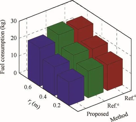
Fig.21 Comparison of fuel consumption for t=300s with faulty actuators.
5.Conclusions
This paper investigated the fault-tolerant attitude tracking control problem for a rigid spacecraft in the presence of external disturbance,actuators faults and time-varying inertia matrix.Changing CM has been directly taken into account during the characterization of the time-varying inertia matrix.Firstly,a basic controller is designed to deal with the attitude tracking mission without actuator fault.Then,two types of actuator faults(effectiveness loss and additive fault)are considered simultaneously,and an auxiliary controller is designed to deal with the actuator faults.The performance of the proposed controller,as well as the necessity of considering the changing CM during the controller design,is illustrated in the numerical simulations.The proposed control algorithm possesses high control accuracy,fault-tolerant capacity and favorable robustness to time-varying inertial parameters.The time-varying part in inertia matrix is modeled as a known parameter with some reasonable simpli fi cations of the system in this paper.However,it is more interesting to consider unknown time-varying parameters in inertia matrix to release some assumptions of the system,which is one of the subjects for our future research.
Acknowledgement
This work was supported partially by the National Natural Science Foundation of China(Nos.61522301,61633003).
杂志排行
CHINESE JOURNAL OF AERONAUTICS的其它文章
- Efficient multi-response adaptive sampling algorithm for construction of variable- fidelity aerodynamic tables
- Numerical and experimental investigation into hypersonic boundary layer transition induced by roughness elements
- Aerodynamic characteristics of rigid coaxial rotor by wind tunnel test and numerical calculation
- An innovative study on low surface energy micronano coatings with multilevel structures for laminar flow design
- Non-affine parameter dependent LPV model and LMI based adaptive control for turbofan engines
- Vee-tail conceptual design criteria for commercial transport aeroplanes
