Large borehole with multi-lateral branches: A novel solution for exploitation of clayey silt hydrate
2019-01-13YnlongLiYizhoWnQingChenJixinSunNengyouWuGoweiHuFulongNingbPeixioMo
Yn-long Li, Yi-zho Wn, Qing Chen,*, Ji-xin Sun, Neng-you Wu, Go-wei Hu,Fu-long Ningb,, Pei-xio Mo
a Key Laboratory for Natural Gas Hydrate of Ministry of Natural Resources, Qingdao Institute of Marine Geology, China Geological Survery, Ministry of Natural Resources, Qingdao 266071, China
b Laboratory for Marine Mineral Resource, Pilot National Laboratory for Marine Science and Technology, Qingdao 266071, China
c Faculty of Engineering, China University of Geosciences, Wuhan 430074, China
Keywords:
Natural gas hydrate
Clayey silt
Multi-lateral branches
Stimulation
Numerical simulation
Hydrate exploration engineering
South China Sea
China
A B S T R A C T
Raising the in situ decomposition rate of natural gas hydrate and increasing the decomposition contact area are two main ways to raise the productivity of hydrate.An exploitation technique based on large borehole with multi-lateral branches (LB & MB) was proposed in this paper.This technique is mainly intended for the clayey silt hydrate reservoir in the South China Sea, and its main purpose is to alleviate the sand output from formation for maintaining the stability of the reservoir and to greatly increase the gas productivity of the reservoir.In this paper, the following aspects were mainly expounded: definition of the basic geometric parameters for layout of multi-lateral branches in clayey silt hydrate reservoir, simulation of the stimulation effect of a typical well profile with two branches, and prediction and simulation of the reservoir failure risk in a well profile with eight branches.The results show that the LB & MB effectively improves the flow field in the formation, raises the productivity of the reservoir and may also help to decrease the produced water-gas ratio (WGR).When the lateral branches spacing is too small, the failure zones around adjacent lateral branches overlap each other, possibly causing reservoir failure in a larger range.Therefore, the geometric parameters of multi-lateral branches depend on the dual control of the productivity and geotechnical risk factor of reservoir.Further study is being carried out, so as to obtain the optimal combination of parameters of multi-lateral branches.
1.Introduction
Natural gas hydrate, as a kind of novel, efficient and environment-friendly substitute energy, is widely distributed in continental permafrost zones and seafloors along continental margins (Kvenvolden KA, 1995; Boswell R,2007; Chong ZR et al., 2016).At present, universally recognized exploitation methods for hydrates mainly include depressurization (Feng JC et al., 2016), heat injection(Fitzgerald GC et al., 2013; Li G et al., 2010), and carbon dioxide replacement method (Stanwix P et al., 2018), as well as combinations of the above single methods (Moridis GJ et al., 2007; Reagan MT et al., 2015; Li YL et al.2016).The depressurization has been demonstrated to be the most effective exploitation method by field production tests(Heeschen KU et al., 2016; Li JF et al., 2018; Ye JL et al.,2018).However, depressurization certainly will relate to the diffusion process of bottom hole pressure towards hydrate reservoirs.Further hydrate decomposition process will be promoted only if the down hole pressure drop is propagated to the hydrate decomposition front (Liu CL et al., 2017; Wu NY et al., 2018).Therefore, the increase in bottom hole pressure drop may have some siginificant effect in promoting gas productivity.Nevertheless, too large production pressure drop is bound to cause engineering problems such as borehole collapse, and severe sand production (Uchida S et al., 2016;Sun JX et al., 2016, 2018).
The hydrate reservoir in the northern South China Sea is dominated by clayey silt or silty clay, and the medium grain size of the reservoir sediments is less than 20 μm (Zhang RW et al., 2018), it is a typical pore-filling hydrate reservoir with extremely low permeability, mostly less than 20 mD (Chen F et al., 2010; Gao HY et al., 2012; Su PB et al., 2017; Xue H et al., 2016; Zhang W et al., 2017).How to raise the productivity of a reservoir and to effectively alleviate geotechnical risk is the main difficulty countered during hydrate exploitation in silt reservoirs (Wu NY et al., 2017).From the perspective of increasing productivity, increasing the in situ hydrate decomposition rate and enlarging the hydrate decomposition area are two basic ways to raise the single-well productivity.Theoretically, increase in bottom hole pressure drop can achieve the purpose of increasing the in situ hydrate decomposition rate.However, the strength of hydrate reservoir is relatively low, blindly increasing the production pressure difference cannot raise the productivity effectively,but may cause overall collapse of wellbore, destructive sand influx from formation (Li YL et al., 2017a; 2019), or overall reservoir failure (Yoneda J et al., 2015; Wan YZ et al., 2018),resulting in sand burial of borehole.Therefore, enlarging the decomposition area is an effective alternative to increase the gas production capability, and to alleviate the geotechnical problems caused by excessive pressure drop.
Consequently, the team from Qingdao Institute of Marine Geology proposed a novel exploitation technique named large borehole with multi-lateral branches (LB & MB) combined moderate sand control exploitation technique (invention patent number: CN106761587B; international patent classification index number: pct110790).The basic thoughts of this method are as follows: Establish a vertical or horizontal main well, with large-diameter borehole, passing through the hydrate reservoir first, and then drill a number of lateral branches around the main borehole, which exhibit a given included angle with the main borehole and are distributed directionally.Furthermore, all lateral branches are filled will gravel packs to maintain the stability of the highpermeability channels, as well as to achieve the dual goals of raising the gas production capability and reducing the geotechnical risk.In this paper, clayey silt hydrate reservoir in the northern South China Sea was taken to carry out the case study.Recent progresses on this new technology were expounded, which mainly focused on the well profile parameters determination, stimulation effects analysis, and geotechnical risk assessment.
2.Basic well profile parameters and coordination relationships among main borehole and lateral branches
The LB&MB combined moderate sand control exploitation technique is intended to achieve the dual goals of raising the gas production capability and reducing the geotechnical risk.Compared with conventional single-well depressurization method based on vertical well or horizontal well, this exploitation technique has the following main action mechanisms in a clayey silt hydrate reservoir: (1) Wide-area surface effect, that is, effectively increase the hydrate decomposition contact area, forming group-well effect, to further speed up the hydrate decomposition; (2) Change the fluid flow behaviour in the reservoir, the multi-lateral branches and main borehole forming dual high-speed channels for pressure transmission.Thus, the radial flow around a vertical or horizontal well turns into quasi-bilinear flow.This will effectively decrease the pressure drop gradient in the decomposing zone and slow down the sand influx from formation (Li MZ et al., 2014); (3) High-permeability channels for pressure transmission are formed in the packed layers in the lateral branches, to raise the pressure transmission efficiency; (4) The multi-lateral branches are densely packed with gravel, which will benefit the stability of the reservoir to a great extent, in addition to sand prevention.
The basic model in LB & MB can be viewed as“paralleled multi-lateral branches cascade with a main borehole”.There are mainly four basic coordination relationships between the main borehole and the multi-lateral branches,namely, “vertical main borehole perpendicular to (⊥) multilateral branches”, “horizontal main borehole ⊥ multi-lateral branches”, “vertical main borehole obliques from (∠) multilateral branches”, and “horizontal main borehole ∠ multilateral branches” (Fig.1).The advantage of “vertical borehole⊥ multi-lateral branches” layout is that it is capable of accurately controlling the hydrate decomposition processes in different sub-layers, so this layout model is specially suitable for a reservoirs with high vertical heterogeneity of hydrate distribution, and it can slow down the reservoir failure risk via an optimized lateral branches layout in different hydratebearing intervals.
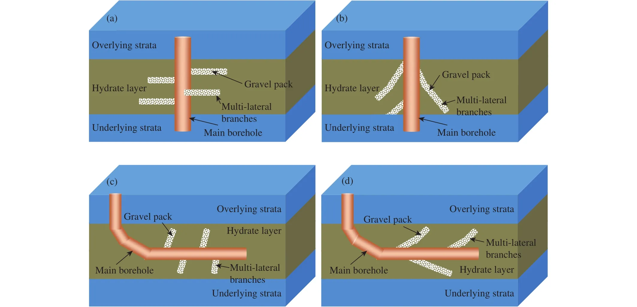
Fig.1.Schematic diagram of LB & MB layouts.a-Vertical main borehole⊥multi-lateral branches; b-vertical main borehole∠multi-lateral branches; c-horizontal main borehole⊥multi-lateral branches; d-horizontal main borehole∠multi-lateral branches.
The key for carrying out efficient exploitation of a clayey silt hydrate reservoir is to determine the optimal combination of geometric parameters of multi-lateral branches.Geotechnical characteristics of hydrate reservoir, construction difficulties during drilling and completion, and the stimulation effect should be taken into comprehensive consideration during geometric parameters optimization.The geometric parameters relating to multi-lateral branches mainly include the phase angle, the dip angle, the lateral branches spacing,the diameter, and the horizontal displacement of the lateral branches (Fig.2).The first step to optimize the geometric parameters of multi-lateral branches is to establish constraint equations among the above geometric parameters of multilateral branches (Gao DL et al., 2007).The geometric parameters of multi-lateral branches were defined specifically in this paper.
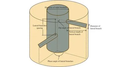
Fig.2.Schematic diagram for explanation of morphological parameters of multi-lateral branches.
Dip angle of lateral branches (α): The included angle between the central axis of main borehole and that of each of multi-lateral branches is defined as dip angle of lateral branch.The dip angle of each lateral branch is 90° in the “vertical main borehole⊥multi-lateral branches ” and “horizontal borehole⊥ multi-lateral branches” layouts.While that in the“vertical borehole ∠ multi-lateral branches” and “horizontal borehole∠ multi-lateral branches” layouts, the dip angle ranges from 0° to 90°.
Phase angle of lateral branches (β): Given a reference plane that is perpendicular to the axis of the main borehole,the included angle between the projection lines (on the reference plane) of the axes of two adjacent lateral branches is defined as phase angle of lateral branches.
Lateral branches spacing (d): Each axes of the multilateral branche intersect with the axis of the main borehole,and the distance between the intersections formed by two adjacent lateral branches and the main borehole is defined as lateral branches spacing.The number of lateral branches within per 10 m of the main borehole is defined as lateral branch density (“holes/10 m”).
Measured depth of lateral branch (Lm): The length of coiled tubing needed for drilling one of the multi-lateral branches is the measured depth of lateral branch, which is measured starting from the wall of the main borehole.
阅读推广视角下的品牌独特性应该是指品牌给予读者的价值感具有独特性,即阅读推广服务在读者看来具有一定的特色或特点,从其他服务中获取不到,并对其有吸引力。
Vertical depth of lateral branch (Lv): The distance from the tip of each multi-lateral branches to the wall of the main borehole is defined as the vertical depth of lateral branch.Lv=Lm×sinα.
Effective vertical depth of lateral branch (Lve): limited by the thickness of reservoir, the intersections of lateral branches and borehole in the “vertical main borehole∠multi-lateral branches ” and “horizontal main borehole∠multi-lateral branches” layouts may beyond the hydrate pay zone.Therefore, only part of each lateral branchs are effective to expand hydrate decomposing area.Consequently, the effective vertical depth of lateral branch is defined as: The pass-through distance of the vertical depth of lateral branch in the hydrate pay zone.
Azimuth angle of lateral branch (γ): The directional line of a lateral branch is projected to a plane (reference plane) that is perpendicular to the main borehole, forming the azimuth line of the lateral branch.The angle formed by rotating the north directional line, taking the reference plane as the initialside, to the azimuth line of a lateral branch is defined as the azimuth angle of the lateral branch.
Based on the span scale of multi-lateral branches, the LB& MB well profile can be divided into two categories.If the vertical depth of multi-lateral branch outweighs the reservoir depth, we define the well profile as Type A in this paper.In Type A profile, the contact area between a single lateral branch and the reservoir is larger than that between the main borehole and the reservoir, the vertical depths of the lateral branches range from tens of meters to one hundred meters.These characteristics of Type A can be summarized as “large vertical depth, large hole spacing, and low hole density”.Nevertheless, if vertical depth of multi-lateral branch is less than the hydrate reservoir thickness, the well profile is defined as Type B profile.The characteristics of Type B profile can be summarized as “small vertical depth, small hole spacing,and high hole density”.Type A profile is good for long-term stimulation but higher drilling and completion difficulties.Type B profile has quick stimulation effect but may face more prominent geotechnical risks (especially borehole failure).Therefore, Type A profile and Type B well profile are used for simulation of stimulation effect and reservoir failure risk in the following sections, respectively.
3.Numerical analysis of stimulation effect
To validate the stimulation effect of the LB&MB combined moderate sand control exploitation technique,stimulation effect simulation was carried out based on the geological background at site W19 in the Shenhu area of northern South China Sea.Type A profile of “vertical main borehole∠multi-lateral branches” is taken as an example in this paper.
The basic geological parameters at site W19 are as follows: the water depth is 1273.6 m, the seafloor temperature is about 4 °C and the geothermal gradient is 44.4 °C/km.The hydrates are mainly distributed within 107-174.4 m below seafloor.The high saturation hydrate pay zone is 136.4-174.4 m below seafloor, with a thickness of about 38 m (Jin JP 2017; Liao J et al., 2016; Zhang W et al., 2018).Porosity of the hydrate layer is around 50% and permeability is 10 mD.Mean hydrate saturation is taken as 25.4%.There is a accompanying free gas layer in the lower strata of 174.4-193.9 m.Porosity of the gas layer is 50%, with an effective permeability of 2 mD and mean gas saturation of 6.30%.The hydrate layer and free-gas layer jointly constituted the hydrate system at site W19, which belongs to a typical Class I hydrate reservoir.The schematic diagram of the borehole structure at the simulation site is shown in Fig.3.Both the vertical well and lateral branches are fully passed through the hydrate layer and free-gas layer, with a sand settling pocket reserved.The geometric parameters of the well profile of multi-lateral branches are shown in Table 1.
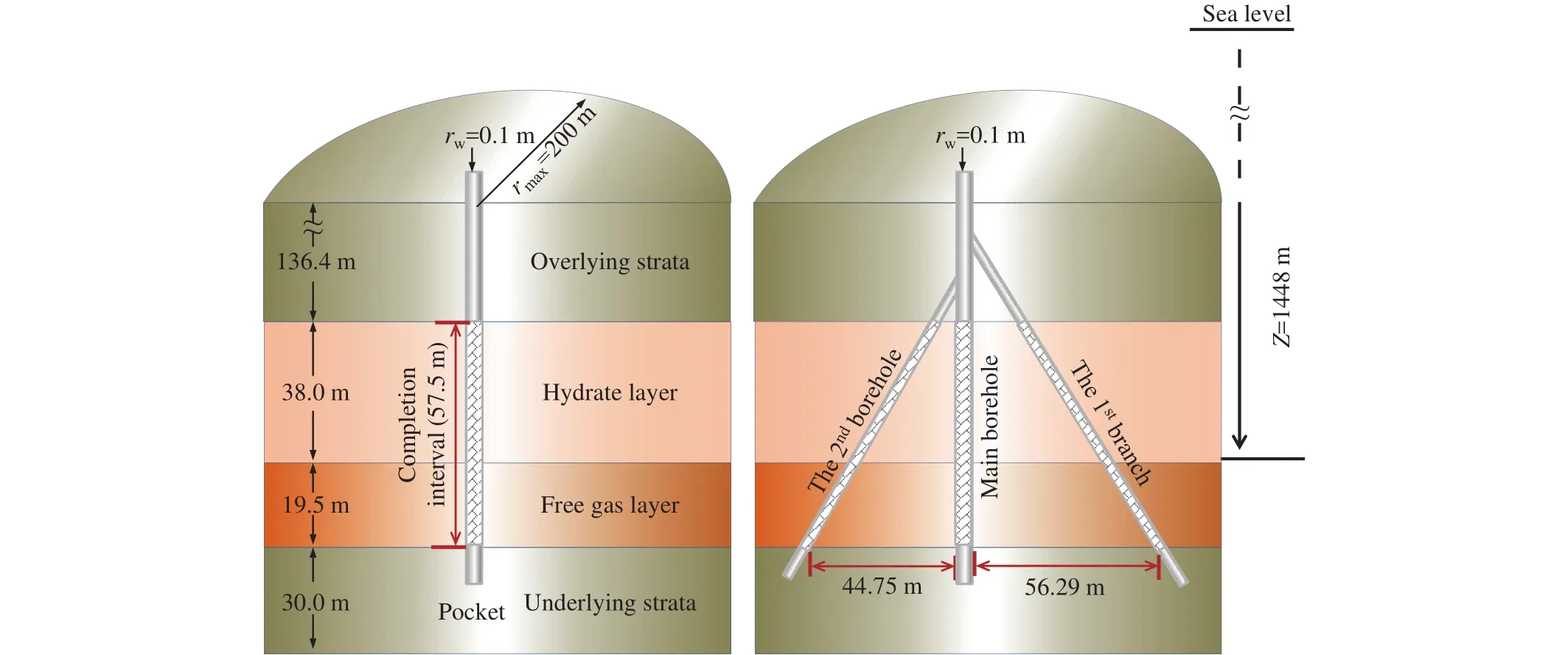
Fig.3.Schematic diagram of well profile model at site W19.
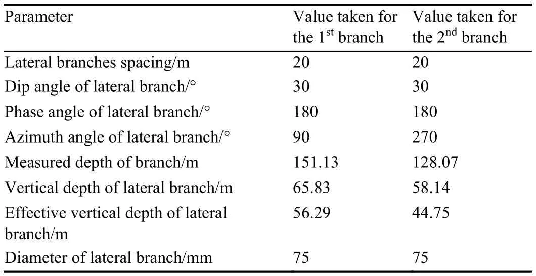
Table 1.Control parameters for well profile showed in Fig.3.
Based on the above geological data and well profile parameters, a geological model for productivity simulation based on the Tough+Hydrate was established (Moridis G J et al., 2014) and meshed.The meshing and model initialization results are shown in Fig.4.Owing to the symmetric characteristics of the model, the borehole-controlled boundaries is set as 240 m × 120 m, and two lateral branches are distributed along theXdirection of the boreholecontrolled area.In the process of simulation, both the upper and lower boundaries of the model are set to be constanttemperature and constant-pressure boundaries, and the surrounding boundaries of the model are set to be a diabatic boundaries without seepage flow (Moridis GJ et al., 2006,2011).By referencing the down-hole pressure drop control schemes used in the Nankai trough, Japan in 2013(Yamamoto K, 2015), gas and water production under the condition of a given bottom hole flow pressure (4.5 MPa) is carried out.Simulation results are compared with those obtained from a vertical well, as shown in Fig.5.
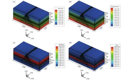
Fig.4.Meshing and initialization results of model for well profile of “well with two branches”.
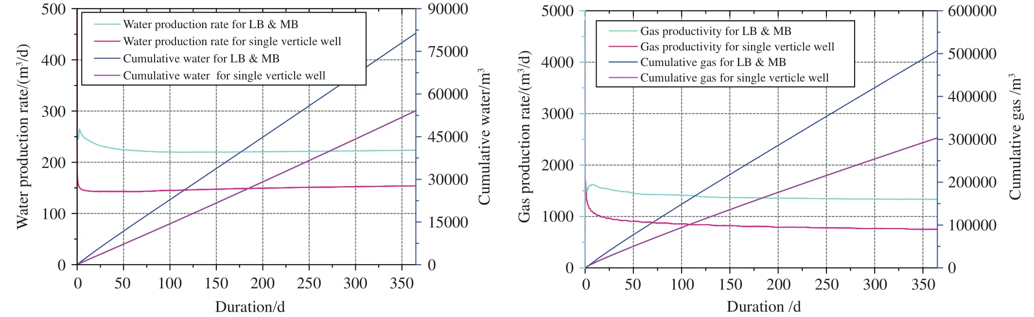
Fig.5.Simulation results of stimulation effect of well profile of “well with two branches” (one year).
From the perspective of increasing productivity, the LB &MB influences the productivity mainly through the following two mechanisms: (1) Increase the hydrate decomposition contact area, to speed up the hydrate decomposition; (2) reduce the pressure drop gradient in the reservoir around the borehole, to raise the pressure transmission efficiency in the reservoir.At the early stage of hydrate exploitation, the above two stimulation mechanisms take effect simultaneously.After the hydrate decomposition area exceeds the range covered by the multi-lateral branches, the latter mechanism gradually dominates the gas production behavoirs.The daily gas production/water production based on LB & MB and that based on conventional horizontal well/vertical well are defined as stimulation ratio and water-increase-ratio,respectively.The evolution behaviors of both stimulation ratio and water-increase-ratio are shown in Fig.6.As can be discerned from the Fig.6, the stimulation effect of LB & MB increases at the early stage of exploitation.The stimulation ratio gradually becomes constant with time, and the maximum stimulation ratio is 1.78.The water-increase-ratio decreases graduall and remains constant finally.
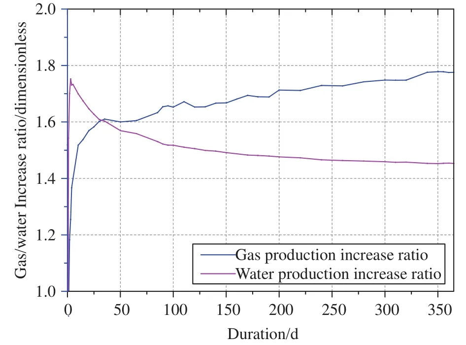
Fig.6.Changes in productivity increase ratio and water increase ratio with time.
Main cause for the increase in stimulation ratio and the decrease in water-increase-ratio may be that the exploitation based on LB & MB changes fluid flow behaviour in the formation, resulting in the change in gas-water two-phase flow resistance.It can be preliminarily concluded from the results in Fig.6 that the exploitation of Class I hydrate reservoir based on LB & MB is favorable for alleviating the water output from the reservoir.The ongoing simulations mainly are targeting to the stimulation effect and water control effect for LB & MB.
4.Geotechnical risk assessment
In addition to the strength decrease caused by hydrate decomposition, the existence of the multi-lateral branches causes the changes in stress state around the main borehole and around the multi-lateral branches, compared with that around a single vertical well (Moridis GJ et al., 2013).Therefore, we anticipate that the geotechnical risks faced by Type B profile may be higher than that faced by Type A profile.Hence the formation stability analysis based on Type A profile is shown below.
The model in Fig.7 is established based on the basic geological characteristics at site W19, and mechanical stability analysis is conducted using an self-developed THMC coupled numerical simulator (Wan YZ et al., 2018).The parameters of the multi-lateral branches are shown in Table 2.

Fig.7.Mesh diagram of model for analysis of reservoir stability in exploitation based on LB & MB.

Table 2.Control parameters for well profile of “well with eight branches”.
In Fig.7, the results obtained from the cone penetration test in the Shenhu area are used for the reservoir strength characterization, and that obtained from experimental tests in the laboratory was used to estabilish the constitutive model of hydrate-bearing sediment (Li YL et al., 2017b).
Fig.8a, b depict the distribution of shear stress and reservoir stability coefficient around the boreholes under the condition of a fixed bottom hole flow pressure (4.5 MPa).As can be discerned from the figures, the stress concentrated zones are mainly distributed around the multi-lateral branches, and these zones are faced with high risk of reservoir failure (Liu CL et al., 2017).The reservoir stability coefficients<1 (blue zones in Fig.8b) indicates that the reservoir has serious failure risks, 1<s<5 (green zones) indicates that the reservoir is in metastable state, ands>5 (red zones) indicates that the reservoir is in stable state.In LB & MB layouts,depressurization causes instability of the reservoir around the lateral branches, followed by severe sand production.When the lateral branches spacing is too small, the failure zones around two adjacent lateral branches overlap each other, and this may result in further reservoir failure.
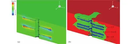
Fig.8.Mechanical response characteristics of reservoir and analysis of reservoir stability in exploitation based on multi-lateral branches.a-Distribution of shear stress around the wellbore based on multi-lateral branches; b-distribution of stability coefficient around the wellbore based on multi-lateral branches.TauYZ-Deviatoric stress in the x-y plane.
With the thickness (38 m) of the hydrate interval at site W19, different numbers/spacings of lateral branches are set respectively.The change in serious failure volume (s<1) is simulated.Fig.9 shows the change in volume ofs<1 at different numbers of lateral branches.It can be seen from the Fig.9 that, at a given thickness of reservoir, the more the lateral branches, the larger the failure zones will be encountered at the same depressurization schemes.Additionally, the more the lateral branches, the larger the hydrate decomposition range, causing enlarged failure zones.To summarize, the increase in lateral branches within an certain interval may benefit productivity, but it will causes ouvelap the failure area at the early production stages.The appropiate values of lateral branch spacings are restricted by the evolution of failure area.
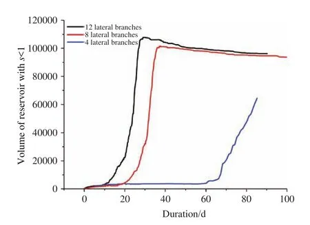
Fig.9.Change in volume of zones with reservoir failure at different numbers of lateral branches with time.
5.Discussions
The hydrate reservoir in the northern South China Sea is dominated by clayey silt, with low permeability and poor consolidation property.In view of the dual goals of raising productivity and reducing geotechnical risks, we proposed a LB & MB combined moderate sand control exploitation technique, and preliminary simulation study was conducted.The preliminary simulation results provide a support for subsequent study on design of actual field engineering parameters for the LB & MB combined moderate sand control exploitation technique.For the LB & MB combined moderate sand control exploitation technique itself, the following key aspects still remains to be furtherly studied and demonstrated.
(i) Theoretically, increasing the hydrate decomposition contact area is the main stimulation mechanisms of the exploitation technique based on LB & MB.The preliminary simulation results of typical Type A profile of indicate that the exploitation based on multi-lateral branches can not only effectively realize stimulation effect but also greatly reduce the water production ratio.At present, large quantities of numerical simulation efforts are still needed, to quantify the stimulation effects and influential factors under different well profile in different reservoirs.In particular, hydrate saturation in the clayey silt reservoir in the South China Sea exhibits evident vertical heterogeneity.The position of the multilateral branches may have significant influence on the productivity.Simulation results based on homogeneous reservoir is not enough for field operation.
(ii) In addition to the influence on productivity,geotechnical risk is an important factor to be considered in designing of parameters of multi-lateral branches.The higher the hole density and the larger the vertical depth of lateral branch, the better the stimulation effect will be achieved.However, the formation failure mechanism will become more complex, and the non-overlapping period for failure zones at a given reservoir shortens, so the production lifespan will be influenced seriously.Therefore, there are specific constraint relationships among well profile parameters and the stimulation effect, failure critical conditions, and sand production processes.If these constraint relationships can be expressed using mathematical equations, the well profile coordination equations for the LB & MB exploitation technique can be obtained, so as to provide widely applicable theoretical basis for field operation in complex formation.
(iii) To increase the reliabilities of the numerical simulation results, we are now trying to estabilish a dedicated equipment for experimental simulation (patent applying numbers: 2018215292595; 2018110919010).Nevertheless,the size effect of laboratory simulation experiment must be understood, thus the establishment of similarity criterion is necessary to enhance the field guiding significance of the simulation experiment.Based on the numerical simulation and the experimental results, parameters-coordination equations for multi-lateral branches will be established, and well profile optimization design will be conducted for the actual hydrate reservoir in the South China Sea.
6.Conclusions
(i) The LB & MB influences the productivity mainly through the following two mechanisms: increase the hydrate decomposition contact area; decrease the pressure drop gradient and raise the pressure transmission efficiency around the borehole.Typical numerical simulation based on Type A profile shows that, within the simulation period (one year), the LB & MB method can effectively raise the gas production rate and inhibit the water production rate.
(ii) The layout of multi-lateral branches in the reservoir determines the geotechnical response characteristics during depressurization.At a given thickness of reservoir, the more the lateral branches (the smaller the lateral branches spacing),the larger the failure zones within a certain production duration.Long-term exploitation causes overlap of failure zones around the multi-lateral branches, unfavorable for lengthening the exploitation period.
(iii) Optimization of the geometric parameters of lateral branches is the key for LB & MB exploitation technique.The main purpose of the optimization is to establish constraint equations among the geometric parameters of multi-lateral branches.We are now carrying out optimization simulation of multi-types of lateral branches based on the clayey silt hydrate reservoir in the South China Sea.Detailed simulation results will be discussed in future work.
Acknowledgement
This research was supported by Project of Distinguished Experts of Taishan Scholars (ts201712079); Youth Foundation of National Natural Science Foundation of China(41606078); Open Foundation of Pilot National Laboratory for Marine Science and Technology (QNLM2016ORP0207);Marine Geological Survey Program (DD20190231).Anonymous reviewers and Dr.Hao Zi-guo and Dr.Yang Yan were grateful for their constructive suggestions on the manuscript.
杂志排行

China Geology的其它文章
- A mine drainage treatment system for AMD in remediation of metal sulfide mines
- Regional gravity survey and application in oil and gas exploration in China
- Zircon U-Pb ages of the two-periods magmatism from the Xiuwacu Mo-W-Cu deposit,northwest Yunnan, China
- New zircon U-Pb ages of the Xinghuadukou Group, Xing’an block and its geological implications
- Promoting high-level cooperation in geosciences and assisting high-quality development of mining: “Belt and Road” Forum for International Geoscience Cooperation and Mining Investment was held in Xi’an, China
- Deepest deep-hole integrated geophysical observation system has successfully installed