Stability analysis of submarine slopes in the area of the test production of gas hydrate in the South China Sea
2019-01-13YohongShiQinyongLingJingpinYngQingmengYunXueminWuLingKong
Yo-hong Shi, Qin-yong Ling,b,*, Jing-pin Yng, Qing-meng Yun, Xue-min Wu,b, Ling Kong,*
a Guangzhou Marine Geological Survey, China Geological Survey, Guangzhou 510070, China
b Gas Hydrate Engineering Technology Center, China Geological Survey, Guangzhou 510070, China
c School of Science, Qingdao University of Technology, Qingdao 266033, China
Keywords:
Gas hydrate test production
Strength reduction finite element method
Submarine slope
Stability
Gas hydrate exploration engineering
South China Sea
China
A B S T R A C T
In this paper, the mechanical properties of gas hydrate-bearing sediments (GHBS) were summarized and the instability mechanism of submarine hydrate-bearing slope (SHBS) was analyzed under the background of the test production of gas hydrate in the northern part of the South China Sea.The strength reduction finite element method (SRFEM) was introduced to the stability analysis of submarine slopes for the safety of the test production.Two schemes were designed to determine the physical and mechanical parameters of four target wells.Through the division of the hydrate dissociation region and the design of four working conditions, the range and degree of hydrate dissociation at different stages during the test production were simulated.Based on the software ABAQUS, 37 FEM models of SHBS were set up to analyze and assess the stability of the submarine slopes in the area of the test production.Necessary information such as safety factors, deformation, and displacement were obtained at different stages and under different working conditions.According to the calculation results, the submarine slope area is stable before the test production, and the safety factors almost remains the same during and after the test production.All these indicate that the test production has no obvious influence on the area of the test production and the submarine slopes in the area are stable during and after the test production.
1.Introduction
Gas hydrate-bearing sediments (GHBS) refer to the deepsea sedimentary soils that contain natural gas hydrates (NGH).Distributed in the areas such as deep-sea sediments or permafrost, NGH are cage-shaped ice crystalline compounds consisting of water and natural gas formed under certain temperature and pressure conditions (Song Y et al., 2014;Jiang MJ et al., 2010).NGH are reserved in a large amount and distributed widely.The NGH resources in the South China Sea only is up to (64.35-77.22) ×109t of oil equivalent(Liu LP et al., 2019), amounting to about half of the total resources of onshore and offshore oil and gas in China.In addition, NGH enjoy the advantages such as high energy density, high convert efficiency, and cleanness, and are considered to be strategic alternative energy source with every prospect for commercial development (Liu LP et al., 2019).Therefore, the United States, Japan, India, and other countries have conducted NGH research in recent years.However, a slight increase in temperature or pressure caused by human engineering activities such as test production tends to result in hydrate dissociation owing to the extremely strict conditions of NGH for high-pressure and low-temperature.Generally,about 164 m3of methane gas at standard conditions and 0.8 m3of water can be released from 1 m3of NGH.
The hydrate dissociation tends to result in a great decrease in cementation and increase in porosity and thus GHBS become under-consolidated soil or loose sand accordingly.Then the pore pressure rises rapidly subject to the dissociated natural gas, and the effective stress consequently decreases,leading to the static liquefaction of GHBS and submarine landslide (Sultan N et al., 2004a; Liu YJ et al., 2010; He J et al., 2018).Landslide is one of the marine geological disasters with great harm.It not only presents a serious threat to the safe exploitation of NGH, but also destroys hydrate deposits,resulting in the leakage of a large amount of methane gas, the destruction of the seabed ecological environment, and the greenhouse effect (Maslin M et al., 2010).
In China, the study on gas hydrate started in the late 1980s.In October 1999, Guangzhou Marine Geological Survey, China Geological Survey took the lead in NGH survey in the northern slope of the South China Sea and collected gas hydrate samples from the Shenhu area in the northern part of the South China Sea in May 2007.In 2011,China Geological Survey started the technical preparation and experimental simulation for the test production of NGH in the sea area.In 2016, the Shenhu area in the northern part of the South China Sea was selected as the drilling location of target wells; the pre-production engineering geological survey,ocean current monitoring, the investigation and assessment of environmental effects, etc.were carried out; then the implementation scheme of test production of NGH was established (Yang SX et al., 2017; Wang LF et al., 2017).The first well of the test production of seawater gas hydrate in China was drilled in the Shenhu area of the South China Sea(also referred to as the Area) on March 28, 2017 and it ignited at 14:52 pm on May 10 successfully (Li JF et al., 2018).Natural gas was extracted from the NGH deposits that are 203-277 m below the seabed with a water depth of 1266 m.Up to July 9, the production of gas continued for 60 days, and the cumulative gas production exceeded 309000 m3.Safe and controllable mining of muddy sand-type NGH, which accounts for more than 90% of the NGH resources in the World and is the most difficult to develop (Liu LP et al.,2019), was realized firstly through this test production.This broke the situation that China follows others in the field of energy exploration and development.Independent innovation of theory, technology, engineering, and equipment was obtained during the test production and the historic leap of China from following to leading position in this field was realized.
In order to ensure the safe test production of NGH, one of the key tasks is to analyze the stability of the seabed slopes in the area.The mechanical properties of the GHBS, the factors involving in the test production of NGH, were summarized and the instability mechanism of the SHBS was analyzed after the determination of the drilling location of target well.Based on the strength reduction finite element method (SRFEM), the simulation calculation frame of the submarine slopes of the wells for test production was designed, and the FEM models of submarine slope were established.SRFEM was used to assess and analyze the stability of SHBS before, during, and after the test production.The conclusions can provide important references for the simulation of test production of NGH.
2.Mechanical properties and instability mechanism of SHBS
2.1.Mechanical properties of GHBS
It is difficult and expensive to keep the cores of GHBS in situ by pressure maintenance.Therefore, current researches mainly focus on the artificial preparation of GHBS samples(Li XP and He SM, 2012; Shi YH et al., 2015; Sultan N et al.,2004a, 2004b).Depending on the differences in sampling methods, test methods, and control variables, the research results on the mechanical properties of GHBS are different.Therefore, it is difficult to reach a consensus quantitatively(Hyodo M et al., 2013).In terms of qualitative expression, a general consensus on the mechanical properties of GHBS has been reached at present based on the synthesis of the research results obtained at home and abroad (Hyodo M et al., 2005,2013; Winters WJ et al., 2004, 2007; Wu NY et al., 2018):
(i) The elastic modulus of GHBS increases with increase in hydrate saturation, while the Poisson ratio changes very slightly.
(ii) The strength of GHBS increases with increase in hydrate saturation and the hydrate mainly contributes to the increase of the cohesion.Meanwhile, the internal friction angle nearly remains the same in spite of the change of hydrate saturation.
(iii) GHBS features strain softening and dilatancy, which become more significant with increase in hydrate saturation.
(iv) The strength and elastic modulus of GHBS increase with increase in confining pressure.
These achievements lay a solid foundation for the further study on the mechanical properties of GHBS and provide the experimental basis for the exploration of the influence exerted by test production on the stability of submarine slopes.
2.2.Instability mechanism of SHBS
Extensive researches on SHBS show that hydrate dissociation is a direct or at least an important cause of submarine landslides.Sultan N et al.(2004a, 2004b) analyzed six submarine landslides taking place in Continental Europe,and hold that the Storrega landslide which dated from more than 8000 years ago was caused by large-scale hydrate dissociation.Grozic JLH (2007) found that the dissociation of hydrates would lead to a decrease in the strength and an increase in pore pressure of the soil bearing gas hydrates, thus directly resulting in the instability of the SHBS with a water depth of less than 700 m.Kwon TH and Cho GC (2012)concluded that the increase of seabed water temperature would lead to hydrate dissociation and this would produce an excess of pore pressure according to the finite difference analysis of one-dimensional heat-flow-force coupling.Fang C and Zhang WD (2010) pointed out that the understanding of the nature of submarine landslides was far less than that of land landslides and there were still a series of basic problems to be solved.Liu F et al.(2010) analyzed the causes of the instability of Baiyun submarine landslide in the northern slope of the South China Sea and discussed the variation in pore pressure of sediment layer caused by hydrate dissociation.Zhang XH et al.(2012) carried out centrifuge experiments on synthetic hydrate sediments in laboratory in order to simulate the effect of hydrate dissociation on the stability of SHBS.The evolution process and failure characteristics of the deformation and collapse of submarine slopes caused by hydrate dissociation were studied.The basic phenomena and preliminary explanations of the influence of hydrate dissociation on the stability of SHBS were obtained.Kong L et al.(2018) analyzed the stability of SHBS under the background of the test production of NGH in the Area by adopting the orthogonal test design method, SRFEM, and multi-factor sensitivity analysis.
According to the research results obtained at home and abroad, the trigger mechanism of SHBS landslides caused by hydrate dissociation is mainly reflected in two aspects.On one hand, the hydrate dissociation reduces the compactness of GHBS and the cementation strength of particles of the sediments.On the other hand, the water and natural gas released during hydrate dissociation lead to the rapid expansion of pore volume.In the case of undrained condition or low permeability, the increase in pore pressure greatly reduces the effective stress, thus greatly attenuating the strength of GHBS.In general, many details and specific processes of the instability of SHBS are still unknown, the mechanism and process of the instability of SHBS have not been properly explained, and there are still many difficult problems to be resolved by multidisciplinary joint research.
3.Stability assessment of the submarine slopes in the area
The stability of SHBS is affected by many factors, most of which are random, fuzzy, variable and so on, and the coupling among these factors is complicated (Jiang MJ et al., 2010;Sultan N et al., 2004a, 2004b; Grozic JLH, 2007; Kong L et al., 2018).Thus it is difficult to make correct and reasonable analysis.At present, there are two kinds of methods for the study of the stability of submarine slopes: qualitative analysis and quantitative analysis.The qualitative analysis methods,such as natural historical analysis method and engineering analogy method, are widely used to determine the specific values of each parameter and tend to vary from person to person.The quantitative analysis method avoids the shortcoming of the qualitative analysis methods at a certain extent, in which limit equilibrium analysis and numerical analysis are generally adopted.The limit equilibrium method is based on the Mohr-Coulomb strength criterion.By this method, the overall safety factor of the landslide body can be obtained, while there are limitations in the application of this method.In detail, the position and form of the sliding surface as well as the influence of the shear strength characteristics on the sliding surface cannot be measured.Especially, the influence of many factors including pore water pressure, slope deformation, dynamic response, and complex terrain cannot be determined, and the instability process of landslides cannot be simulated.The numerical analysis method is mainly a finite element numerical analysis method featuring strong adaptability to complex slope.By this method, the complex constitutive relation of the soil can be analyzed and the whole process of landslide from deformation to failure can be simulated.However, it is impossible to determine the important reference index, i.e.the safety factor of slope stability, in engineering practice by this method (Zhao SY et al., 2002; Kong L et al., 2018).
SRFEM proposed in recent years has been used for the stability analysis of submarine slopes.It enjoys the advantages of both classical limit analysis method and numerical analysis method.The safety factor of slope stability as well as the information of stress, strain, displacement, and the process of slope instability can be obtained by this method(Zhao SY et al., 2002; Liang QG and Li DW, 2008).The basic principle of the SRFEM is to continuously reduce the shear strength parameters of the slopes until the ultimate failure state is reached in the established elastoplastic finite element model of the submarine slopes.The sliding failure surface is automatically obtained according to the elastoplastic finite element calculation results, and the strength reserve safety factor of the slopes can be obtained at the same time (Zhao SY et al., 2002).The reduction coefficient used in the SRFEM is equal to the safety factor of the slope numerically.SRFEM has been greatly developed in recent years owing to its simple principle and clear physical meaning.It have been verified that SRFEM is applicable to and feasible in land slopes, foundation pits, tunnels, etc.In this paper, SRFEM was used to analyze and assess the stability of SHBS in the area.
3.1.Position and basic parameters of the test production area
In early 2016, the orebodies with the numbers of W18-19 and W11-17 in Shenhu area were selected as the area for test production by the headquarters of test production.The wells in the stations of SH-W18, SH-W19, SH-W11, and SH-W17 are respectively numbered SHSC-1, SHSC-2, SHSC-3,SHSC-4 as the target wells.The locations of these wells are shown in Fig.1, the basic parameters of the hydrate reservoir in these wells are shown in Table 1, and the seismic reflection maps of the profiles of the wells are shown in Fig.2.The models were established to carry out relevant calculation based on the seismic reflection maps and parameters mentioned above.

Fig.1.Locations of the test production wells.

Table 1.Hydrate reservoir parameters.
3.2.Calculation schemes
The physical and mechanical parameters of each soil layer of SHBS are very important to the reliability of slope stability calculation.Two schemes, i.e.Scheme 1 and Scheme 2, were designed to determine these parameters of each soil layer of the submarine slopes in order to conduct comparison and analysis.Scheme 1 is the simplified geometric model with the parameters determined in relevant literature.In this scheme,the soil of the slopes was simply divided into the overlying soil, hydrate layer, surrounding soil, and underlying soil according to the seismic profiles of the four wells, and the physical and mechanical properties of each soil layer were comprehensively determined as shown in Table 2.Scheme 2 is the refined geometric model with the parameters determined by tests.In this scheme, the geometric model with refined soil layers was established based on the soil layer information obtained by the China Geological Survey from the engineering geological drilling in the test production area.Meanwhile, the physical and mechanical parameters were determined by the field and laboratory tests, and the parameters of each soil layer in Well SHSC-4 are shown in Table 3.
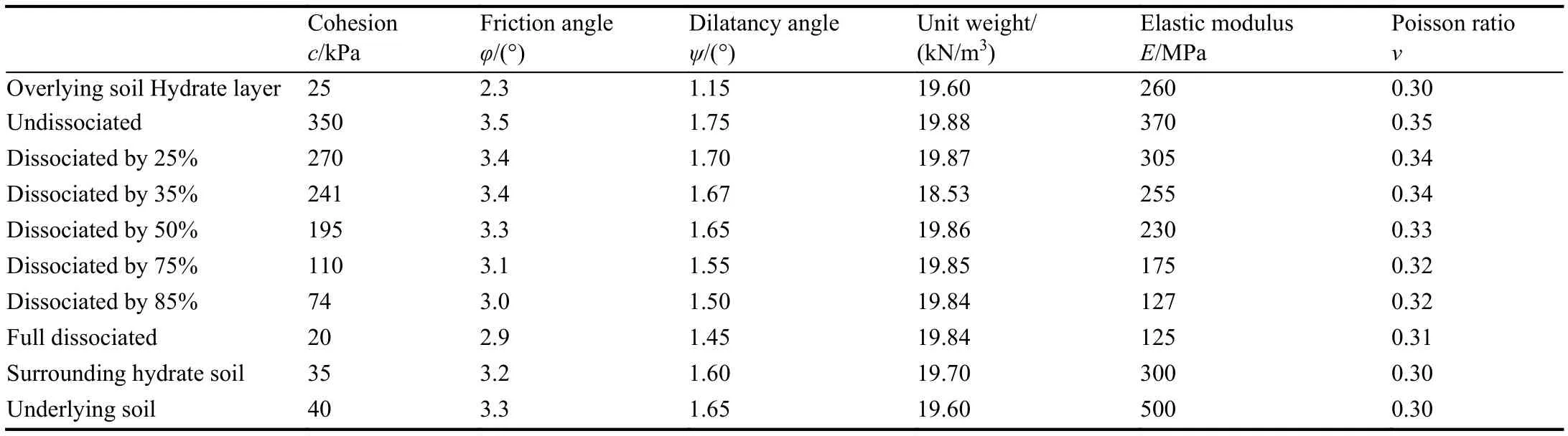
Table 2.Physical and mechanical parameters of soil (Scheme 1).

Table 3.Physical and mechanical parameters soil (Scheme 2, Well SHSC-4).
In order to provide the scientific basis for the headquarters of the test production to determine the implementation scheme, the stability analysis of the submarine slopes of the four wells was carried out before and during the test production.Since the test production was carried out in Well SHSC-4 in 2017, the stability analysis after test production was also carried out for this well.How to simulate the process of test production is the key link in the stability analysis of test production.
The test production was achieved through depressurization.After the well for test production reached the target horizon, i.e.the hydrate layer, the hydrate gradually began to dissociate with the decrease in pressure, and the dissociation zone formed in the hydrate layer.The range of the dissociation zone gradually expanded by time.However,the dissociation range of a well is limited.According to the research results of Kurihara M et al.(2009), the maximum range of the dissociation zone of a well is the central part of the well with a radius of 120 m.The degree of hydrate dissociation in the dissociation zone is also different.It is in inverse relation to the distance from the center of the well.In order to simulate the dissociation range and extent of the hydrate layer at different stages, the dissociation region was divided into four areas: A, B, C, and D (Fig.3), with the radius of each area of 30 m.In additional, four working conditions were designed correspondingly (Table 4).The first condition was used to simulate the beginning stage of mining,in which only the gas hydrates of Area A were dissociated by 25%.The second condition was used to simulate the middle stage of the mining.Under this condition, the area of hydrate dissociation was enlarged, and the degree of dissociation was increased.The hydrates of Area A and B were dissociated by 50% and 25% respectively.The third condition was used to simulate the middle-late stage.Under this condition, the area of hydrate dissociation was further expanded and the degree of hydrate dissociation was further increased.The hydrates of Area A, B, and C were dissociated by 75%, 50%, and 25% respectively.The fourth condition was used to simulate the late stage of mining, in which the dissociation range and degree of hydrate dissociation reached the maximum.The hydrates of Area A, B, C, and D were dissociated by 100%,75%, 50%, and 25% respectively.

Fig.3.Division of drilling influence areas.

Table 4.Degree of hydrate dissociation corresponding to each working condition.
After the Well SHSC-4 for test production was sealed, the hydrate in the areas of hydrate dissociation underwent a process of rebalance.After the test production, Area A and B were combined into one area, and the hydrates of the area were dissociated by 85%.Meanwhile, Area C and D were combined into one area, and the hydrates of the area were dissociated by 35% (Table 4).
3.3.Calculation model
The calculation model was set up by using the FEM software ABAQUS.The boundary constraint conditions include the fixed horizontal displacement on the left side and the right side of the model and complete fix on the bottom.The well for test production is located in the middle of the model.The pressure of the overlying seawater is simplified as the uniform load applied to upper boundary of the model.In this manner, 37 FEM models were established (Table 5).The basic steps of SRFEM were used to analyze the stability of the corresponding submarine slope.Owing to space constraints,only the FEM models and grid diagrams of Well SHSC-4 obtained by Scheme 1 and Scheme 2 are provided in this paper, as shown in Fig.4 and Fig.5 respectively.The parameters used are shown in Table 1 and Table 2.
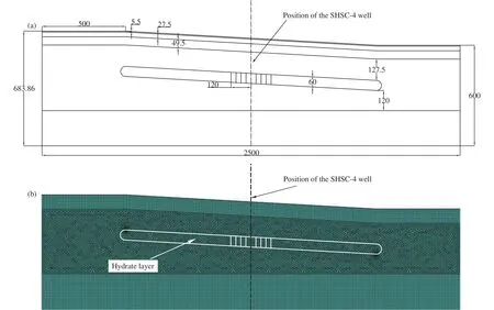
Fig.4.FEM model and FEM mesh of Well SHSC-4 (Scheme 1).a-FEM model; b-FEM mesh.

Fig.5.FEM model and FEM mesh of Well SHSC-4 (Scheme 2).a-FEM model; b-FEM mesh.
3.4.Analysis and assessment of stability
With ABAQUS as the calculation platform, analysis and calculation were conducted with SRFEM by substituting the parameters in Table 1 and Table 2 into the established FEM models.During the reduction process, the distribution state of the plastic zone and displacement of characteristic point in the models varied with the reduction coefficient.The development and penetration process of the plastic zone is explained hereafter by taking the example of the stability analysis of the Well SHSC-4 calculated by Scheme 1.
The contours of the plastic zone of the slope of Well SHSC-4 during the test production under different reduction coefficients calculated by Scheme 1 are shown in Fig.6.It can be seen that the plastic zone develops gradually with increase in reduction coefficientFruntil the zone is connected.At the beginning (Fr=1.0), the plastic strain is slightly larger in the border area of hydrate reservoir, the wellbore, and the surrounding soil than that of the other area,but the value is small and is present in a “V” shape.The position and range of the plastic strain are basically unchanged untilFris increased to 3.406.WhenFris increased to 4.754, the strain below the hydrate layer increases, and an arc plastic zone is formed at the top of the slope.Finally the plastic zone penetrates from the top to the bottom of the slope whenFr=4.769.By taking the transfixion of plastic zone as the instability criterion, it can be indicated that the slope has reached the critical failure state whenFr=4.769 and the safety factorFs=4.769.The relationship between the reduction coefficient and the displacement of characteristic point is shown in Fig.7.It can be seen from the figure that the displacement increases abruptly when the reduction factorFr=4.800.By taking the sudden change of the displacement as the criterion of slope instability, it can be indicated that the slope has reached the critical failure state whenFr=4.800, and the safety factorFs=4.800.The contour of displacement whenFr=4.800 is shown in Fig.8.It can be seen by combining Fig.6,Fig.7, and Fig.8 that the strain and the displacement will increase abruptly once the plastic zone penetrates.Further analysis shows that the plastic zone starts from the top of the slope and gradually expands below the hydrate reservoir as the advancement of reduction process.As the plastic zone expands, it is penetrated under a certain reduction coefficient.Once the plastic zone is penetrated, an extremely small increase in the reduction coefficient will cause a sharp increase in the plastic strain, resulting in a sudden change of displacement.As a result, the top of the slope sinks and the bottom of the slope rises and thus a curved slip surface forms.

Fig.6.Contours of the plastic zone under different reduction coefficients (Well SHSC-4, during test production, Condition 4, Scheme 1).a-Plastic zone when Fr=1.0; b-plastic zone when Fr=3.406; c-plastic zone when Fr=4.754; d-plastic zone when Fr=4.769.

Fig.7.Relationship between reduction coefficient Fr and displacement of characteristic point (Condition 1, Scheme 1).

Fig.8.Contour of displacement (Fr=4.800, Well SHSC-4, Scheme 1).
The calculation results of 37 groups are summarized as shown in Table 5.The safety factors greater than 8 in the table mean that the displacement mutation still does not occur when the reduction coefficient reaches 8.0, indicating that the submarine slope is absolutely stable when the safety factorFs>8.Further reduction calculation will only multiply the calculation time and is meaningless from an engineering point of view, and therefore the calculation is stopped.

Table 5.Calculation results of submarine slope stability by two schemes.
It can be seen from Table 5 that the safety factors of the submarine slopes of the stations of the wells SHSC-1, SHSC-2, SHSC-3, and SHSC-4 before test production calculated according to Scheme 1 are all greater than 1, with the smallest value reaching 3.21 in SHSC-1.The safety factors of the submarine slopes of the stations of wells SHSC-1 and SHSC-3 before test production calculated according to Scheme 2 are much greater than 1.All these indicate that the submarine slopes before the test production are stable.The stability degree of submarine slopes along the profiles of the four wells before the test production is SHSC-2>SHSC-4>SHSC-3>SHSC-1, and this is determined by the slope of seabed, and the depth and thickness of the hydrate.The safety factors before the test production calculated by Scheme 2 are greater than those calculated by Scheme 1.The main reason is that the strength parameters of the overlying soil and hydrate layer in Scheme 2 are greater than those in Scheme 1, especially the internal friction angle which is one order of magnitude greater.The higher the shear strength of soil is, the greater the safety factor is.
As for the calculation of the 28 groups during the test production, the calculation results show that the safety factors of the seabed of the four stations of the wells are greater than 1 under the four working conditions, and they are almost the same with the safety factors before the test production with insignificant change.It is indicated that the test production has no significant impact on the stability of the seabed in the test production area, and the submarine slopes in the area is stable during the test production.
For the submarine slope of Well SHSC-4, which was sealed after test production was conducted successively in May 2017, the safety factors after the test production obtained by the two calculation schemes are all greater than 1, and are slightly higher than those during the test production.It can be shown that the submarine slopes of the test production area are stable after the test production.
According to the observation results of the settlement of the drilling wellheads obtained during the test production in 2017, there is no subsidence throughout the drilling, test production, and after the test production, and the seabed in the test production area is stable.This is consistent with the results calculated by Scheme 1 and Scheme 2.
4.Conclusions
(i) SRFEM was applied to the stability analysis of SHBS based on the summary of the mechanics properties of the soil containing GHBS.The softening strength parameters were used to simulate the various working conditions during the test production.Dynamic dissociation process of hydrate reservoir was simulated under quasi-static state, and two simulation calculation schemes for the submarine slopes of the four wells for test production were proposed.
(ii) The stability of the submarine slopes at the stations of the four wells for test production before the test production was calculated by using the FEM software ABAQUS and the method SRFEM.According to the results calculated by Scheme 1, the stability safety factors of the submarine slopes at the stations of the four wells are all greater than 1.The stability safety factors of the submarine slopes of the wells SHSC-1 and SHSC-3 calculated by Scheme 2 are greater than those calculated by Scheme 1.It can be shown that the submarine slopes in the test production area are stable before test production.
(iii) Regional-scale FEM models of the submarine slopes of the four wells for test production were established through the division of hydrate dissociation region and the design of four working conditions.The calculation results of 28 groups show that the safety factors under each working condition are all greater than 1, and are almost the same with those before test production.It is indicated that the test production has no significant impact on the stability of the seabed in the test production area and the submarine slopes in the area during the test production are stable.
(iv) The stability analysis after the test production was conducted for the submarine slope of Well SHSC-4, which was sealed after the test production was successfully carried out.The safety factors obtained are all greater than 1 and slightly higher than those during test production.It can be shown that the submarine slopes in the test production area are stable after test production.
Acknowledgement
This work is funded by National Key R&D Project(2017YFC0307605), the China Geological Survey(DD20160217, DD20190218) and the National Natural Science Foundation of China (11572165), and we would like to extend our sincere appreciation for these.
杂志排行

China Geology的其它文章
- A mine drainage treatment system for AMD in remediation of metal sulfide mines
- Regional gravity survey and application in oil and gas exploration in China
- Zircon U-Pb ages of the two-periods magmatism from the Xiuwacu Mo-W-Cu deposit,northwest Yunnan, China
- New zircon U-Pb ages of the Xinghuadukou Group, Xing’an block and its geological implications
- Promoting high-level cooperation in geosciences and assisting high-quality development of mining: “Belt and Road” Forum for International Geoscience Cooperation and Mining Investment was held in Xi’an, China
- Deepest deep-hole integrated geophysical observation system has successfully installed