Buckling of Multi-segment Egg-shaped Pressure Hull
2019-01-09TANGWenxianZUOXinlongZHANGJianZHAOXiluZHUYongmei
TANG Wen-xian,ZUO Xin-long,ZHANG Jian,ZHAO Xi-lu,ZHU Yong-mei
(1.Jiangsu University of Science and Technology,Zhenjiang 212003,China;2.College of Mechanical Engineering,Saitama Institute of Technology,Saitama 369-0293,Japan)
Abstract:This paper describes a multi-segment egg-shaped pressure hull based on the geometric properties of goose eggs.Segments are connected with rib rings and made in the form of egg-shaped configuration.They have the same major axis,minor axis,eccentricity,and thickness.Results of numerical and analytical study into the strength and buckling behaviors of the multi-segment eggshaped pressure hull under external pressure are discussed.An egg-shaped pressure hull fabricated in a single piece is compared.Collapsed tests of two nominally identical egg-shaped shells in laboratory scale are shown to verify the numerical approach used to study the post-buckling of pressure hulls.
Key words:buckling;multi-segment pressure hull;egg-shaped configuration;external pressure
0 Introduction
Multi-segment pressure hulls have attracted considerable attention in recent years because of the requirements for deep sea exploration and utilizing modular pressure hulls.The segment pressure hull is a closed thin-walled structure that is subjected to uniform external pressure and composed of several joined segments with similar configuration,such as a shell of revolution with positive Gaussian curvature.It has numerous possible applications in underwater equipment,like deep manned submersibles and unmanned submersibles(Liang,2004)[1].However,multi-segment pressure hulls usually fail due to a lack of stability,which is greatly influenced by the shapes of the segments and the rib rings connecting them(Blachunt and Smith,2008)[2].
Spherical shells are widely used as constituents of multi-segment pressure hulls because they efficiently distribute stress and strain in the material.Extensive research has been published regarding the design and buckling analysis of multi-segment pressure hulls.Garland(1968)[3]designed and fabricated a double-segment spherical pressure hull together with a triple-segment spherical pressure hull.Leon(1971)[4]experimentally investigated a doublesegment spherical pressure hull composed of Ti alloy and detailed the effects of the materials of the rib ring on the collapse load.Hall et al(1991)[5]proposed a double-segment spherical pressure hull composed of graphite/epoxy composites,with a rib ring made of Ti alloy.This led to a 46%decrease in the weight of the pressure hull below the weight of a steel hull.More recently,a series of investigations have investigated the structural optimization of multi-segment spherical pressure hulls(Liang,2004[1];Lu,2004[6]).However,spherical shells are highly imperfection-sensitive;any small change causing geometric imperfections may result in a substantial decrease in the buckling load(Pan and Cui,2010[7];2011[8]).Furthermore,housing humans and equipment in a spherical shape can be challenging.Therefore,it is necessary to seek a non-typical axisymmetric shell with positive Gaussian curvature to replace the spherical shell.
A method for solving this problem is to incorporate barreled shells,which are cylindrical shells with positive meridional curvature.They combine the advantages of cylindrical and spherical shells.For example,Magnucki and Jasion(2013)[9]demonstrated that a barreled pressure hull may serve as an alternative for cylindrical and spherical pressure hulls.They proposed a family of barreled shells,namely shells of revolution with constant meridional curvature(Jasion,2009)[10],Cassini oval curvature(Jasion and Magnucki,2015a)[11],and clothoidal-spherical curvature(Jasion,2015b)[12].The buckling behaviors of these barreled shells were investigated analytically and numerically.The combination of numerical and analytical approaches is a necessary tool to completely characterize and describe post-buckling modes and equilibrium paths of shells.Merodio and Haughton(2010)[13]extended membrane analysis to an elastic tube of finite thickness made of an isotropic incompressible material,and have successfully solved the problem of bulging instabilities.Johannes et al(2015)[14]derived an analytical model to predict the effect of braid and tube for the multi-braided tube segments on the nonlinear response,and demonstrated the pressure-volume relation instabilities of these multibraided tube segments through experimental results and numerical simulations.Blachut et al(2001[15];2002[16];2013[17])have prompted a serials of tests to explore the buckling behavior of bowed-out shells-shells of revolution with constant meridional curvature or elliptical curvature.Numerical simulations were performed for these shells as well.Favorable agreement between the experimental results and theoretical predictions was obtained.Furthermore,they conducted numerical and experimental investigations on the buckling behavior of multi-segment bowed-out pressure hulls(Blachunt and Smith,2008)[2].The shape of each segment was a shell of revolution with constant meridional curvature.The effect of the rib ring thickness on the buckling load was also studied.The predicted collapse loads of the multi-segment pressure hulls agreed well with the experimental results.
Another favorable set of shapes is the set of egg-shaped shells with multifocal surfaces of positive Gaussian curvature(Babich,1993)[18],in the view that eggshells offer such advantages as excellent load capacity,weight-to-strength ratio,span-to-thickness ratio,and aesthetics.Bionics has been employed to propose egg-shaped pressure hulls based on the geomet-ric properties of goose eggshells(Zhang,2015[19];2016[20]),which could optimally coordinate the safety,capacity,and man-machine-environment characteristics of deep submersibles.These previous findings motivated us to investigate a multi-segment non-typical pressure hull,the segments of which are egg-shaped shells.
Therefore,this paper presents a multi-segment egg-shaped pressure hull comprising three identical segments with an egg-shaped configuration.The material was assumed to be Ti alloy(Ti-6Al-4V).The major axis,minor axis,eccentricity,and thickness of the segments were 2 453 mm,1 693 mm,54.5 mm,and 15 mm,respectively.All segments were arranged symmetrically.The pre-buckling state,buckling state,and post-buckling state of the proposed hull are presented numerically and analytically.For comparison,an equivalent egg-shaped pressure hull with a single piece is also provided and analyzed.Collapsed tests of two nominally identical egg-shaped shells made of 304 stainless steel in laboratory scale are carried out to verify the numerical approach.
1 Geometry of the multi-segment egg-shaped pressure hull
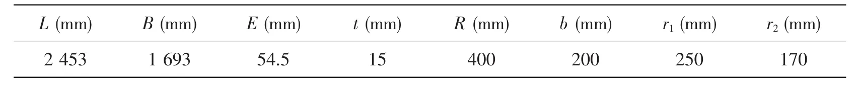
The current multi-segment pressure hull consists of three identical segments:the bow segment,middle segment,and rear segment.These segments are connected with two rib rings.As illustrated in Fig.1,the adjacent intersecting segments are arranged with reflective symmetry;the sharp end of the bow segment is connected with the sharp end of the middle segment,and the blunt end of the middle segment is connected with the blunt end of the rear segment.Each segment is egg-shaped,the curvature of which is expressed by Eq.(1)in Cartesian coordinates;this is a modified version of the Kitching function(Kitching,1997)[21],as shown in Fig.2.This function has been frequently used to describe the contours of eggshells.

Fig.1 Geometry of the multi-segment egg-shaped pressure hull

where L is the major axis,B is the minor axis,and e is the eccentricity.
According to Eq.(1),three parameters,the major axis(L),minor axis(B),and eccentricity(e)control the geometry of the egg-shaped shell.The relationships between these parameters were obtained from tests on 50 Zhejiang white goose eggs(taken from geese that were approximately 2 years old).In the tests,major axis,minor axis,and eccentricity of all eggs were measured using an optical 3D scanner.According to the experimental results,the average value of B/L was 0.69 and the average value of L/e was 45.Moreover,the meridians of these eggs were also obtained from the tests and compared with Eq.(1).The mean Pearson’s correlation coefficient between them was approximately 0.998.

Fig.2 Meridian of the egg-shaped pressure hull
For each segment,the minor axis,the thickness(t),opening radius were assumed to be 1 693 mm,15 mm,and 400 mm,respectively.Then,the size and shape of each segment were determined in combination with B/L and L/e.The outer radius(R)of all the rib rings was set to be equal to the opening radius.Their width(b)was assumed to be 200 mm.Their inner radii were obtained on the basis of the principle of equal displacement in the direction of the minor axis,detailed in Section 3.The material of each segment and rib ring was assumed to be Ti alloy(Ti-6Al-4V),which has been extensively applied in the pressure hulls of deep submersibles such as the Chinese deep manned submersible Jiaolong.
The equivalent egg-shaped pressure hull with a single piece(which can be termed‘the egg-shaped pressure hull’for short),is shown in Fig.2.It can be compared with the multisegment egg-shaped pressure hull.Its size,shape,and material are assumed to be identical to those for each segment of the multi-segment egg-shaped pressure hull,but unlike the multisegment hull,the egg-shaped pressure hull has no openings.
2 Design of rib rings
A previous study suggested that the rib rings of multi-segment pressure hulls have considerable influence on the stress and buckling behaviors of such pressure hulls.Blachut and Smith(2008)[2]reported that the collapse load of a two-segment bowed-out pressure hull initially increases with the flange thickness;this continues up to a constant value,beyond which no further increase can be achieved.Furthermore,Gou and Cui(2009)[22]proposed an optimal multi-segment spherical pressure hull on the basis of the principle of equal displacement in the direction of the minor axis:at intersections between the rib rings and segments,radial deformation of each segment would be consistent with that of a corresponding single spherical pressure hull without openings at the same point(in the case of identical loading).
In this study,the size of rib rings for the multi-segment egg-shaped pressure hull was determined in line with Gou and Cui(2009)[22].First,the pre-buckling state of the egg-shaped pressure hull was determined in order to obtain the displacement of the egg-shaped segment without openings along its minor axis.Second,the displacement of the intersecting point for each segment was derived along the minor axis,and the inner radius of each rib ring was determined.
2.1 Analytical pre-buckling state of the egg-shaped pressure hull
The egg-shaped pressure hull is a shell of revolution subjected to uniform external pressure.According to thin shell theory,in the case of axial symmetry(Ventsel and Krauthammer,2001)[23],the geometric equations of the egg-shaped pressure hull are as follows:

where

where ε1is the circumferential strain,ε2is the meridional strain,u is the meridional displacement,w is the radial displacement,R1is the principal radius of the meridian,R2is the principal radius of the parallel circle,and θ is the angle between major axis and the radius of meridian.
The constitutive equation of the egg-shaped pressure hull is given as:

where

where N1is the meridional membrane force,N2is the circumferential membrane force,p is the external pressure,and μ and E are Poisson’s ratio and Young’s modulus of the material,respectively.
Subsequently,the radial displacement(w)of the egg-shaped pressure hull can be obtained from Eqs.(2)-(9):

Finally,the displacement(δ)of the egg-shaped pressure hull along its minor axis is de-termined as:

2.2 Inner radii of rib rings
According to the principle of equal displacement in the direction of the minor axis,the displacement of the intersecting point for each segment along the minor axis is identical to that of the corresponding rib ring.

Fig.3 Loading of the multi-segment egg-shaped pressure hull
Fig.3 shows the loading conditions of the multi-segment egg-shaped pressure hull.Through the application of linear elastic mechanics,the radial displacement of the left rib ring(δr1)and the right rib ring(δr2)can respectively be determined as follows:

where r1is the inner diameter of the left rib ring,r2is the inner diameter of the right rib ring,and pr1and pr2are respectively the radial pressure imposed on the left rib ring and the right rib ring,determined in the following form:

where F1,F2,F3and F4are meridional membrane forces applied by the segments,and α and γ are angles between the major axis and the radius of meridian(see Fig.3).
Finally,the inner radii of the rib rings were obtained on the basis of the aforementioned principle:the radial displacement of a rib ring equals that of an intersecting point for each segment,as listed in Columns 7 and 8 of Tab.1.Other geometric parameters of the multi-segment egg-shaped pressure hull are also summarized in Tab.1.
Tab.1 Geometric parameters of the multi-segment egg-shaped pressure hull
3 Numerical result and discussions
Prior work has demonstrated that the finite element method(FEM)is an effective means for determining the buckling pressure and mode of a thin-walled structure.For instance,Schmidt(2000)[24]reported that the stability of shell structures can be obtained through numerical simulation.In the present study,numerical calculations were performed with the FEM on the ABAQUS software system to determine the pre-buckling states,buckling states,and post-buckling states of the egg-shaped pressure hull and multi-segment egg-shaped pressure hull.
The midsurfaces of the two pressure hulls were modeled using fully integrated S4 shell elements to avoid hourglassing.The number of elements was established on the basis of a mesh convergence analysis,which was in line with Jasion(2015b)[12].The finite element model of the egg-shaped pressure hull was composed of 4 640 finite elements and 4 642 nodes,and the model of the multi-segment egg-shaped pressure hull comprised 13 120 finite elements and 13 122 nodes.Details of these two models are given in Fig.4.In this analysis,an external pressure(p0)of 1 MPa was imposed on the whole area of each pressure hull.The material properties were obtained by several tension coupons(Li,2005)[25]and are described as follows(Beer,1991)[26]:

where n is the strain hardening parameter(59.327),E is Young’s modulus(110 GPa), μ is Poisson’s ration(0.3),and σyis the yield strength(830 MPa).
Fig.4 FE models of the egg-shaped pressure hull(a)and multi-segment egg-shaped pressure hull(b)
3.1 Pre-buckling state
To determine the stress behaviors of the two hulls,a static analysis was conducted using ABAQUS/Standard.Fig.5 shows the von Mises equivalent stresses obtained from the static analysis.The stress in the middle area of the egg-shaped pressure hull is represented digitally in Fig.6,including the analytical results obtained from Eqs.(8),(9),and(17).The origin of the horizontal coordinate system was defined at the equator of the egg-shaped pressure hull,along the major axis from the sharp end to the blunt end.According to Fig.6,correlations between the numerical prediction and analytical results were highly favorable(±5.91%).

where σr4is the von Mises equivalent stress.

Fig.5 Stress nephograms of(a)the single egg-shaped pressure hull and(b)the multi-segment egg-shaped pressure hull
As shown in Fig.5,for the single eggshaped pressure hull,the stress was equally distributed around the circumferences because of its structural symmetry around the major axis.In the meridional curve,the stress first increased,and then decreased stably from the sharp end to the blunt end.These findings may have resulted from variations of the meridional radius and the circumferential radius of curvature of the single egg-shaped pressure hull along the major axis.The maximal stress obtained from the numerical calculation was at the equator of the eggshaped pressure hull(37.781 MPa),where the meridional radius and circumferential radius of curvature were maximal.In accordance with the mechanics of elasticity,dividing the yield stress of the material(830 MPa)by the maximal stress(37.781 MPa)showed that the yielding load of the egg-shaped pressure hull was 21.969 MPa.

Fig.6 Comparison of stresses for two egg-shaped pressure hulls(a:FEM solution for the bow segment;b:FEM solution for the egg-shaped pressure hull;c:analytical solution for the egg-shaped pressure hull;d:FEM solution for the middle segment;e:FEM solution for the rear segment)
The stress behavior was similar for each segment of the multi-segment egg-shaped pressure hull(see also Figs.5 and 6).The maximal stresses of the bow segment(38.032 MPa),middle segment(37.986 MPa),and rear segment(38.094 MPa)approximated the maximal stress of the egg-shaped pressure hull.From this,the yielding load of the multi-segment egg-shaped pressure hull was inferred to be 21.788 MPa.The difference between the yielding loads of the two pressure hulls was only 0.82%.In addition,stress near the rib ring of the multi-segment egg-shaped pressure hull was lower than that at the same location of the egg-shaped pressure hull,suggesting that the stress concentration caused by the edge effect could be avoided at the joints,where sudden changes of thickness and curvature exist.These findings indicate that the stress behaviors of the multi-segment egg-shaped pressure hull could be evaluated through a static analysis of the egg-shaped pressure hull.
3.2 Buckling state
In this section,linear eigenvalue buckling analysis is performed to show the buckling loads and buckling modes of the egg-shaped pressure hull,together with the loads and modes of the multi-segment egg-shaped pressure hull.To prevent rigid body motion,three random spatial nodes were respectively fixed along the x-,y-,and z-axes.These constraints do not introduce over constraint into the models because pressure is equally applied on the whole surface area.The reaction forces at these nodes are zero.Figs.7-8 and Tabs.2-3 show the results obtained from the numerical predictions.

Fig.7 Buckling modes of the single egg-shaped pressure hull:(a)First mode;(b)Second mode;(c)Third mode;and(d)Fourth mode

Tab.2 Buckling loads and circumferential wave(n)of the egg-shaped pressure hull

Fig.8 Buckling modes of the multi-segment egg-shaped pressure hull:(a)First mode;(b)Second mode;(c)Third mode;(d)Fourth mode;(e)Fifth mode and(f)Sixth mode

Tab.3 Buckling loads and circumferential wave(n)of the multi-segment egg-shaped pressure hull
As can be seen from Fig.7 and Tab.2,for the egg-shaped pressure hull,the even buckling loads were approximated the odd ones,and the even buckling modes were identical to the odd ones.The first buckling load of the egg-shaped pressure hull was 14.378 MPa.This value was in good agreement with the critical load(14.786 MPa)obtained from Eq.(18),an analytical formula developed by Mushtari.The difference between the numerical prediction and the analytical solution was barely 2.76%.A comparison of Fig.5 and Tab.2 shows that the buckling load of the egg-shaped pressure hull was even lower than its yielding load.The buckling appears to have dominated the failure of the egg-shaped pressure hull.The first buckling mode took the form of nine circumferential waves in the middle part of the pressure hull,which is the typical buckling mode for shells of revolution with positive Gaussian curvature.For example,Jasion and Magnucki(2007)[27]reported that the buckling shape of a barreled shell(R=1 278)had the form of 34 circumferential waves,and the number of waves depended on the geometry of the shell.

where pqis the elastic buckling load,is the mean value of the principal radius of the meridian for the hull section bounded by the nodal curves of the local buckling forms,andis the mean value of the principle radius of the parallel circle.Details regarding Eq.(18)have been reported by Zhang(2015)[19]and Babich(1993)[18].
The first six buckling loads and corresponding buckling modes of the multi-segment eggshaped pressure hull can be found in Tab.3 and Fig.8.According to Tab.3,the six buckling loads were highly similar.The difference between the minimum buckling load(14.386 MPa)and the maximum buckling load(14.391 MPa)was less than 0.03%.All buckling modes contained nine circumferential waves.Comparing Fig.5 and Tab.3,the buckling appears to have dominated the failure of the multi-segment egg-shaped pressure hull,which was identical to the failure of the egg-shaped pressure hull.In addition,the odd buckling loads and modes(first,third,and fifth)of the multi-segment egg-shaped pressure hull were identical to the first load and mode of the egg-shaped pressure hull.The even buckling results(second,fourth,and sixth)of the multi-segment egg-shaped pressure hull were identical with the second result of the egg-shaped pressure hull.These phenomena occurred because the meridian of each segment for the multi-segment egg-shaped pressure hull was derived from that of the eggshaped pressure hull;even if the sharp end or blunt end of these segments were replaced by the equivalent rib rings,the effects on the elastic buckling behavior would be negligible.Hence,the elastic buckling behavior of the multi-segment egg-shaped pressure hull can be determined through a linear buckling analysis of the egg-shaped pressure hull on the basis of either a numerical simulation or analytical calculation.Moreover,these results indicate that the multi-segment egg-shaped pressure hull can be highly sensitive to imperfections,and the single modes together with combinations of modes with equal weights should be considered as initial imperfection possibilities in the post-buckling analysis.
3.3 Post-buckling state
Linear buckling analysis is focused only on the elastic buckling behavior of ideal shell structures.This method often yields very conservative results without considering the effects of initial geometric imperfections and nonlinearities on the buckling of shells.The post-buckling behavior analysis of the cylinder shell with the first eigenmode as initial equivalent geometric imperfection can be found in Rodríguez and Merodio(2016)[28].
In the current study,the geometrically and materially nonlinear analysis with imperfections included(GMNIA)was conducted using the arc-length method,in accordance with ENV 1993-1-6(2007)[29].Accordingly,the realistic buckling loads of the two pressure hulls were obtained without any additional reductions(Schmidt,2000[24];Alhayani,2013[30]).
For this goal,the initial equivalent geometric imperfection of the egg-shaped pressure hull was introduced in the form of the first buckling mode.In the case of the multi-segment eggshaped pressure hull,the individual odd buckling modes(first,third,and fifth)as well as combinations of these modes were introduced.This yielded a total of seven types of initial equivalent geometric imperfections(see Fig.8).To compare the results obtained from these initial equivalent geometric imperfections,the amplitude of all imperfections was assumed to be 5 mm,which is one-third of the thickness of each pressure hull.This value met the requirement for Class A shells presented in ENV 1993-1-6(2007)[29].Furthermore,in all cases,the material was assumed to be elastic-plastic based on Eq.(16).Post-buckling behaviors of two pressure hulls are summarized in Tab.4 and Figs.9,10 and 11.

Tab.4 Critical buckling loads and post-buckling loads of the multi-segment egg-shaped pressure hull
Figs.9 and 10 provide the equilibrium paths of the two pressure hulls,plots of the applied load(pp)normalized by the initial applied pressure(p0=1 MPa)versus the maximum deflection(Δ)normalized by the thickness(t)of each pressure hull.In the case of the egg-shaped pressure hull,the post-buckling load first increased monotonically,and then sharply decreased after reaching the peak value(8.388 MPa),indicating that the equilibrium path was unstable.This is a typical property for most shells of revolution with positive Gaussian curvature(Bažant and Cedolin,2003)[31].

Fig.9 Equilibrium path of the egg-shaped pressure hull(the post-buckling load,pp,normalized by the applied pressure,p0,versus the maximum deflection,Δ,normalized by the thickness,t)
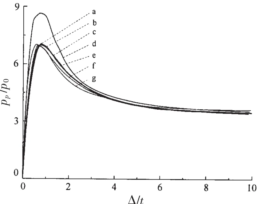
Fig.10 Equilibrium paths of the multi-segment hull with seven initial imperfections:(a)The first mode;(b)First-fifth mode;(c)Third-fifth mode;(d)Fifth mode;(e)First-third-fifth mode;(f)Third mode and(g)First-third mode
As shown in Fig.9,the critical buckling load of the egg-shaped pressure hull was 8.388 MPa.This value was nearly three-fifths of the linear eigenvalue buckling load(14.378 MPa).The egg-shaped pressure hull appeared to be less sensitive to the imperfections than the spherical pressure hull was,the experimental load of which was only one-fifth to one-third of the theoretical values(Wang,2007)[32].These findings extend those of Jasion(2015a[11];2015b[12])and Blachut(2002)[16],confirming that bowedout cylindrical shells with positive Gaussian curvature,such as the Cassini oval shell,clothoidalspherical shell,ellipsoidal shell,and the current egg-shaped shell,are moderately sensitive to the initial geometric imperfections.Comparing Figs.5 and 9 shows that the post-buckling load of the single egg-shaped pressure hull was only 38.18%of its yielding load.Buckling evidently dominated the failure of the egg-shaped pressure hull.The buckling mode at the peak of the equilibrium path for the egg-shaped pressure hull took the form of nine circumferential waves,which was in line with the linear buckling results.The post-buckling mode at the end of the equilibrium path was a single local dimple at the equator.
Previous studies have stated that initial geometric imperfections play a pivotal role in the buckling analysis of a shell structure(Saullo,2014)[33].In this study,seven initial equivalent geometric imperfections,including the first,third,fifth,first-third,first-fifth,third-fifth,and first-third-fifth buckling modes,were respectively imposed on a perfect model of the multisegment egg-shaped pressure hull.As shown in Fig.10,as with the egg-shaped pressure hull,all equilibrium paths of the multi-segment egg-shaped pressure hull were unstable,regardless of the difference in the imperfections.The peak values(critical buckling load)of these paths ranged from 7.030 to 8.672 MPa.The collapse load of the multi-segment egg-shaped pressure hull(7.030 MPa)was 87%of that of the egg-shaped pressure hull(8.388 MPa).This finding is in line with that of Btachut and Smith(2008)[2].In that study,the collapse load of the multi-barrel hull was approximately 13.90 MPa,76%of that(18.09 MPa)of the single barreled hull.Furthermore,comparing Fig.5 and Tab.4 reveals that the buckling dominated the failure of the multi-segment egg-shaped pressure hull.
According to Fig.11 and Tab.4,the first buckling mode was not the worst geometric imperfection;the critical buckling loads obtained from other imperfections(except the fifth buckling mode)were lower than those obtained from the first buckling mode,and the first-fifth buckling mode yielded the most conservative result.These results confirmed that for shells with closely spaced eigenvalues,one of the linear combinations of the clustered buckling modes may be the worst imperfection shape.Furthermore,the rear segment was prone to failure,whereas the middle segment was the safest constituent(see Tab.4).
For the multi-segment egg-shaped pressure hull with different imperfections,all buckling modes at the peak of the equilibrium paths had the form of nine circumferential waves,and all post-buckling modes at the end of the equilibrium paths were local dimples at the equator.These results resembled those of the egg-shaped pressure hull.Therefore,it may be inferred that the collapse load of the multisegment egg-shaped pressure hull can be determined by the collapse load of the eggshaped pressure hull multiplied by a rational reduction factor.
3.4 Verification of numerical approach
In order to verify the previous numerical approach used to study the post-buckling of pressure hulls,two nominally identical eggshaped shells in laboratory scale were measured for geometry,tested to collapse,and analysed numerically.The major axis(L),minor axis(B),and eccentricity(e)of egg-shaped shells were 232 mm,160 mm and 5 mm,respectively.The egg-shaped shells were designated as ES1 and ES2.Each shell was manufactured using the tungsten inert gas butt welding of a blunt dome and a sharp dome.Domes were cut and cold-pressed from 304 thin stainless steel sheets with a nominal thickness of 1.5 mm.

Fig.11 Buckling modes of the multi-segment egg-shaped pressure hull with seven initial imperfections respectively showing the critical buckling modes and postbuckling mode with the first mode imperfections(1-a and 1-b),third mode imperfections(2-a and 2-b),fifth mode imperfections(3-a and 3-b), first-third mode imperfections(4-a and 4-b),firstfifth mode imperfections(5-a and 5-b),third-fifth mode imperfections(6-a and 6-b),and first-third-fifth mode imperfections(7-a and 7-b)n:number of circumferential waves.
Firstly,the wall thickness of each shell was measured using an ultrasonic probe at 21 equidistant points along a meridian for eight equally spaced meridians,resulting in 8×19+2=154 measuring points.The scatter of the thickness around the overall average at the same latitude is illustrated in Fig.12.As we can see,the small scatter at each latitude shows a reasonably high degree of axisymmetry.Also,the wall thickness for each shell differs substantially along its meridional direction,which may result from the cold-pressing process.This relatively large variation was considered in numerical analysis.Then,the real shape of each shell was precisely measured using a three-dimensional optical scanner(Open Technologies Corporation,≤0.02 mm).In this way,the CAD models of egg-shaped shells could be obtained,including deterministic geometric manufacturing-related imperfections.These CAD models were used to elaborate the numerical models.

Fig.12 The wall thickness profile from sharp end to blunt end for two egg-shaped shells made of 304 stainless steel(the average wall thickness,tave,the maximum wall thickness,tmax,the minimum wall thickness,tmin);the horizontal coordinate corresponds to that of Fig.2

Fig.13 Views of two collapse egg-shaped shells caused by external hydrostatic pressure;both failure modes assumed the form of a local dent
After the measurements,two egg-shaped shells were tested to collapse in a pressure chamber with 200 mm inner diameter,400 mm total length,and 20 MPa maximum pressure.The chamber used water as the pressurising medium.The value of pressure inside the cylinder was recorded using a pressure transducer.Both shells failed suddenly with a sharp decrease in pressure.The collapse pressure was 7.12 MPa for the ES1 egg-shaped shell,and 6.96 MPa for the ES2 egg-shaped shell,respectively.Shortly after the testing,the collapsed shell was removed from the chamber.Fig.13 depicts the collapse modes of the test shells.Both shells failed in the mode of a local dent nearby the equator,which is identical to Fig.9.This small variation in collapse pressure and identical collapse mode shows the good repeatability of the experiment.
Finally,the nonlinear numerical analysis was carried out for the tested egg-shaped shells in line with the previous approach in Section 4.3.The finite elements of two egg-shaped shells were generated freely and uniformly on its measured geometry,which included initial deterministic geometrical imperfections(Fig.14).As a result,the ES1 egg-shaped shell consisted of 8 340 S4 shell elements and 30 S3 shell elements;the ES2 egg-shaped shell consisted of 8 399 S4 shell elements and 40 S3 shell elements.1 MPa external pressure was imposed on the surface of each shell.The material was assumed to be elastic-plastic,i.e.,the same as parent material.The parent material properties of the egg-shaped shells were obtained by testing four flat tension coupons.They were taken from the same sheets used to manufacture egg-shaped shells.The average material properties were as follows:Young’s modulus E=186.1 GPa,yield strength σyp=276.8 MPa,Poisson’s ratio μ=0.25,the strain hardening parameters n=4.216.In addition,the wall thickness of each dome was modeled as overall average wall thickness(Fig.12),which varied in the meridional direction.Fig.15 and Fig.16 present the results obtained using the nonlinear analysis.

Fig.14 FE models generated freely and uniformly on egg-shaped shells’measured geometry

Fig.15 Equilibrium paths of the tested egg-shaped shells made of 304 stainless steel
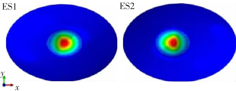
Fig.16 The post-buckling modes for both shells at the end of their equilibrium paths corresponding to Fig.15
Both shells have an unstable character and a similar post-buckling mode.For example,Fig.15 illustrates the equilibrium path of the egg-shaped shells:the vertical axis corresponds to the applied load(pp)normalized by the initial applied pressure(p0=1 MPa);the horizontal axis corresponds to the maximum deflection(Δ)divided by nominal thickness of sheet(1.5 mm).The post-buckling modes for both shells at the end of their equilibrium paths are given in Fig.16.It appears that two modes have the same form of a local dent near the equator,which is well similar to the experimental ones.Moreover,the numerical buckling load,which corresponds to the peak point of the equilibrium path,is 6.19 MPa for the ES1 egg-shaped shell,and 6.53 MPa for the ES2 egg-shaped shell,respectively.The predicted value is as many as 87%-94%of the experimental one,which suggests a good agreement.This small difference may be associated with the material hardening during the pressed process of each shell,whose yield strength could increase significantly.
4 Conclusions
In this paper,the results of numerical and analytical study into the strength and buckling behaviors of the multi-segment egg-shaped pressure hull are provided;furthermore,an eggshaped pressure hull with a single piece has been presented for comparison.
The relevant states were the pre-buckling,buckling,and post-buckling states.We found that the numerical strength and buckling behaviors of the multi-segment egg-shaped pressure hull were consistent with those of the egg-shaped pressure hull;this agreed well with analytical predictions and results obtained in previous studies,even though the collapse load of the multi-segment egg-shaped pressure hull was slightly lower than that of the egg-shaped pressure hull.
The buckling dominated the failure of the multi-segment egg-shaped pressure hull,which was moderately sensitive to initial geometric imperfections.Linear combinations of the clustered buckling modes should be imposed on the perfect model to determine the minimum collapse load of the multi-segment egg-shaped pressure hull.This can provide a framework from which future studies can predict the buckling behaviors of a multi-segment pressure hull with closely spaced eigenvalues.Most notably,to our knowledge,this is the first publication of a new type of non-typical shell configuration for a multi-segment pressure hull,from a bionic point of view.
However,some limitations should be acknowledged.Although some of the numerical predictions were confirmed analytically and comparatively,the buckling behaviors of the multisegment egg-shaped pressure hull were not verified experimentally.Hence,future studies should be devoted to experimental investigations on the buckling behaviors of multi-segment egg-shaped pressure hulls.To satisfy segment requirements and to improve the hydrodynamic properties of submersibles,the performance levels of various multi-segment egg-shaped pressure hulls with different segment sizes should be studied.
Acknowledgments
The authors thank Prof.Liu Tao for his invaluable technical support and Prof.Wu Wenwei for critically reviewing our results,and would like to express their appreciation to the anonymous reviewers whose substantial and constructive comment significantly improved the paper.
杂志排行

船舶力学的其它文章
- Dynamic Stability of Liquefied Cargo Ship in Waves
- Investigation on Time Domain Motions for Ship and Floating Structure and Coupled with Nonlinear Sloshing
- Overset Simulations of Submarine’s Emergency Surfacing Maneuvering in Calm Water and Regular Waves
- A Revised Method for Predicting Added Waves Resistance Based on Comparison of Theoretical and Empirical Results for VLCC Hull Forms
- 3D Nonlinear Hydroelastic Response and Load Prediction of A Large Bulk Carrier in Time Domain
- Strength Characteristics of Maraging Steel Spherical Pressure Hulls for Deep Manned Submersibles