Geo-location for Ground Target with Multiple Observations Using Unmanned Aerial Vehicle
2018-11-21long
, long,
1.Key Laboratory of UAV’s Advanced Technology (Nanjing University of Aeronautics and Astronautics),Ministry of Industry and Information Technology, Nanjing 210016, P.R. China;2.State Key Laboratory of Satellite Navigation System and Equipment Technology, Shijiazhuang 050081, P.R. China
Abstract: In order to improve the target location accuracy of unmanned aerial vehicle (UAV), a novel target location method using multiple observations is proposed. Firstly, the camera intrinsic parameters are calibrated. Then, the weighted least squares estimation is used to improve the localization precision because the traditional crossover method is vulnerable to noise and has low precision. By repeatedly measuring the same target point, a nonlinear observation equation is established and then covered to linear equations using Taylor expansion. The weighted matrix is obtained according to the height of the measurement point and the camera optic axis pointing angle, and then the weighted least squares estimation is used to calculate the target position iteratively. Finally, the effectiveness and robustness of this method is verified by numerical simulation and flight test. The results show that this method can effectively improve the precision of target location.
Key words: unmanned aerial vehicle; target location; camera calibration; weighted least squares estimation
0 Introduction
Compared with manned aircraft, unmanned aerial vehicle (UAV) has the advantages of small size, low cost, ease of use, and low environmental requirements. With the improvement of technology, UAV has been widely used in various fields, including surveillance, rescue, disaster relief, terrain surveys, target strikes, etc.[1-2]. Target location is one of the important functions of the UAV, which is to obtain the three-dimensional coordinates of the target in the geodetic coordinate system. At present, the high-precision UAV target location has become a hot spot in the field of UAV research at home and abroad.
The target location of UAV can be divided into active location and passive location. Active location is based on the attitude measurement/laser ranging location model[3]. Under this location model, the UAV needs to be equipped with high-precision inertial navigation system (INS) and laser range finder, and at the same time it needs to increase the payload of the UAV. The accuracy of active location measurement is generally high, but it is not conducive to its own concealment, while the cost is high. Passive location is to capture the target image by camera, using the image analysis algorithm to obtain the target location, mainly including target location based on the image matching mode[4]. In this method, the corrected UAV TV image is matched with the reference picture to achieve the target location, with high location accuracy, but it has poor real-time performance and the applicability is not high because of the limitation of data acquisition. In the target location based on imaging model[5-6], the relative position of the ground target and the UAV is calculated by the collinear condition equation under the condition of obtaining the elevation of UAV, the internal and external parameters of camera. In practical use, this method needs to assume that the target area is flat ground and the target location accuracy is low.
In this paper, a UAV target location method using multiple observations is proposed. Through the multiple observations of the same target point, a constraint model between the observation point and the target point is established. The higher weight is given to the high-accuracy observation information, and then weighted least squares estimation is used to calculate the location of the target, so as to achieve the goal of high-precision target location. This UAV target location method does not need laser rangefinder, which effectively guarantees its own safety, reduces the cost of measuring equipment, and is easy to implement with high location accuracy.
1 System Composition and Coordinate Definition
1.1 Overall structure of the system

Fig.1 UAV target location system
In this paper, the UAV target location system is equipped with GPS, inertial measurement unit (IMU) and photoelectric measurement platform, as shown in Fig.1. The photoelectric measurement platform includes the camera and camera pan and tilt system, placed on the plane with a pod structure[7]. In the process of target location, the reconnaissance video and telemetry information are transmitted through the data link to the ground station. The manipulator controls the camera system to search for reconnaissance targets through joystick and other commands. When the target of interest appears on the screen, a series of shots of the same target, combined with the attitude measurement data of the aircraft, the GPS information, the azimuth angle and the elevation angle of the camera are obtained, and therefore the three-dimensional coordinates of the target can be calculated so as to complete the positioning process.
1.2 Coordinate system definition
The following coordinate systems are defined[8-10]:
(1) World coordinate system
Also called global coordinate system, which is used as a reference coordinate system. In this paper, geodetic rectangular coordinate system is defined as the world coordinate system.
(2) Camera coordinate system
The origin of the camera coordinate system is the camera optical center, theXaxis and theYaxis are parallel to theXandYaxes of the image, and theZaxis is the camera optical axis, which is perpendicular to the image plane.
(3) Image coordinate system
The image physical coordinate system is a rectangular coordinate system with the intersection point of the optical axis and the image plane as the origin (called principal point) and the actual physical scale (mm, μm, etc.) as the unit.
The image pixel coordinate system is a rectangular coordinate system which takes the upper left corner of the image as the original point and the pixel as the coordinate unit.XandYrepresent the number of rows and columns of the pixel in the digital image, respectively.
2 Key Technology of UAV Target Location
2.1 Calibration of camera internal parameters
Camera calibration is essentially a process of determining the internal and external parameters of a camera. The calibration of internal parameters refers to the determination of the inherent camera-independent internal geometric and optical parameters, including the image center coordinates, focal length, scale factor and lens distortion, etc.[11]. The sensors carried by UAV are generally high-resolution large-field-of-view digital cameras. It has a relatively obvious problem of lens distortion, and there is a problem that the attitude of the flying platform is unstable and the vibration of the engine is caused during the UAV taking aerial shots. In order to meet different photographic environments, frequent zooming is also required. Therefore, in order to improve the accuracy of UAV target location, camera calibration is very necessary.
The internal parameters of camera include linear transformation parameters and nonlinear distortion parameters[12]. The linear transformation refers to the classical central perspective model, and the linear perspective transformation expresses the mapping relationship between the image coordinate system and the camera coordinate system. If the imaging process does not obey the central perspective model, it is called the nonlinear distortion of camera lens. Due to the complexity of the lens design and factors such as the level of the process, the actual lens imaging system cannot strictly satisfy the central perspective model, resulting in so-called lens distortion. Common distortions include radial distortion, tangential distortion, thin prism distortion and so on. There will be a larger distortion away from the center of the image, so in the actual high-precision photogrammetry, especially when using a wide-angle lens, a nonlinear model should be used to describe imaging relationship.
Due to the lens distortion, the difference between the actual imaging point and the ideal point based on center perspective projection model is called aberration (δx,δy). Eqs.(1),(2) are correction model that consider radial distortion and tangential distortion, respectively.
(1)

(2)
wherek1—k3,p1—p2are the distortion coefficients;ris the distance between the image point and the lens center.
At present, the representative calibration methods at home and abroad include the RAC-based camera calibration method proposed by Tsai[13]. Wen et al. replaced the imaging model with a neural network, and the proposed neural network method does not require the establishment of an accurate projection model[14]. The orthogonality of the rotation matrix and the nonlinear optimization of the camera plane calibration method are proposed by Zhang[15]. Because Zhang’s method is convenient and easy to operate, and its accuracy is moderate, it is widely used in camera internal parameter calibration. In this method, the camera is required to take one plane target in two or more different directions, and the camera and the 2D target can move freely without knowing the motion parameters. In the calibration process, it is assumed that the internal parameters of the camera are always the same. Regardless of whether the camera captures the target from any angle, the internal parameters of the camera are constant, and only the external parameters change. However, this method considers only radial distortion components. According to Zhang’s method, Ref.[16] introduced tangential distortion to establish a more complete nonlinear model, and firstly used the point near the center of the image to obtain the initial value. Since the point distortion near the center of the image is very small, the initial values obtained can be approximated accurately. The method of Ref.[16] is adopted in this paper. In order to improve the calibration accuracy and reduce the size of the random error, 15 images are taken and the acquired images are distributed in all ranges of the field of view. Meanwhile, there is a certain depth in the shooting distance and the placement angle of the target should also change sufficiently. The experiment shows that the camera calibrated by internal parameters can effectively improve the precision of UAV target location.
2.2 Principle of crossover target location
Let the UAV observe the same ground target pointPat two locationsC1andC2, and obtain image pointsp1andp2, respectively, as shown in Fig.2. In the absence of error conditions, the rayC1p1andC2p2intersect at ground target pointP.

Fig.2 Crossover target location
According to the imaging relationship of center perspective projection, the object point, the image point, and the lens center are located on the same straight line. Therefore, there are
(3)
where (xi,yi),i=1, 2 are the image pixel coordinates of pointpi; (fx,fy) denotes the focal length of camera; (Cx,Cy) is the image principal point coordinates; (XCi,YCi,ZCi),i=1, 2 are coordinates of the pointPin theCicamera coordinate system.
In the target location process, the geodetic rectangular coordinate system is defined as the world coordinate system. The UAV position (longitudeλ, latitudeφand geodetic heighth) and attitude (yawφ, pitchγ, rollingθangle) can be provided by GPS and IMU, respectively and the azimuthαand elevationβangles can be obtained by photoelectric measurement platform. The transformation process from the world coordinate system to the camera coordinate system is shown in Fig.3.

Fig.3 Coordinate system transformation relations
The transformation process can be described as

(4)
Eq.(4) can be written as
(5)
whereF(·) represents a function andα,β,φ,γ,θ,λ,φ,hare all known variables.
Substitute Eq.(5) into Eq.(4), the equation relationship between the target point and its image point can be established, and the target coordinates can be solved.
2.3 Target location model based on weighted least squares estimation
The above target location method is very sensitive to all kinds of noise. This is because for most imaging systems, the object distance of the imaging system is much greater than the focal length. According to the basic relationship of center perspective projection, a slight deviation in the pointing of the imaging light caused by the error of camera parameter or image point extraction will significantly enlarge the location error. In this paper, based on the principle of crossover target location, the same target point is measured multiple times and the optimal algorithm is used to improve the precision and robustness of the target location method.
As shown in Fig.4, during the flight of scheduled track, the UAV takesn(n>2) shots of the target point and acquiresnimages.

Fig.4 Multi-observations target location
From the collinear equation and the coordinate transformation between the camera coordinate system and the world coordinate system given by Eq.(5), the following equation can be derived
Z=H(S)
(6)
Combining Eq.(4),XC,YCandZCare the functions ofα,β,φ,γ,θ,λ,φ,h,XW,YW,ZW, respectively.α,β,φ,γ,θ,λ,φ,hare all known variables which can be measured by sensors,and the internal parameters of the camera (fx,fy), (Cx,Cy), (δx,δy) can be calibrated according to the method in Section 2.1. Therefore, the variable to be evaluated in Eq.(6) is only the three-dimensional coordinatesXW,YW,ZWof the target andH(S) can be written as
Eq.(6) is a nonlinear equation, and it is more difficult to solve it. It needs to be transformed into a linear equation by Taylor expansion. The first order Taylor expansion of Eq.(6) at initial valueS0is
Z=H(S0)+B·(S-S0)+Δn
(7)
where
Let us define the vectorU=Z-H(S0) andV=S-S0, Eq.(7) can be rewritten as the following linear system
U=BV+Δn
(8)
The objective function to solve is as follows
(9)
According to the least squares estimation, the vectorVcan be estimated as

(10)
In the process of UAV target localization, the UAV attitude and position, camera azimuth and elevation angles are different at each measuring point. In this case, even if the same camera is used, but because of the different external parameters of the camera, the target localization accuracy of each measuring point is different. Therefore, weighted least squares estimation is used to solve the target location.
SetPas weighted matrix
(11)
According to weighted least-squares estimation, the vectorVcan be estimated as follows
(12)
Therefore
(13)

It is difficult to establish the weighted matrix directly, diagonal matrix or unit matrix is often used in practical application[17]. We adopted a convenient and scientific method to obtain the weighted matrix, and achieved good results in practice. The core idea is that for the measurement points with large error, give smaller weights and larger weights to the measurement points with small error, so as to increase the “contribution” of better measurement points and improve the accuracy of least square estimation. In the process of target localization, the farther the measurement point is from the target point, the worse the positioning accuracy. The distance between the measurement point and the target point is determined by the height of the measurement point and the camera optic axis pointing angle, which accords with the basic triangular relationship. The weight value can be obtained as
(14)
whereσis the weight value in weighted matrix,εthe camera optic axis pointing angle, andHthe height of the measurement point.
3 Experimental Results and Analysis

Fig.5 Flight trajectory and measurement points for simulation

In order to verify the robustness of the proposed method, 0.5 pixel (pixel size is 6 μm) Gaussian noise is added to each image point coordinate, and 3 mm gross error is added to the horizontal coordinate of the image point in the imageΚA, and then the weighted least squares estimation of multiple image is used to estimate the target location.
The distance between the estimated value and the true value is
In the initial calculation, each image is assigned a weight of 1 and then the weight of each operation and ground point coordinate estimation results are shown in Table 1.
However, if the traditional crossover location method is used, six kinds of calculation results will be produced, and the specific values are shown in Table 2. From Table 1, it can be seen that after four iterations, the target localization error gradually converges to 0.923 m.
Table 1 Weighted least squares estimation of ground target point

Number of iterationsX/mY/mZ/mΔd/m0302.893398.6783.4594.6991302.041398.8842.4763.3972301.963399.4771.1022.3113301.433399.9910.0131.4334300.021400.0070.0060.9235300.021400.0070.0060.923

Table 2 Results of crossover target location method
As can be seen from Table 2, due to the presence of gross errors, at least three of the crossover target location results have large deviations from the truth values.
In order to verify the target location accuracy of this method, the error of each measurement parameter is set as: the UAV attitude angle (yaw angle, pitch angle, roll angle) errors all subjected to a normal distribution with mean 0 and varianceσΔa=0.3°.The UAV position (X,Y,Z) errors are all subject to a normal distribution with a mean 0 and varianceσΔb=5 m. The camera attitude angles (azimuth and elevation angles) are all subject to a normal distribution with mean 0 and varianceσΔc=0.1°. The image point coordinate errors of the same target in different images are subject to a normal distribution with mean 0 and varianceσΔd=5 pixels.
Under the above conditions, the Monte-Carlo statistical simulation is performed on the crossover (AB,BC,CD,AD,AC,BD) and weighted least squares estimation (ABCD) target location respectively, and then root mean square error (RMSE) of the location results are shown in Table 3.

Table 3 Comparison of location error
It can be seen that the weighted least squares estimation algorithm can effectively locate the ground target and improve the location accuracy compared with the crossover target location.
Add the number of measurement points with equal spacing in the flight trajectory in Fig.5 and simulate 1 000 times in each measuring point, and then calculate the RMSE of the location results, as shown in Fig.6. It can be seen that the measurement error tends to be stable when the measuring point reaches a certain number. In order to ensure real-time performance in the actual location process, 4—8 measuring points are chosen generally.
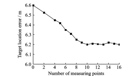
Fig.6 Relationship between measurement point and location error
In order to verify the practicability of the method, the UAV aerial data is used to verify the experiment. Firstly, according to Section 2.1, the camera was calibrated. The specific camera parameters are as shown in Table 4.

Table 4 Camera parameters
As shown in Figs.7(a)—(d), the UAV collects four images at four different measurement points. Fig.7(e) shows the ground target image. Table 5 is the measurement parameters of UAV and camera at different measuring points, in which the position and attitude of UAV are given by GPS and IMU, and the two pointing angles of camera are given by photoelectric measurement platform.

Fig.7 Images at four different measurement points and target point

Measuring pointLongitude/(°)Latitude/(°)Geodetic height/mRoll angle/(°)Pitch angle/(°)Yaw angle/(°)Azimuth angle/(°)Elevation angle/(°)A116.296 386 728.278 892 5567.612-0.8-2.389.10.189.4B116.297 064 628.278 906 8567.501-0.9-1.688.20.089.8C116.297 741 728.278 922 5566.362-0.2-1.288.8-0.290.0D116.298 418 328.278 929 4565.645-0.1-2.189.4-0.190.2
In order to show the superiority of the proposed algorithm, the target location algorithm based on the imaging model in Ref.[5] is used to locate the ground target when UAV atA,B,CandDmeasurement points, which can get the target position with only one measurement. Therefore, four location results can be obtained as shown in Table 6. On the other hand, the measured data atA,B,CandDare used for weighted least squares estimation, and the target position can also be calculated. In order to compare the error between the measured value and the real value, the target true position is obtained by RTK GPS, in which the location error is less than 5 cm. The results of the experiment are shown in Table 6.

Table 6 Location error of experiments
It can be seen from Table 6 that the target location error based on the imaging model is relatively large, which is due to the measurement area selected in this experiment is not flat. In contrast, the target localization accuracy of the proposed algorithm is significantly higher than that based on the imaging model, which is less affected by the terrain.
4 Conclusions
An UAV target location method using multiple observations is proposed and its key technologies are described. Firstly, the intrinsic parameters of the camera are calibrated, which can effectively reduce the imaging distortion. Through the multiple observations of the same target point, a constraint model between the observation point and the target point is established. The higher weight is given to the high-accuracy observation information, and then weighted least squares estimation is used to calculate the location of the target. The experimental results show that the method can effectively improve the precision of target location.
Acknowledgements
The work was supported by the National Natural Science Foundation of China (No.61601222), State Key Laboratory of Satellite Navigation System and Equipment Technology (No.EX166840046), the Natural Science Foundation of Jiangsu Province (No.BK20160789), and China Postdoctoral Science Foundation Funded Project (No.2018M632303).
杂志排行

Transactions of Nanjing University of Aeronautics and Astronautics的其它文章
- Analysis on Deflection Characteristics of Steel Cable-Stayed Bridge
- Nonlinear Control Method for Hypersonic Vehicle Based on Double Power Reaching Law of Sliding Mode
- Dynamic Analysis and Optimization of Pneumatic Wedge-Shaped Launcher for UAV
- Modal and Fatigue Life Analysis on Beam with Multiple Cracks Subjected to Axial Force
- Random Vibration of Steel Catenary Riser Conveying Fluid Under Wave Excitation
- Two Classes of Quaternary Codes from 4-valued Quadratic Forms