Working Mechanism of a Kind of Non-resonant Linear Piezoelectric Motor with Flexible Driving End
2018-11-21,,,,
, , , ,
1.School of Mechanical Engineering, Yancheng Institute of Technology, Yancheng 224051, P.R. China;2.State Key Laboratory of Mechanics and Control of Mechanical Structures,Nanjing University of Aeronautics and Astronautics, Nanjing 210016, P.R. China
Abstract: A non-resonant piezoelectric linear motor with a flexible driving end, which has an extensive working frequency range and good operation stability, is studied theoretically and experimentally. Based on the microscopic vibration characteristics of the motor stator, the longitudinal vibration model is established for the whole motor system. According to the Coulomb friction model and the motor vibration model, the friction mechanism of the non-resonant piezoelectric linear motor is investigated by dynamical analysis of the whole motor system. Furthermore, the vibration characteristics and mechanical output characteristics of the stator are simulated and experimentally studied on the basis of the friction drive mechanism model. Finally, both the simulation and experimental results show that this kind of motor remain stable in the frequency domain from 2.2 kHz to 3.5 kHz and that when the pre-stress is 4 N and the driving voltage is 90 V, the maximum velocity of the motor is above 4 mm/s and the maximum thrust is nearly 0.5 N.
Key words: piezoelectric motor; non-resonance; friction drive principle; flexible drive end
0 Introduction
Ultrasonic motors utilize the inverse piezoelectric effect of the piezoelectric element to activate the resonance of the elastomer (stator), and then utilize the friction of the interface between stator and mover to convert the micro-vibration of the stator into the macroscopic linear motion of the mover[1-3]. Therefore, the vibration characteristics of the stator and the friction coupling between stator and mover have a significant effect on the motor performance. By analyzing the vibration modes of the contact surface between stator and mover, many researches have been performed on the contact friction mechanism of the traveling wave type ultrasonic motor[4-6]and that of the standing wave type motor[7-8]. The friction interface of traveling wave ultrasonic motor is multi-point homogeneous contact, which has the characteristics of large contact area and continuous contact, therefore, this kind of motors have stable friction-driving performance. The friction interface of the standing wave type ultrasonic motor is single contact line or single contact point, with the characteristics of a small contact area and intermittent contact, resulting in that there is both shock and vibration in the running of the motor[9].
Resonant type ultrasonic motors have such advantages as high efficiency, large thrust weight ratio and self-locking characteristics, etc., and have a wide application prospect in precision position[10], optical instrument[11]and aerospace technology[12]. However, in order to obtain the desired vibration mode, the piezoelectric ultrasonic motor based on the resonant state must be rationally designed for the arrangement and excitation of the piezoelectric ceramic and for the structure of motor stator[13], so the stator structural design and the machining accuracy are in strict demand. At the same time, the resonant state is an unstable state, and the natural frequency of the stator will vary with temperature and other changes. In the vicinity of the resonant frequency, a slight change in the drive frequency could result in a significant change in the speed of the motor, which greatly affects the normal operation of the motor[14].
For the above reasons, the piezoelectric stacks are used for non-resonant motors to obtain the elliptical motion at the drive end of the stator, due to its large displacement output characteristic under non-resonant condition[15-16]. For non-resonant motors, the contact characteristics between stator and mover of the motor are similar to that of standing wave type ultrasonic motors, which have small contact area, contact discontinuity and various dynamic factors. Referring to existing research results of the friction-driven mechanism of the standing wave contact interface[9,17-18], the friction driving mechanism of non-resonant motors can be investigated by analyzing the longitudinal positive pressure and tangential friction on the interface between stator and mover.
It is found that the stator vibration and elliptical trajectory of non-resonant motor are completely different from that of the standing wave type motor. As for the standing wave type motors, the elliptical trajectory is mainly dependent on stator structure and excitation frequency and independent of the stiffness of the mover. With respect to non-resonance type motor, however, the elliptical trajectory and the motor performance are independent of excitation frequency. This is due to the fact that the piezoelectric stack has a highly accurate repeatability displacement output characteristic in a non-resonant state. Therefore, we will start from the vibration characteristics of the non-resonant linear motor to analyze contact forces between stator and mover. Furtherly, the friction driving mechanism of non-resonant linear piezoelectric motor will be researched according to the friction drive mechanism of standing wave linear ultrasonic motor.
1 Motor Structure and Its Ideal Model
Based on the high precision and large displacement output characteristics of piezoelectric stack, we propose a non-resonant piezoelectric laminated linear motor with flexible driving foot structure. The motor mainly includes the mover, stator, fixed base and clamping system, as shown in Fig.1. The clamping system, which includes three rollers, guides, putt and spring, is mounted on the base plate. Thus, the motor stator, which is mounted on the clamping system, can move in the direction perpendicular to the motion of mover.

Fig.1 Overall structure of motor
Since the mover is driven by the friction between mover and stator, the motor performance is greatly influenced by the contact state between stator and mover. Therefore, the clamping system needs to enable the adjustment of the contact condition effectively. As shown in Fig.1, the adjustment of contact condition can be achieved by putt and spring.
Simultaneously, in order to maintain the motor performance consistent to each other in both directions, the clamping system should have the ability to weaken the lateral forces between mover and stator generated in the preloading process. Therefore, the ideal model for this kind of motor, shown in Fig.2, should limit the lateral degree of freedom of the stator[19]. The method for limiting the lateral degree of freedom lies in the design of screws and disc springs, which can adjust the relative angle between the drive end and the mover namedτ, as shown in Fig.1.
Similar to the working principle of resonant ultrasonic motors, the trajectories of the motor-driven foot ends are also elliptical, as shown in Fig.2. Since the motor utilizes friction between stator and mover to achieve the linear motion of the mover, the motor performance is closely related to the longitudinal contact force, which means the contact force inydirection shown in Fig.2. Therefore, it is of importance to choose proper initial deformation of the preload spring for this kind of non-resonant piezoelectric motor.

Fig.2 Ideal structural model of motor[19]
2 Motor Stator Structure and Its Kinematics Model
The drive foot of the motor, as shown in Fig.3, is an approximately pentagonal structure with the pentagon bottom fixed on the support frame. The left and right sides are in direct contact with the piezoelectric stack system for displacement input. Its top is a flexible obtuse angle, which can achieve an amplified displacement output. Two piezoelectric stacks are installed symmetrically on both sides of the driving foot, and two wedges are used to achieve the pre-stress of piezoelectric stacks.

Fig.3 Overall structure of motor stator
The motion equations of drive end is
(1)
whereδ1andδ2represent the output displacements of the piezoelectric stacks.γandγ′ are the displacement magnification coefficients inxandydirections, which are caused by the flexible obtuse angle.
So the elliptical trajectory can be obtained at the drive end
(2)
whereAis the displacement amplitude of piezoelectric stacks.
Fig.4 shows that the motion on drive end (pointC) is a periodic elliptical trajectory while exciting piezoelectric stacks with two sinusoidal signals. The elliptical motion is crucial for achieving friction driving, therefore, the elliptical trajectories under non-resonant condition and the friction driving mechanism based on elliptical motion will be furtherly discussed in the following content.
Fig.4 The generation of elliptical motion
3 Longitudinal Vibration Model of Motor System
Due to the small amplitude of piezoelectric stacks, the vibration system can be simplified as follows: (1) The drive foot is simplified as a dumped mass; (2) Except for drive foot, the rest part of stator can be viewed as a whole mass, hereinafter called as “counterweight”; (3) The flexible part of drive foot and the piezoelectric stacks are simplified as an ideal spring; (4) The normal contact stiffness between stator and mover can be regarded as the stiffness of a linear spring.
Thus, the motor system can be simplified as two masses and three springs as shown in Fig.5. In Fig.5,m1andm2represent the mass of drive end and the counterweight, respectively.k1represents the stiffness of equivalent spring andk1=kt+ks, wherektandksrepresent the stiffness of the piezoelectric stack and drive foot, respectively.k3is the normal contact stiffness between stator and mover andk3=EcAc/hc, whereEc,Ac,hcrespectively represent the elastic modulus, contact area and thickness of the friction material between stator and rotor[20].Fy(t) is the equivalent output force of the piezoelectric stacks output force, which can be obtained from Eqs.(3),(4).
(3)

(4)
whereFmaxis the maximum output force of piezoelectric stacks,ωis the excitation frequency of piezoelectric stacks, andψis the phase shift of vibration.

Fig.5 Longitudinal vibration model of motor
Therefore, the vibration differential equation of the motor system can be expressed as

(5)
Then, we have
(6)

(7)
|Δ|=(k1+k3-ω2m1)·

(8)

(9)

(10)
whereA1is the amplitude of the drive foot,A2is the amplitude of the counterweight,B1is the offset of the drive end relative to the vibration balance position, andB2is the offset of the counterweight relative to the vibration balance position.
4 Non-resonant Friction Drive Characteristics of Motor
4.1 Contact friction model between stator and mover


Fig.6 Coulomb friction model of motor[9]
According to the coulomb friction model, the friction can be expressed as
(11)
whereεcis the viscous friction coefficient.
Due to the flexible drive foot, the initial deformation of stator driving is always larger than the output displacement of piezoelectric stacks. As a result, the motor stator and the mover are always in contact state during the whole working cycle. Then the vertical force between the stator and mover is
Fc=F0+k3yQsinωt
(12)
whereFcis the vertical force between the stator and mover,F0is the preload between the stator and mover, andyQis the vertical amplitude of drive end.
4.2 Mechanical properties of motor

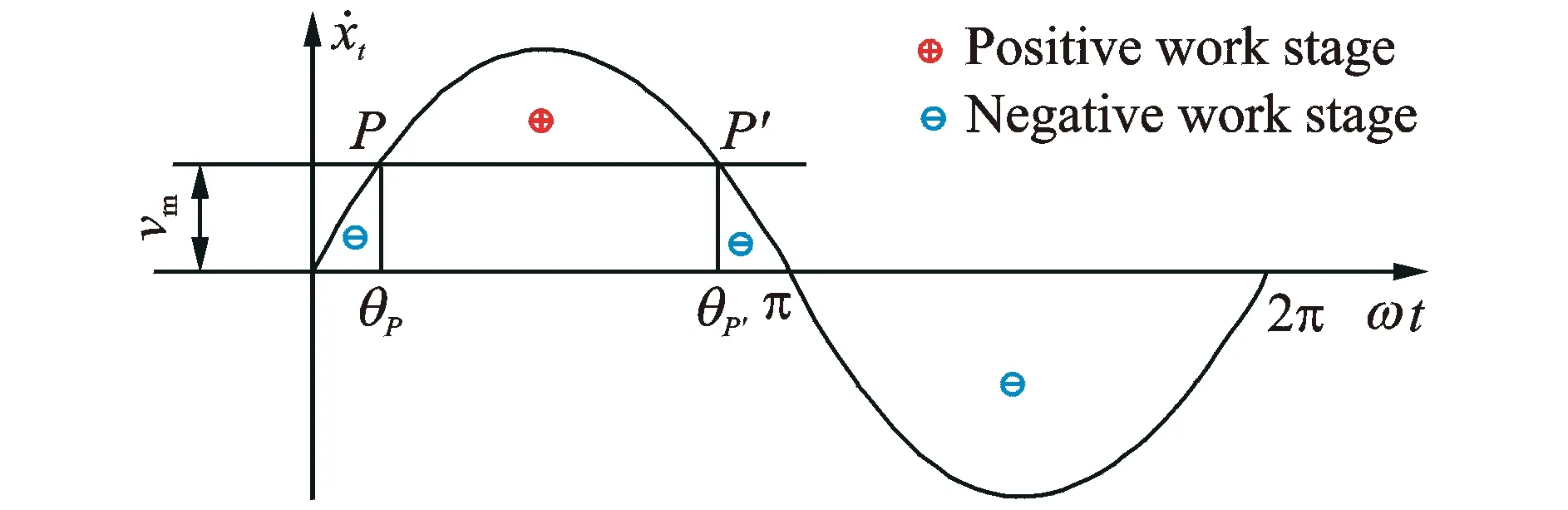
Fig.7 Work analysis of motor stator
Since the lateral vibration velocity of the stator is equal to the mover velocity at the pointsPandP′, the angles of pointsPandP′ are
(13)
wherexPis the amplitude component inxdirection.
In a working cycle, the energy loss caused by the rail friction can be neglected, and the interfacial frictional force between the external load and the stator is taken as the external force[9]. Since the mechanical energy of the motor mover does not change in a normal working cycle, according to work-energy theorem for systems, we have

(14)
whereFeis the average output force of motor.
Then, the average output force of the motor is

(15)
Substituting Eqs.(11), (13) into Eq.(15) yields

(16)
5 Simulation
In order to study the influence of the structural parameters of the motor on the stator vibration characteristics and the steady-state output characteristics of the motor, the vibration characteristics of the stator and the steady-state output characteristics of the motor are simulated and analyzed. Considering the stator structural parameters, the mass of drive end is taken as 0.01 kg and that of counterweight is 1 kg. The contact stiffness and the equivalent stiffness are viewed as constant, with the values of 2×10⁹N/m and 2×10⁶N/m, respectively.
5.1 Vibration characteristics of motor stator
Fig.8 shows the effect of the piezoelectric element stiffness on the longitudinal amplitude. It can be seen from Fig.8 that the motor stator resonates at a frequency of about 750 Hz and the amplitude of the drive foot is substantially constant at the frequency of 2.2 kHz to 3.5 kHz and is insensitive to dive end stiffness.

Fig.8 Influence of drive end stiffness on longitudinal amplitude-frequency characteristics
The drive end amplitude remains constant at a certain contact stiffness, as shown in Fig.9, but the amplitude decreases as the contact stiffness increases. And the amplitude with hard ceramic as friction material is nearly three times of that using epoxy based friction material.

Fig.9 Influence of contact stiffness on longitudinal amplitude-frequency characteristics
Fig.10 shows the amplitude-frequency characteristics of the stator with different mass of drive end. When the frequency is between 2.2 kHz and 3.5 kHz, the amplitude changes at a rate of 1%—3%. While the mass of drive end increases, the longitudinal amplitude results in an increases of less than 4%.

Fig.10 Influence of weight of drive end on longitudinal amplitude-frequency characteristics
As can be seen from Fig.11, the amplitude of the driving foot is almost constant at a frequency from 2.2 kHz to 3.5 kHz. The weight of the counterweight has little effect on the longitudinal amplitude of the stator drive side. When the weight is from 1 kg to 3 kg, the longitudinal amplitude maintains invariable.
Based on the above simulation results, it can be concluded that the longitudinal amplitude remains stable with the increase of frequency in the operating frequency range (2.2—3.5 kHz). Since the motor stator and the mover always maintain the contact state, the amplitude is about a few nanometers.
5.2 Motor mechanical characteristics
As for non-resonant type motors with flexible drive foot, the stator and mover are always in contact state, so the contact angle is approximately 2π over the whole working period. Fig.12 shows the motor output characteristics while changing the contact stiffness. It can be seen that the maximum output force of the motor becomes larger as the contact stiffness increases.

Fig.12 Influence of contact stiffness on mechanical properties of motor
Fig.13 shows the mechanical output characteristics of the motor at different excitation frequencies. It can be seen that the higher the excitation frequency, the greater the maximum output velocity of the motor. At a frequency range of 1—2 kHz, the speed of the motor is 3.6—5 mm/s. However, the excitation frequency has little effect on the maximum output power of the motor.

Fig.13 Influence of excitation frequency on mechanical properties of motor
Figs.14,15 show the mechanical characteristics of the motor for the lateral amplitude and the longitudinal. It can be seen from Fig.14 that under the same conditions, the greater the lateral amplitude of the motor stator, the higher the output speed of the motor, while the maximum thrust of the motor is almost constant. It can be seen from Fig.15 that the higher the longitudinal amplitude, the greater the maximum output power of the motor, but the velocity of the motor is almost constant.

Fig.14 Influence of lateral amplitude on mechanical properties of motor

Fig.15 Influence of longitudinal amplitude on mechanical properties of motor
Therefore, in the stator structure design, enlarging the vertical amplitude can get the larger output force and decreasing the lateral amplitude can get the smaller step distance resolution.
6 Experiment
In order to verify the vibration characteristics of the motor stator and the output performance characteristics of the motor, a motor prototype is fabricated and its main parameters are listed in Table 1.
Fig.16 shows the prototype of the motor. In the assembly process of motor stator, the sym-metry of the left and right piezoelectric stacking should be guaranteed. Meanwhile, the vertical tolerance of both levers of drive foot relative to the bottom of the clamping mechanism does not exceed 0.01 mm. In the motor assembly process, the stator clamping device needs to be adjusted accurately to keep the stator drive side and the mover in good contact.

Table 1 Main structural parameters of stator

Fig.16 Motor prototype photo
Since the driving force of the motor comes directly from the frictional force between stator and mover, proper preload is critical to the output performance of the motor. In order to obtain the appropriate preload, the preload adjustment experiment is required in the motor assembly process. Fig.17 shows the preload adjustment device. The motor is fixed on the workbench and LC1015 pressure sensor is installed between the end of stator and pre-pressure adjusting device. The value of the pressure sensor can be shown on the dynamometer with the measurement accuracy of 0.1 N. We utilized L-plate to press the pressure sensor and adjust the stator pre-pressure by changing its position.

Fig.17 Preload adjustment device
It can be seen from Fig.18 that the maximum motor speed is up to 2.5 mm/s when the pre-pressure is 4 N. Furthermore, while the pre-pressure is less than 2.5 N, the motor cannot work stablely, which lies in that too small pre-pressure results in abnormal contact condition between stator and mover.

Fig.18 Relationship between no-load speed and preload
However, since the contact angle is approximately equal to 2π, the preload between stator and mover should be less than 10 N, otherwise the motor mover will reciprocate in one cycle. The reason is that too high preload produce too large deformation in the contact interface between the stator and the mover, so that the friction characteristics are the same both in drive section and in return section.
The longitudinal amplitude characteristics of drive end can be measured with PSV-300F-B laser vibration measurement system. In the case of the excitation signal voltage peak-to-peak value of 100 V and the forward bias voltage of 50 V, the longitudinal amplitude-frequency response characteristics are measured as shown in Fig.19.

Fig.19 Amplitude-frequency characteristic of motor stator
As can be seen from Fig.19, when the excitation frequency is less than 2 kHz, the longitudinal amplitude of the drive end is not constant when the excitation frequency changes. When the excitation frequency is higher than 2 kHz, the longitudinal amplitude ranges from 0.5 μm to 0.7 μm.
The mechanical characteristics of the motor are simulated with the excitation voltage of 100 V, the excitation frequency of 2.5 kHz, the contact stiffness of 2×10⁹N/m and the viscous friction coefficient of 0.001. The precision hard ceramic is chosen as the friction material of the stator and the stator material is 45 steel. The mechanical strength test is carried out with the preload of 4 N. The simulation and experimental results are shown in Fig.20.

Fig.20 Mechanical characteristics of motor
From Fig.20, it can be seen that there are a little errors between the theoretical results and the experimental results. The experimental results show that the maximum velocity and the maximum thrust are slightly smaller than the theoretical simulation results. Because of the friction between the motor mover and rail slide, and the assembly error of motor stator, the motor performance is reduced. In general, the simulation can show the trends for motor performance and provide a method for prediction and optimization of this kind of motors.
7 Conclusions
We propose the vibration model and verify the working mechanism of a non-resonant friction driving linear motor. The performance of the piezoelectric linear motor is greatly influenced by the contact state between stator and mover. For the non-resonant motor, the clamping device not only provides a stable longitudinal preload for the stator, but also weakens the lateral force generated during the preloading process. Therefore, when pre-pressure is applied, the drive foot should have only a degree of freedom along the direction perpendicular to the direction of movement of the guide rail.
Similar to the resonant ultrasonic motor, the two piezoelectric layers are excited by two sinusoidal signals with a phase difference of π/2 to obtain the elliptical motion at the flexible drive end. Unlike the elliptical trajectory of the resonant ultrasonic motor, the elliptical trajectory is obtained by using the static large displacement output characteristic of piezoelectric stacks in a non-resonant state. Therefore, the elliptical trajectory mainly depends on the self-displacement output characteristic of the piezoelectric stack and the flexible amplification factor of the stator driving foot, and it is independent of the vibration mode of the motor. Thus the motor can operate stably in a wide operating frequency.
The frequency of the longitudinal vibration of the motor system is studied utilizing the longitudinal vibration model of the motor system. The simulation results show that the resonant frequency of the motor prototype is about 1 kHz. In the vicinity of the resonant frequency, the motor performance is quite different. However, when the motor operating frequency ranges from 2.2 kHz to 3.5 kHz, the motor’s vertical amplitude is almost stable and the motor can work stably in the frequency range.
The non-resonant contact kinetic model based on the Coulomb friction model is proposed in order to study the dynamic characteristics of the non-resonant linear motor. The simulation results show that enlarging the longitudinal amplitude can increase the motor thrust, however, the lateral amplitude has little effect on the motor thrust. The velocity of motor increases with the lateral amplitude of the drive end, while the effect of the longitudinal amplitude on the motor thrust is not obvious. At the same time, increasing the contact stiffness can improve the motor thrust and motor speed.
In addition, the appropriate pre-pressure between the stator and the mover has a significant effect on the motor performance, and there is an optimum pre-pressure for the motor to obtain the best performance of the motor. When the pre-stress is 4 N and the driving voltage is 90 V, the maximum velocity of the motor is up to 2.5 mm/s, the maximum thrust is 0.5 N and the displacement resolution is about 1 μm. The experimental results are in good agreement with the simulation results of the friction drive mechanism model. Compared with the existing non-resonant inertial impact piezoelectric linear motor, the output thrust of this type of motor increased by 50% and can be further improved through the optimization of structural design and the adoption of large displacement output piezoelectric stacks.
Acknowledgements
This work was supported by the National Natural Science Foundations of China (Nos.51405420, 51375224, 61503319), the Natural Science Foundation of Jiangsu Province (No.BK20140474), the Sponsorship of Jiangsu Oversea Research and Training Program for University Prominent Young & Middle-aged Teachers, the Jiangsu Province Ordinary University Professional Degree Graduate Innovation Project (No.SJZZ16_0294), and Qing Lan Project of Jiangsu Higher Education of China (No.Su-Teacher 2018-12).
杂志排行

Transactions of Nanjing University of Aeronautics and Astronautics的其它文章
- Analysis on Deflection Characteristics of Steel Cable-Stayed Bridge
- Nonlinear Control Method for Hypersonic Vehicle Based on Double Power Reaching Law of Sliding Mode
- Dynamic Analysis and Optimization of Pneumatic Wedge-Shaped Launcher for UAV
- Modal and Fatigue Life Analysis on Beam with Multiple Cracks Subjected to Axial Force
- Random Vibration of Steel Catenary Riser Conveying Fluid Under Wave Excitation
- Two Classes of Quaternary Codes from 4-valued Quadratic Forms