Forming Characteristics of Linear Charge with Curved Liner under Two-end Initiation
2018-11-12CHENXiLIUJieDUZhonghuaWANGKangkang
CHEN Xi,LIU Jie,DU Zhong-hua,WANG Kang-kang
(1.School of Mechanical Engineering, Nanjing University of Science and Technology, Nanjing 210094, China;2.Guilin University of Electronic Technology, Guilin Guangxi 541004, China)
Abstract:To improve the power of a linear explosively formed penetrator (LEFP), a new type of linear charge with curved structure was designed. Under a two-end initiation, the forming process of LEFP and influences of curvature radius on the process were investigated by numerical simulation method and a pulse X-ray photography experiment was carried out. The results show that the detonation wave collides under the two-end initiation, which causes the detonation wave to effectively converge toward the direction of LEFP movement and is beneficial to the closure of the curved liner. However, the larger the curvature radius, the harder the closure. LEFP is in good shape when it is stable, and the head velocity and utilization can reach 2100m/s and 87%, respectively. The test results verify the feasibility and effectiveness of the formation of a high-power LEFP for a linear charge with curved liner under the two-end initiation.
Keywords:linear-shaped charges; curved liner; detonation wave collision; two-end inititation; liner explosively formed penetrator; LEFP
Introduction
A linear explosively formed penetrator (LEFP) is a type of shaped charge that combines the linear cutting principle and the forming principle of an explosively formed penetrator. LEFPs have the characteristics of high flight stability, great penetration power and a noticeable crater. They are widely applied in the separation of spacecrafts, the opening of parachutes, blasting, cutting and armor protection fields[1-2]. Currently, the research focuses on the forming mechanism, initiation mode and structure design of LEFPs for a V-type charge liner structure[3-6]. However, the disadvantage of V-type charge is very obvious: the penetrator easily breaks and diverges at a large standoff distance[7]. Moreover, the penetration depth of LEFPs is not ideal for different shapes of penetrators under different initiation modes. Particularly, in the condition of two-end initiation, a "folded" LEFP will be formed, but the liner is linear in the direction of length; thus, the velocity gradient in the middle and at the two ends of the liner on the longitudinal section cannot effectively close the LEFP. This results in a very scattered shape and low utilization of liner, which cannot meet the requirements of penetration.
A linear charge with a curved liner structure is developed to improve the formation of LEFP. The linear charge with a curved liner is equivalent to bending an ordinary linear charge liner; thus, the liner has a constant curvature in the length direction, which improves the quality of liner. When the detonation wave collides, the liner can reverse and close not only in the width direction, but also in the longitudinal section due to the curvature in the length direction, which can greatly improve the convergence of detonation wave. Therefore, a well-formed LEFP in both width and length directions can be obtained. Furthermore, the detonation wave collision will produce an overpressure which is close to 2 times that of a non-collision position[8]. The pressure will promote the acceleration of liner and form a high velocity penetrator. The premise is that the two ends of charge detonate simultaneously to generate a detonation collision. A large deformation of the curved liner on the longitudinal section is the key to achieve both quality and velocity, to realize a great increase in LEFP power and to improve the penetration performance. However, the forming process of linear charge with a curved liner, the effects on the forming shape, the head velocity, time and flight distance of stable formation, the utilization of liner, power, etc., are not well understood.
This study focuses on the forming process of linear-shaped charge with curvature under a two-end initiation based on the detonation wave collision theory. The spherical wave collision pressure and the effect of curvature radius on the forming characteristics are analyzed and discussed through numerical simulation. A pulse X-ray photography experiment was performed to verify the free forming and moving process of linear charge with curved liner.
1 Numerical simulation
1.1 LEFP structure
The linear-shaped charge with a curved liner is mainly composed of a liner, a main charge, an initiation device, and a shell. The structure diagram is shown in Fig.1. Due to the effect of boundary sparse waves, the formed penetrator easily breaks in the width edge direction; therefore, a sub-caliber charge is adopted to obtain an excellent and powerful LEFP. Here,Lis the charge length,W′ is the charge width, andHis the charge height. A uniform liner thickness, denoted asT, is adopted. In the length direction, the curvature radius of liner isRa.RaandLcodetermine the central angleαin the length direction. The liner width isW, the central angle in the width direction isβ, and the thickness of shell ist1. Fig.2 shows the positions of initiation points for LEFP under the condition of two ends detonating simultaneously.
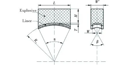
Fig.1 Structure diagram of linear charge with a curved liner
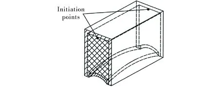
Fig.2 Diagram of positions of initiation points
1.2 Model setup
The finite element model consists of a liner, explosive, air and shell. To reduce the calculation amount and save solution time, a 1/4 model of linear-shaped charge with curved structure is established, as shown in Fig. 3. A fluid-structure interaction numerical simulation method is used. The liner, explosive, and air domain are meshed as an ALE grid, the shell is meshed as a Lagrange grid and the unit is taken as cm-g-μs. The meshing of liner adopted the four aliquots in the thickness direction. The computation time is set as 200μs, and the output interval of the calculation results is 4μs. The symmetry constraints are imposed on theXandZdirections of the model, and the boundary condition of the air is defined as a non-reflecting boundary.
The material of the liner is copper, the explosive is 8701 with a density of 1.70g/cm3, and the shell is made of 45#steel. The constitutive equation for material of the liner is selected as Steinberg, the equation of state for detonation products is selected as JWL, and the equation of state for air is selected as polynomial.
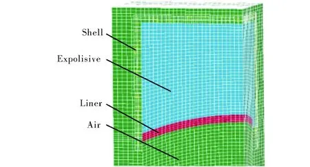
Fig.3 Element model
2 Simulation results and analysis
2.1 Pressure of detonation wave collision
When two detonation waves collide, the collision modes of the wave front are different owing to different collision conditions. Because the ratio of the length and height of the charge (L/H) is small, the detonation wave will collide in the form of a spherical wave. WhenL/His large, a stable slip detonation wave is formed and collides[9]. When two spherical detonation waves propagate on the face, the pressure at the point where the detonation waves collide increases rapidly. Two shock waves are formed and they propagate back to the detonation products on both sides at a certain angle. Owing to the different collision angles, detonation wave collisions and oblique collisions can occur. When the angle between the two detonation fronts is small, the flow deflection angle of the detonation product is consistent with the flow deflection angle of the reflected shock wave, and a reflection shock wave is generated at the collision point. With the increase in the angle between the two detonation waves, the two flow deflection angles increase. When reaching a certain angle, the flow deflection angle will be inconsistent, which can force the reflection shock wave to move up a certain distance from the collision point. The former is known as regular oblique collision, whereas the latter is called irregular oblique collision. The collision diagram of two detonation waves is shown in Fig.4.

Fig.4 Diagram of detonation wave collision
At different positions of the collision contact surface, the collision angles are different, and the pressures before and after collision are also different. Fig.5 shows the pressure contours of two spherical wave collisions and the positions of multiple pressure measurement points. It is noted that the collision effect is simulated on the cross section position of the charge structure. According to symmetry, half of the collision surface is measured. The two collision points are 40 mm apart, and a pressure measuring point is set every 2mm in the vertical direction of the contact surface of the detonation wave collision. It can be considered that the two detonation waves are colliding at measuring point 21, and oblique collisions are at measuring points 10-20.
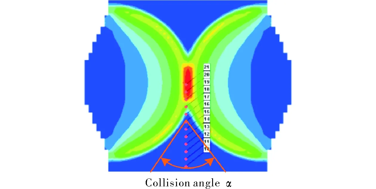
Fig.5 Cloud diagram of spherical wave collision pressure and measurement points
Fig.6 shows the pressure curve of a spherical wave collision obtained from the pressure measuring points. The pressure is minimum when the detonation waves are colliding. With the increase in collision angle, the collision mode is converted into a regular oblique collision, and the collision pressure gradually increases and can reach up to 76.3 GPa. According to the detonation wave collision theory, if the collision angle continues to increase, an irregular oblique collision is formed and the collision pressure will decrease. Therefore, there is a specific angle that can maximize the collision pressure. This angle is a transformation angle between the regular oblique collision and irregular oblique collision. Therefore, the collision angle is an important factor in determining the collision effect.
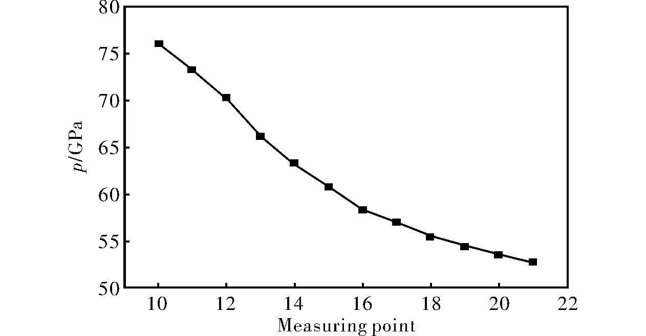
Fig.6 Pressure curve of spherical wave collision
2.2 Effect of curvature radius on the forming process
For a high-power LEFP, the formation on the longitudinal section will greatly affect the penetration ability. If it cannot be closed effectively, the specific kinetic energy will be smaller, and the penetration depth is not ideal, although the width of the crater is large. Meanwhile, the axial velocity of LEFP at steady state and the utilization of the liner can also be used as a basis for evaluating the penetration ability.

It can be observed that the deformation of the longitudinal profile of the curved liner generally goes through three stages: compression, reversal, and closure. After the two ends of the explosive are detonated, the liner at both ends first undergoes compression deformation and collapsing under the action of detonation products. When the detonation waves on both sides collide in the middle region of the charge length, the collision pressure in the middle portion increases sharply. This provides a driving force for the reversal and closure of the penetrator in the length direction, so that the center part of the accelerated liner moves and turns over to form a high velocity bulge. At this time, the liners at both ends are gradually converged by the high velocity movement in the middle part. However, the closing velocity is far less than the axial velocity, owing to the attenuation of the detonation wave and the influence of the boundary sparse wave. The axial velocity gradually decreases from the center to both sides, forming a velocity gradient. During the continuous flight, the head velocity begins to gradually decrease. A penetrator with a certain length, width and thickness is gradually formed until the head velocity of the penetrator becomes stable.
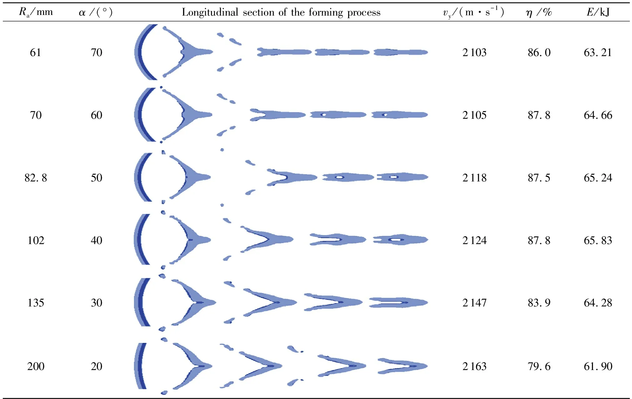
Table 1 Simulation results at different curvature radii Ra
When the curvature radiusRais smaller (the central angleαis larger), the radial velocity of the liner on both sides will increase in the longitudinal section. This can make the liner approach the middle more quickly and close properly. For a certain velocity of the detonation wave on the liner microelement, the axial velocity component will decrease due to the increase in the radial velocity component. However, the radial velocity is much smaller than the axial velocity; thus, the increment in the radial velocity is very noticeable during the closure of LEFP in the length direction. The reduction in the axial velocity is smaller than that ofVyand can be ignored. When the curvature radiusRabecomes larger (the central angleαis smaller), the shape of the liner is almost linear in the length direction. At this time, the radial velocity of the liner microelement becomes smaller, and the two ends of the liner are mainly driven by the head with high velocity motion and close to the middle part. Therefore, closure is more difficult and the closing time is longer. When the curvature radius is larger than a certain value, LEFP will not be completely closed in the longitudinal section. As indicated in Table 1, a continuous rod-shaped penetrating body is formed at 160μs, and the forming shape of the projectile is good. When the curvature radius is small, the formed penetrator is relatively longer and elongated. With the increase in curvature radius, the penetrator becomes wider and denser. However, when the curvature radius is larger than a certain value (such as 102mm), a cavity will be formed in the rear part of the penetrator and it cannot be closed properly.
The axial velocity of LEFP mainly depends on the collision pressure of detonation wave and the velocity gradient of the head and tail of LEFP. The utilization of the liner is related to the initial velocity gradient in the middle and both sides and the sparse waves on both sides. The change in the curvature radius has almost no effect on the collision pressure. Although the axial velocity at both ends of LEFP will be reduced with a smaller curvature radius, the reduction is extremely small relative to the axial velocity, and its effect on the axial velocity of the entire LEFP can be ignored. Therefore, the influence of curvature radius on the axial velocity is negligible, and the utilization of liner is smaller. The kinetic energy is determined by the mass and velocity of the continuous stable part of the penetrator. The higher the head velocity, and the greater the mass utilization rate of the liner, the greater the kinetic energy of the penetrator. When the curvature radius is 102mm, the axial velocity of LEFP can reach 2124m/s, the kinetic energy is approximately 65.83kJ, and the utilization of the liner is 87.8%. The formed LEFP is better in terms of shape, head velocity, kinetic energy, and liner utilization, which are beneficial to improve the power of LEFP.
3 Experiment
According to the simulation results, the combination of parameters with 102mm curvature radius of the linear charge with curved liner is selected and verified by an X-ray photography experiment. The experimental arrangement is shown in Fig.7. Two pulse X-ray machines were used to observe and record the forming process of linear charge with curved liner. Because the linear charge is centrally symmetric in shape, the formed LEFP under a two-end initiation has the same symmetry. However, the two pulse X-ray tubes are placed at different camera angles. One shoots in the horizontal direction, whereas the other shoots in the direction of isometric view of a similar oblique projection at the film projection angle, which is an angle of 60° between the two pulse X-ray tubes. In addition, different delay times are set to obtain two X-ray photographs of the forming LEFP at different periods. During the experiment, it is necessary to ensure that the two initiation points are synchronously detonated.
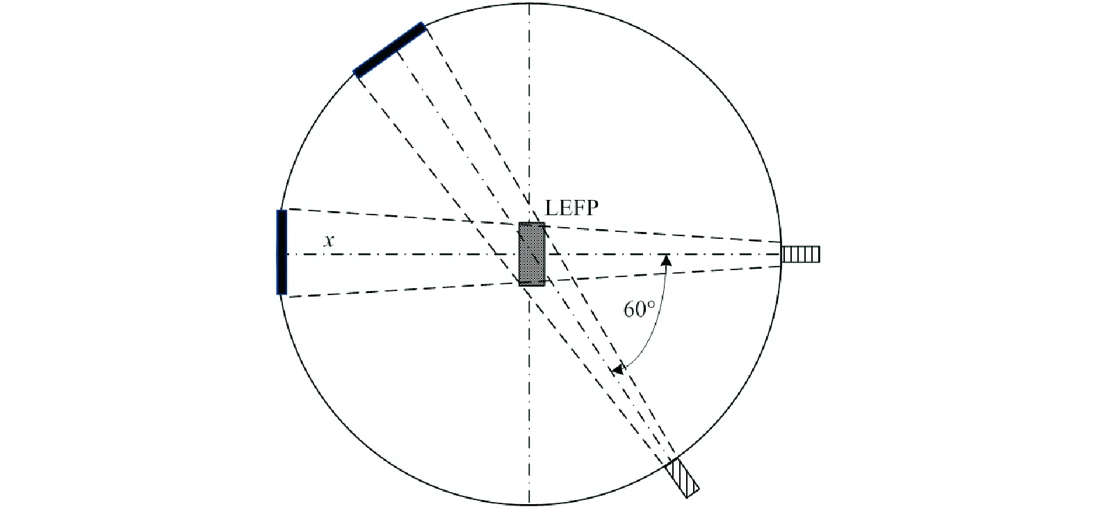
Fig.7 Experiment layout
The X-ray photographs of the forming penetrator at different periods and the corresponding simulation results are compared as shown in Fig.8. The left shows the X-ray photograph and the right shows the simulated shape at three different moments of the forming process. The periods in the X-ray photographs are 50, 75, and 175μs, respectively, whereas the simulation periods are 36, 72, and 160μs, respectively. Neglecting the deviation of the forming time, both shapes of the forming LEFP match well. At the initial time, as shown in Fig. 8(a), a head of high velocity bulge is formed in the middle part, similar to the shape of a swallow ail. With the forming of the projectile, two sides of the liner gradually converge to the center. However, because of the actual charge technology, breakages and some gaps at 75μs and 175μs appear at the head and tail of LEFP in the experiment, as shown in Figs. 8(b) and (c). Compared to the head velocity of 2124m/s in the simulation, the measured velocity of the head is approximately 1450m/s, which is 31.7% less than the simulated velocity. It is mainly influenced by the quality loss of LEFP.
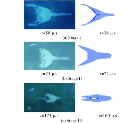
Fig.8 X-ray photographs compared to simulation results
4 Conclusions
(1) A curved liner structure was designed for the linear-shaped charge based on the detonation wave collision theory. Under the two-end initiation condition, the collision of two detonation waves can produce an overpressure and effectively converge toward the direction of the liner movement, which is beneficial to the closure of the curved liner, and achieve a well-formed LEFP with high velocity.
(2) The finite element model of the linear charge with curved liner was established. The simulation results show that the larger the curvature radius, the more difficult the closure, and the longer the closing time. However, the influence of curvature radius on the axial velocity is negligible, and the utilization of liner is smaller. The axial velocity and utilization can reach approximately 2100m/s and 87%, respectively, which is beneficial for improving the LEFP power.
(3) The results of the pulse X-ray photography experiment show that the shapes of the forming penetrator are similar to those of the simulation results at three different periods, which verifies the feasibility of the curved liner structure of the linear charge.
