Immobilization of PANI on Mesoporous Carbon: Preparation and Supercapacitor Performance
2018-10-11,u,,
,u , ,
1.Urban Vocational College of Sichuan, Chengdu 610101, P.R. China; 2.Institute for Clean Energy & Advanced Materials, Faculty of Materials and Energy, Southwest University, Chongqing 400715, P.R. China
(Received 27 May 2018; revised 7 July 2018; accepted 9 July 2018)
Abstract:Polyaniline (PANI) was effectively immobilized on the surface of ordered mesoporous carbon (OMC) by using Mn2O3as sacrificial template. The observed microstructure and morphology indicate that a thin layer of PANI was coated on OMC uniformly. As a supercapacitor electrode material, the discharge capacity of the optimized PANI/OMC could reach 467 F/g, which is far higher than that of OMC, PANI and Mn2O3/OMC. Furthermore, PANI/OMC composites with different content of PANI are obtained by adjusting the amount of Mn2O3on OMC and their properties are characterized. The results show that a thin layer of PANI can improve the capacity of PANI/OMC composites effectively and the further increase of PANI reduces the capacity of PANI/OMC composites. The sacrificial template method presented here is beneficial to coating a layer of polymer on carbon materials, and the content of polymer layer can be controlled by adjusting the amount of Mn2O3in Mn2O3/OMC.
Key words:Mn2O3; sacrificial template; polyaniline (PANI); supercapacitor
0 Introduction
The much wider applications of electronic devices and the growing demand for secure energy resources have made novel energy storage device played an increasingly important role in people’s daily lives[1]. As a necessary and efficient energy storage device, supercapacitors have become the current hot spot in the research of energy and materials science, which have the characteristics of high power density, long cycle life, good stability, and environmental friendliness[2-3]. Supercapacitor combines the strengths of the conventional capacitors and batteries. According to the charge storage mechanism, supercapacitors can be classified into two categories, electrical double layer capacitors (EDLCs) and pseudocapacitors[4]. The former store charges by reversibly adsorbing ions in the electrolyte solutions onto the electrode surface and the later do through fast reversible redox reactions on the interface between the electrode materials and the electrolyte[5-6]. The performance of supercapacitor depends largely on the quality of the electrode materials, so to develop excellent electrode materials is a great challenge for the exploitation supercapacitors. Porous ordered mesoporous carbon (OMC) has been studied extensively as electrode materials for supercapacitors owing to its high surface area facile tailored pore structure, and excellent thermal and chemical stability[7-9]. However, their energy storage density is too low for many important applications[10].
In order to further enhance the specific capacitance of carbon-based materials, to hybrid with chemically active materials that can combine faradaic and double layer capacitive performance has made a stunning progress[11]. Polymer is a promising material to modify the carbon materials and enhance their faradaic capacity. As one of the conductive polymers, polyaniline (PANI) has excellent electrochemical reversibility, easy preparation and good environmental stability. However, as a supercapacitor electrode material, the cycling stability of PANI is not good enough in the doping/dedoping processes[12]. Therefore, incorporation OMC with conducting PANI seems to be an effective method for improving the performance of supercapacitors due to the synergic effect of PANI and OMC[13-14]. As for the preparation methods of PANI and OMC hybrids, many works have been reported including electrochemical recombination[15-16], micro-emulsion polymerization[17]and solution chemical polymerization[18-19]and template method[20-23]. All of them, sacrificial template method can help realize in-situ coating PANI on carbon materials effectively. Recently, Yang et al. synthesized PANI/SWCNT (Single-walled carbon nanotubes) hybrid using MnO2acted as sacrificial template. Mi et al. prepared PANI nanofibers using the organic fiber as sacrificial template (methyl orange/FeCl3) route, in which the template could be automatically removed with the reduction of Fe3+[12, 22].
In this paper, a simple and effective sacrificial template method was reported to prepare PANI/OMC composites. The typical preparation process was described in Fig.1. At the beginning, KMnO4as etching agent will react with OMC to form a Mn2O3shell wrapped on the surface of OMC, and then PANI would cover on OMC to replace Mn2O3in the following polymerization process. The electrochemical tests demonstrate the PANI/OMC composites can exhibit a relatively high specific capacitance of 467 F/g and long-term stability, which make it a competitive candidate as electrode material for future energy storage systems.

Fig.1 Illustration of process for preparation of PANI/OMC composite
1 Experiment
1.1 Reagents
Aniline was purified by distillation with zinc dust under vacuum before use and stored at 4 °C. All other reagents were analytical grade and were used as received without further purification.
1.2 Synthesis of Mn2O3/OMC
Mn2O3/OMC nanocomposites were synthesized by hydrothermal method. First, 0.1 g OMC was dispersed into 20 mL water under sonication for 30 min, and then KMnO4aqueous solution was added into OMC suspension and keep stirring for 2 h at room temperature. Finally, the mixed solution was transferred into a 50 mL Teflon-lined stainless-steel autoclave, sealed and maintained at 150 °C for 6 h. After the reaction was finished, the kettle was naturally cooled down to room temperature. The obtained black solid product was washed several times with distilled water and dried at 60 °C. The Mn2O3/OMC loaded with different amount of Mn2O3was prepared by using 10 mL KMnO4aqueous solution with different content, and the obtained products by using 0.1, 0.3, 0.5 and 0.6 g KMnO4were designated as Mn2O3/OMC-1,Mn2O3/OMC-3, Mn2O3/OMC-5, and Mn2O3/OMC-6 accordingly.
1.3 Synthesis of PANI/OMC and PANI
Suspension A was prepared by dispersing 30 mg Mn2O3/OMC in 30 mL deionized (DI) water under ultrasound. Solution B was mixed aniline into HCl aqueous solution and ensure that the system include 2.8 mmol/L aniline and 1 mol/L HCl after mixing. Then, keep Solution B in ice bath. PANI/OMC was prepared as following: Solution B was added into Suspension A quickly and kept stirring in ice bath for 6 h, the resulting product was washed with water and ethanol several times, and then dried at 60°C in vacuum.
In order to prepare PANI/OMC composites with different PANI content, Mn2O3/OMC with different amount of Mn2O3formed in the above experiment were used. The amount of Mn2O3/OMC was fixed, 30 mg, and following same process as above just added different amount of aniline (0.47, 1.42, 2.37 and 2.84 mmol, respectively) which was depended on the amount of Mn2O3in Mn2O3/OMC composites (the mass ratio of aniline: Mn2O3=6.28). The products were named as PANI/OMC-1, PANI/OMC-3, PANI/OMC-5 and PANI/OMC-6 corresponding to Mn2O3/OMC-1, Mn2O3/OMC-3, Mn2O3/OMC-5, and Mn2O3/OMC-6, respectively. Besides, pure PANI was prepared in the same way using ammonium persulfate (APS) as oxidant for comparison.
1.4 Characterization of materials
Powder X-ray diffraction (XRD, XRD-7000) was used to characterize the phase constitution of the materials. Fourier transform infrared (FT-IR) spectra were recorded on a Nicolet FT-IR 6700 spectrophotometer (Thermo Nicolet). The morphology and microstructure of the samples were investigated by field-emission scanning electron microscopy (FESEM, JEOL-7800F) and transmission electron microscopy (TEM, JEM-2100). Thermogravimetric analysis (TGA) data were collected by thermogravimetric analyzer (TGA, Q50).
1.5 Electrode preparation and measurement
85% active material, 10% acetylene black, and 5% polytetrafluoroethylene (PTFE) were mixed and then coated on SSWM (Stainless steel welde mesh) (1.0 cm× 1.0 cm) as working electrode. Each electrode contains approximately 2.5 mg of active material and the electrodes were dried at 60 °C for 6 h before test. The electrochemical performance was evaluated on an electrochemical workstation (CHI 660 C, Shanghai Chenhua Instrument Co. Ltd, China) in a three-electrode system in 1 M H2SO4. Platinum foil and saturated calomel electrode (SCE) were used as the counter and reference electrode, respectively. Specific capacitance was calculated by the following equations[24]
C= (IΔt) / (mΔV)
(1)
wherem(g) is the mass of active material, andI(A), Δt(s), ΔV(V),C(F/g) are the discharge current, total discharge time, potential drop during discharging and specific capacitance, respectively.
2 Results and Discussion
The structure and composition of the prepared samples were investigated by XRD. Fig.2(a) shows the XRD patterns of pure OMC, Mn2O3/OMC and PANI/OMC. The XRD pattern of the OMC exhibits a broad peak from 20° to 28° and follow a weak peak at 44°, suggesting that OMC is not well crystallized and composed of microcrystalline. Compared with the XRD pattern of OMC, the characteristic broad peak of carbon become weak and some new peaks appear at the XRD pattern of Mn2O3/OMC, which matches well with the standard XRD pattern of cubic Mn2O3(JCPDS No.41-1422). This suggests that OMC was expended partially and Mn2O3was formed and wrapped on the surface of OMC. As can be seen from the XRD pattern of PANI/OMC, the peaks of Mn2O3disappear and the characteristic peak of carbon become much broader and weaker than that of OMC, resulting from the present of the two characteristic broad peaks of HCl-doped PANI at 2θaround 21° and 26° as reported[25-27]. It demonstrated that during the polymerization process Mn2O3was expended out and PANI was coated on the surface of OMC instead of Mn2O3.
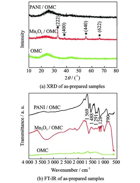
Fig.2 XRD and FT-IR of as-prepared samples
The surface properties of the obtained samples were further characterized by FT-IR (Fig.2(b)). No obvious infrared absorption peaks was observed from OMC. As for the Mn2O3/OMC, the peak appears at 3 500 cm-1assigned to Hydroxyl (OH) stretching vibration of the adsorbed water of the materials[28]. The peaks below 1 400 cm-1can be ascribed to fundamental vibrations of octahedral MnO6[29]and the peaks around 600—450 cm-1correspond to Mn—O bending vibrations[30], which indicate the existence of manganese oxide in the sample. After polymerization reaction, the characteristic peaks of Mn—O bond disappeared, and four sharp characteristic peaks of PANI located at 1 569, 1 488, 1 291 and 1 128 cm-1were observed in the FTIR spectrum of PANI/OMC. The peaks at 1 569 and 1 488 cm-1can be assigned to the stretching vibration of the quinoid ring and benzenoid ring, respectively[31]. The peaks at 1 291 and 1 128 cm-1ascribe to the C—N stretching of the aromatic amines rings. Further the N—H out-of-plane bending absorption also was observed at 790 cm-1[32]. These results suggest that the Mn2O3was expended out and the PANI was formed during the polymerization process, which are consistent with its XRD result.
The morphology and microstructure of the as-prepared samples were observed by using field emission scanning electron microscope (FESEM) and transmission electron microscope (TEM). It is clearly that the OMC illustrated in Figs.3(a1) and (a2) is relatively uniform ropes consisted by highly ordered carbon nanowires like reported in Refs.[33-34]. As can be seen from Fig.3(b1), OMC was wrapped with thick Mn2O3layer consisting of many nanoflakes and nanowires. The thick Mn2O3layer was further observed in Fig.3(b2), which could act as good templates for the formation and covering of PANI on OMC. Figs.3 (c1) and (c2) demonstrated that Mn2O3shell disappeared and OMC had been wrapped by PANI shell after the polymerization reaction. Compared Figs.3(c1) and (c2) with Figs.3(a1) and (a2), it was clear that a thin PANI layer successfully wrapped on the surface of OMC and replicated the ropes structure of OMC. From the above observation, in our experiment, OMC which covered by uniform Mn2O3layer could be formed by adjusting the raw ratio of OMC and KMnO4. In the following polymerization process, Mn2O3acted as oxidant and template reacted with aniline and formed PANI layer on the surface of Mn2O3/OMC instead of Mn2O3layer until Mn2O3was completely consumed. The combination between OMC and PANI in the proposed method is stronger than that of reported in Refs.[12, 27, 34], and the synergistic effect of OMC and PANI may has a great improving on the electrochemical performance of the PANI/OMC composites.
The content of Mn2O3in Mn2O3/OMC and PANI/OMC was investigated by TGA. As can be seen from Fig.4, as for the OMC/Mn2O3, the first weight loss of about 12% occurring from room temperature to 200 °C attributed to the desorption of H2O, followed an obvious weight loss (20%) located at around 250—600 °C, which could assign to the decomposition of OMC. Therefore, the content of Mn2O3in Mn2O3/OMC is about 68%. The TGA plot of PANI/OMC exhibits a 95% weight loss from 30 to 700 °C and 5% Mn2O3left, suggesting that most of Mn2O3has been consumed, acted as oxidant during the PANI polymerization process.

Fig.3 FESEM and TEM images of OMC, Mn2O3/OMC and PANI/OMC

Fig.4 TGA curves of OMC/Mn2O3and PANI/OMC
Cyclic voltammograms(CV) and galvanostatic charge/discharge(GCD) tests were employed to evaluate the electrochemical performance of all the samples obtained in this paper. Fig.5(a) displays CV curves of all samples at 5 mV/s with a potential ranging from -0.2 V to 0.8 V. Nearly rectangular CV curves were observed for the OMC and Mn2O3/OMC based electrode, while obvious redox peaks were found in the CV curves of PANI and PANI/OMC[35-36]. Two pairs of redox peaks (0.33/0.23 and 0.54/0.45, respectively) appeared in PANI/OMC-5 originate from the redox transitions between the leuco-emeraldine state and polaronicemeraldine state of PANI[37]. Among all the samples, PANI/OMC-5 deliver the highest current response, which indicates that the PANI coated on OMC can remarkably improve the capacitance behavior of OMC and PANI. GCD tests were further performed to evaluate all the samples. The symmetrical galvanostatic charge/discharge curves with slight IR (Infrared absorption spectrum) drops imply superior conductivity and reversible redox reaction (Fig.5(b)). The specific capacitance of OMC, Mn2O3/OMC, PANI and PANI/OMC calculated from the charge/discharge curves at a curret density of 0.5 A/g is 105, 146, 251 and 467 F/g, respectively. As shown in Fig.5(b), the specific capacitance of the PANI/OMC composites is higher than that of pure OMC, pure PANI, and Mn2O3/OMC composites, which indicated that decorating OMC with PANI is significant.The super conductivity, large surface area and double layer capacitance of OMC make it being a good supporting material.

Fig.5 CV and GCD curves of PANI, OMC, Mn2O3/OMC and PANI/OMC electrodes at a current density of 0.5 A/g

Fig.6 Specific capacity of PANI/OMC with different PANI content
Based on above results, in order to study the effect of PANI content in the PANI/OMC composites on their electrochemical capacitance, different amount PANI were introduced into PANI/OMC composites by adjusting the amount of Mn2O3in Mn2O3/OMC. When a small amount of PANI was introduced, there was a thin layer of PANI on the OMC substrate. As shown in Fig.6, with the increasing of PANI content, the specific capacitance of PANI/OMC increased, and PANI/OMC-5 reached a maximum capacitance of 467 F/g. Nevertheless, when more PANI was introduced, excess PANI particles would be free from the OMC substrate and the specific capacitance of PANI/OMC decreased. The specific capacitance of PANI/OMC composites above mentioned were 264, 333, 467 and 408 F/g at a current density of 0.5 A/g, respectively, and the PANI/OMC-5 composites obtained a maximum specific capacitance of 467 F/g, while the capacitance of OMC and pure PANI was only 105 and 251 F/g. These results indicated that incorporation OMC with PANI was an effective method for improving the supercapacitor performance of PANI/OMC composites due to the synergic effect of PANI and OMC.
The performace of PANI/OMC-5 was explored further.Fig.7(a) displays the CV curves of PANI/OMC-5 electrode at different scan rates,and all of the curves have two obvious pairs of redox peaks (0.33/0.23 and 0.54/0.45, respectively).The current densities of the redox peaks increase linearly with the scan rates, indicating the fast diffusion of the electrolyte in the electrode, which is benifited from the special porous structure of OMC. As shown in Fig.7(b), the nearly symmetrical charge-discharge curves and small resistance confirm their excellent capacitive properties.The areal specific capacitances of PANI/OMC-5 electrode are calculated to be 457 F/g at 0.5 A/g, 402 F/g at 1 A/g , 367 F/g at 2 A/g, 332 F/g at 5 A/g and 294 F/g at 10 A/g. In general, PANI/OMC-5 composites prepared from Mn2O3/OMC do processes good electrochemical properties.
The cycling stability was one of the important indexes to evaluate electrode materials. Fig.8 showed the change of the capacitance of the PANI/OMC-5 with the increase of cycle numbers. At first, there was a sharp decline of the specific capacitance of PANI/OMC-5 possibly because of the dissolution of residual Mn2O3corresponding to the TGA data. The specific capacitance even rose a bit after the electrode became stable gradually. In all, a capacity fade of 9 % was observed after 5 000 charge/discharge cycles for this composite. This result revealed that these kind of active materials had good capacitive properties with high electrochemical stability.
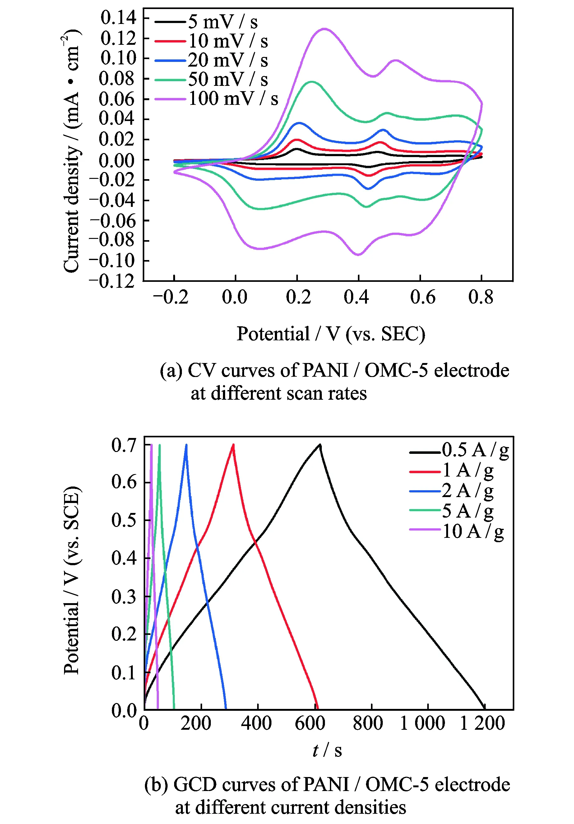
Fig.7 CV and GCD curves of PANI/OMC-5 electrode at different scan rates and current densities

Fig.8 Cycle performance for PANI/OMC-5 electrode at current density of 1 A/g
3 Conclusions
The PANI/OMC composite was successfully fabricated by a sacrificial template method. A thin PANI layer was wrapped on the OMC and the content of PANI could be controlled by the amount of Mn2O3in Mn2O3/OMC. The electrochemical results demonstrated that the PANI/OMC composite had better capacitive characteristics than that of pure OMC, pure PANI and Mn2O3/OMC. With the increase of PANI content, the specific capacitance of PANI/OMC increased first and then decreased, reaching a maximum capacitance of 467 F/g at a current density of 0.5 A/g when introduced PANI covered on the OMC substrate completely and no free PANI particles existed. The excellent cycle life of PANI/OMC composites may thanks to its stable hierarchy architecture. Therefore, the PANI/OMC composites developed here is a promising candidate electrode for supercapacitors.
Acknowledgements
This work was financially supported by Chongqing Key Laboratory for Advanced Materials and Technologies of Clean Energies, Institute for Clean Energy & Advanced Materials (Southwest University); the Natural Science Foundation of Chongqing (No.cstc2013jcyjA5004); the Fundamental Research Funds for the Central Universities (No.XDJK2013B031); Program for Excellent Talents in Chongqing (No.102060-20600218); and the National Natural Science Foundation of China (No.21163021).
杂志排行

Transactions of Nanjing University of Aeronautics and Astronautics的其它文章
- Local Path Planning and Tracking Control of Vehicle Collision Avoidance System
- Modeling and Optimal Design of Planar Linkage Mechanism of Coupled Joint Clearances for Manufacturing
- A Cause-Selecting Control Chart Method for Monitoring and Diagnosing Dependent Manufacturing Process Stages
- Adaptive Energy Efficient Power Allocation Scheme for DAS with Multiple Receive Antennas
- Solar Cells Based on All-Inorganic Halide Perovskites: Progress and Prospects
- Facile Fabrication of Hierarchical Porous N/O Functionalized Carbon Derived from Blighted Grains Towards Electrochemical Capacitors