System-Level EMC Assessment for Military Vehicular Communication Systems Based on a Modified Four-Level Assessment Model
2018-08-28PingZhouYinghuaLvZhihongChenHongpingXuSchoolofElectronicEngineeringBeijingUniversityofPostsandTelecommunicationsBeijing00876China
Ping Zhou*, Yinghua Lv Zhihong Chen, Hongping Xu School of Electronic Engineering, Beijing University of Posts and Telecommunications, Beijing 00876, China
2 Beijing Institute of Astronautic System Engineering, China Academy of Launch Vehicle Technology, Beijing 100076, China
* The corresponding author, email: ana0072@163.com
Abstract: With the development of EMC technology, EMC assessment has become increasingly important in EMC design. Although numerous EMC assessment models are available today, few of them can provide a tradeoff between efficiency and accuracy for the specific case of military vehicular communication systems. Face to this situation, a modified four-level assessment model is proposed in the paper. First, the development of EMC assessment technology is briefly reviewed, and the theoretical mechanism of EMI environment is introduced. Then, the architecture of the proposed model is outlined, and the assessment methods are explored. To demonstrate the application of it, an example involving a communication system in a military vehicle is presented. From the physical layer to the signal layer, a hierarchical assessment on the entire system is successfully performed based on the proposed model, and we can make a qualitative EMC assessment on the EMC performance of the system. Based on a comparison with the traditional model, we conclude that the proposed model is more accurate,more efficient and less time-consuming, which is suitable for the EMC assessment on military vehicular communication systems. We hope that the proposed model will serve as a useful reference for system-level EMC assessments for other systems.
Keywords: military vehicular communication system; system-level; electromagnetic compatibility (EMC) assessment; four-level assessment model
I. INTRODUCTION
With the current trend of incorporating numerous electronic devices into systems, make an assessment and prevention of electromagnetic interference (EMI) [1-5] in a system have aroused much concern. In most practical cases, such EMI environments can lead to many electromagnetic compatibility (EMC) problems [6,7], such as degraded the communication quality, disruption of normal communication and decreased the system performance[8-10]. Thus, it is crucial for system users to control the potential sources of EMI [11-13].To this end, performing a system-level EMC assessment of the system to predict the potential EMI environment is of great important[14,15].
The development of system-level EMC assessment technology can be traced back to the 1960s [16,17], when several EMC assessment models were proposed, such as the IAP model [18], the IEMCAP model [19,20], and the ACAT model [21,22]. Among them, one of the most classical models is the traditional four-level assessment model [23]. As its name implies, the architecture of the traditional model is designed into four hierarchical levels.Byfirst performing a rough assessment based on the signal amplitude, the least likely potential EMI sources can be eliminated directly.Next, the second-level EMC assessment is performed based on the spectral analysis, and detailed prediction and performance analysis are performed as the third and the fourth levels of the EMC assessment process. The potential EMI environment in the system can be identified based on the assessment results and the EMC performance of the entire system can then be predicted based on the overall result. By means of this hierarchical assessment method, the efficiency of EMC assessment can be significantly increased and the time consumption can be decreased dramatically.Because of its remarkable advantages, the traditional four-level assessment model has been widely used for many years. With the rapid development of technology, however, the traditional model has become limited, outdated and insufficient, especially for the military vehicular communication systems. None of those existing models is currently suitable for application to communication systems of this specific application type. Consequently, EMC problems have become inevitable, in this context, and the ability to perform an EMC assessment based on the potential EMI environment has become increasingly important.
To address this situation, we propose a modified four-level assessment model for system-level EMC assessment of the military vehicular communication systems. Although the architecture of the proposed model is similar to that of the traditional model, the EMC assessment methods applied on each level are completely different. In accordance with the specific characteristics of military vehicular communication systems, the four hierarchical assessment levels in the proposed model are designed into the working condition assessment level, the working frequency assessment level, the signal power assessment level and the signal quality assessment level, respectively. Each level has its own assessment criterion and assessment method. Through these four levels of EMC assessment, one can rapid make a qualitative EMC assessment on the performance of the communication systems in military vehicles. The assessment methods applied on each level of the proposed model are more complex than those applied in the traditional model, however, the proposed modified four-level assessment model yields more accurate assessment results and allows the EMC assessment to be performed in less time,and it is also more practical and more efficient than other models for this specific case. From the physical layer to the signal layer, one can perform a detailed hierarchical assessment on the performance of a system. Through such an EMC assessment, one can rapidly make a qualitative assessment on the EMC performance of the entire system, which is helpful for the system-level EMC assessment on the system and will also be beneficial for guiding the future efforts regarding EMC design to the system.
The rest of this paper is organized as follows. The theoretical mechanism of the EMI environment is explained in Section 2. Then the modified four-level assessment model for communication systems in military vehicles is presented in Section 3, including the architecture of the proposed model and the assessment methods applied on each level. Then, an application example is presented in Section 4. The performance of the proposed model is compared with that of the traditional model in Section 5. Finally, some conclusions are presented in Section 6.
II. THEORETICAL MECHANISM
In practical cases, a military vehicular commu-nication system usually includes several electronic devices, such as HF radios, VHF radios,GPS navigators and other devices. The mutual influence of these devices will inevitably lead to a complicated electromagnetic environment in the system and may generate various types of EMI, such as fundamental wave interference, high-order harmonic wave interference and high-order intermediation interference[24,25].
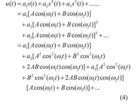
Suppose that the original transmitted signal in the system is s(t), with the form represented in Equation (1). Due to the mutual influence among the electronic devices in the system,s(t) is subjected to the mutual effect gain G[s(t)] expressed in Equation (2), where the aidenote the power coefficients of the devices. Under the mutual influence of G[s(t)],s(t) can be modified into u(t), as expressed in Equation (3). By taking the power series expansion of u(t) in terms of s(t), we can express thefinal signal as a sum of various additional signal components, as shown in Equation (4)and table 1 [26,27].

As can be seen in table 1, some additional signal components are generated beyond the original signal s(t) [28], namely, a fundamental wave component, some high-order harmonic wave components and some high-order intermediation components. The amplitudes of the additional signal components are determined by the amplitudes A and B of s(t) and the power coefficients aiin the mutual effect gain.The values of thedecrease with increasing i, and the amplitudes of the high-order signal components have the same tendency as that of the. In general, the power density of the additional signal components is mainly concentrated at lower orders. Therefore, in table 1, only some additional signal components of second and third order are listed. In a communication system, if one of these additional sig-nal components falls into the received bandwidth of the system, then an EMI environment will be generated.
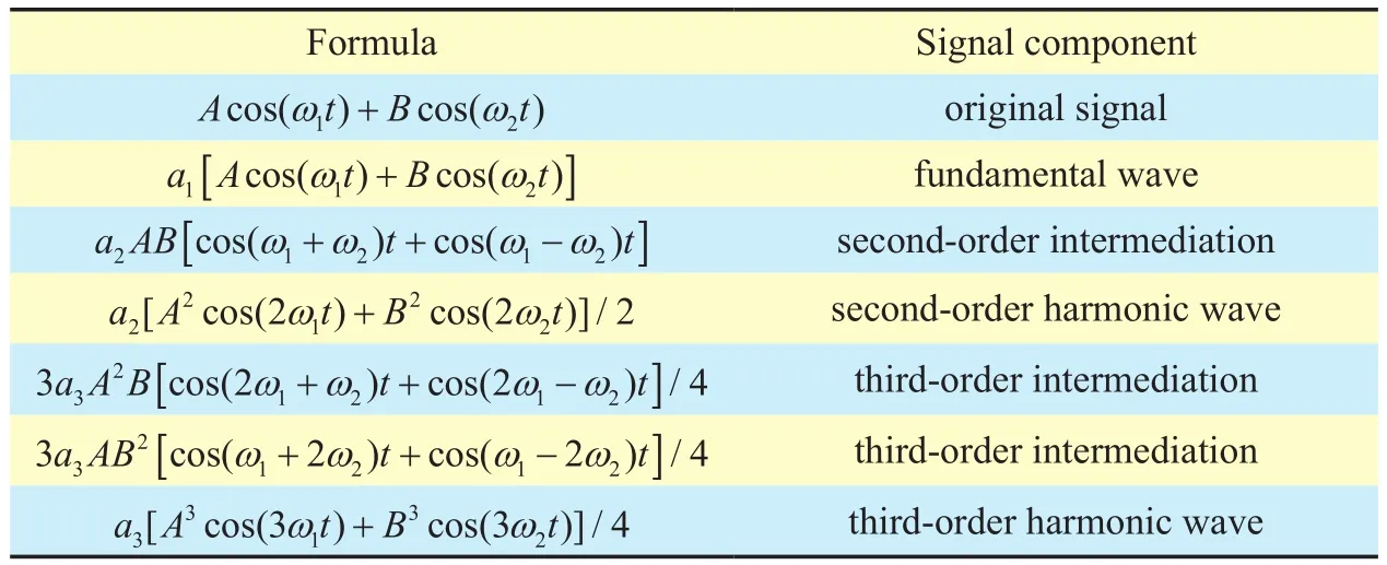
Table I. The main additional components of the signal.
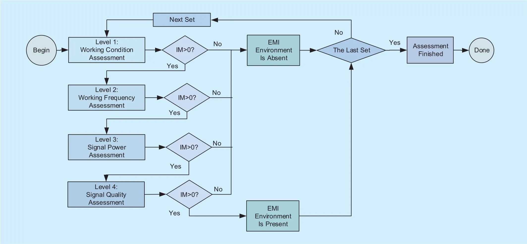
Fig. 1. Flowchart of the proposed model.
III. THE PROPOSED MODEL
For a system-level EMC assessment, the assessment criterion shouldfirst be identified. In the proposed model, the interference margin(IM) is defined as the assessment criterion.Depending on the assessment result at each level according to the IM, the EMC performance of a system can be classified into three grades with respect to an EMI environment:Presence, Uncertainty, or Absence. IM>0 indicates that the potential EMI environment is present, whereas IM=0 implies that the presence of EMI is uncertain, and IM<0 means that the potential EMI environment is absent.The proposed model is focused on the EMC performance of communication systems in military vehicles. Following the proposed model, one can perform a qualitative EMC assessment on the EMC performance of the entire system, which is of great importance for the EMC design of the system.
The flowchart of the proposed modified four-level assessment model is presented in figure 1, which shows the four levels of the hierarchical architecture. Based on the proposed model, an EMC assessment can be performed as follows:
Step 1: Choose a set of devices (e.g., a transmitter and a receiver) in the communication system.
Step 2: Perform the Level 1 assessment,which focuses on the working conditions.Several conditions that reflect the physical characteristics of the system are used to define as the IM criterion on Level 1. If any of the specified conditions is satisfied, then the IM will be identified as IM>0, which indicates that a potential EMI environment is present for this device set, and the EMC assessment will then proceed to the next level. Otherwise, the assessment of this device set will befinished.
Step 3: When IM>0 on Level 1, the second-level assessment should be performed on this device set, which focuses on the possibility of the frequency collision of additional signal components, and the IM criterion are defined in the form of the equations for identifying the presence of three types of EMI based on the working frequencies in the system. If any of the equations is satisfied, then the IM will be identified as IM>0, which indicates a potential EMI environment is present for this device set, and the EMC assessment will then proceed to the next level. Otherwise, the assessment of this device set will befinished.
Step 4: When IM>0 on Level 2, the third-level assessment should be performed on this device set. The EMC assessment focuses on the signal power and relies on an analysis of the coupling degree of signals. And the IM criterion on Level 2 is defined based on the sensitivity of the receiver. If the coupling degree of RF signals is higher than the sensitivity of the receiver, then the IM will be identified as IM>0, which indicates that a potential EMI environment is present for this device set, and the EMC assessment will then proceed to the next level. Otherwise, the assessment of this device set will befinished.
Step 5: When IM>0 on Level 3, the fourth-level assessment should be performed on this device set. The EMC assessment focuses on signal quality, and the IM criterion on Level 4 is defined based on a signal-tonoise ratio (SNR) threshold for analog signals or a bit error rate (BER) threshold for digital signals. The actual SNR or BER is calculated.If the actual signal SNR is lower than the SNR threshold or the actual signal BER is higher than the BER threshold, then the IM will be identified as IM>0, which indicates that a potential EMI environment is present for this device set, and the EMC assessment will then proceed to the next level. Otherwise, the assessment of this device set will befinished.
Step 6: When all levels of EMC assessment have been completed for a set of devices, the overall EMC assessment result is obtained.Then, if this is not the last set of devices to be assessed, the assessment will proceed to the next set of devices, and repeat the Steps 2 to 5,until no device sets are left to be assessed. If the assessment result for any device set in the system is IM>0, it is concluded that an EMI environment is present in the system.
3.1 Level 1: working condition assessment
On Level 1, the physical working conditions of the electronic devices in the system arefirst assessed, which include spatial and temporal conditions. The spatial conditions mainly reflect the spatial physical characteristics of the system, such as the spatial layout and the physical distance, whereas the temporal conditions reflect the temporal physical characteristics of the system, such as the possibility of run time collision. In the proposed model,the first-level EMC assessment depends on whether the layout space is crowded, whether the physical distance between the devices is limited and whether run time collision occurs between them. If any of these conditions is satisfied, then thefirst-level EMC assessment result will be IM>0, which indicates that a potential EMI environment is present, and it will be necessary to perform the second-level assessment.
3.2 Level 2: working frequency assessment
On Level 2, the EMC assessment focuses on the frequency collision problem in terms of the signal spectrum. In general, there are three types of spectral EMI that can arise from the signal components: fundamental wave interference, high-order harmonic wave interference and high-order intermediation interference. Therefore, the second level assessment is mainly focused on these types of interference,and the IM criteria are defined accordingly.These IM criterion equations pertaining to the presence of the potential sources of EMI environment are given as follows.
1) The IM criterion equation for fundamental wave interference is given by

where fTis the transmission frequency, fRis the received frequency, BTis the bandwidth of the transmitter, and BRis the bandwidth of the receiver.
2) The IM criterion equation for harmonic wave interference is given by

where BNTis the bandwidth of the n-th order harmonic wave of the transmitter and the order coefficient n is usually less than 5.
3) The IM criterion equation for intermediation interference is given by

where fT1and fT2are the transmission frequencies of two different transmitters, BNT1and BNT2are the corresponding bandwidths of the n-th order harmonic waves of these transmitters, and m+n is the synthetic order coefficient of the intermediation interference, which is generally less than 5.
The second-level EMC assessment is performed using the above equations. If any equation is satisfied, then the second-level assessment result will be IM>0, which indicates that a potential EMI environment is present, and it will be necessary to perform the third-level assessment.
3.3 Level 3: signal power assessment
On Level 3, the signal power of the RF signals of interest is considered, which is represented by their mutual coupling degree [29-31]. The equations for calculating the coupling degree of RF signals are presented below.
When only the influence of the transmitters is considered, the signal power of a transmitted signal is given by

where ptmis the transmitted signal power from the m-th transmission antenna, Ptis the total signal power of the transmitters, Lmis the power divide coefficient of the m-th transmitter, lmis the cable loss between the m-th transmitter and the m-th transmission antenna.
When the influence of the receivers is additionally considered, the signal power of a received signal is given by
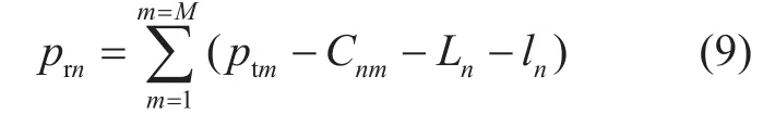
where prnis the received signal power at the n-th receiving antenna, Cnmis the coupling degree between the m-th transmission antenna and the n-th receiving antenna, Lnis the power divide coefficient of the n-th receiver, lnis the cable loss between the n-th receiver and the n-th receiving antenna.
Considering all of the electronic devices present in the system, the total signal power of the received signals is calculated as follows:

Here, Pris the total power of the received signals.
Therefore, the coupling degree of RF signals can be calculated as follows:
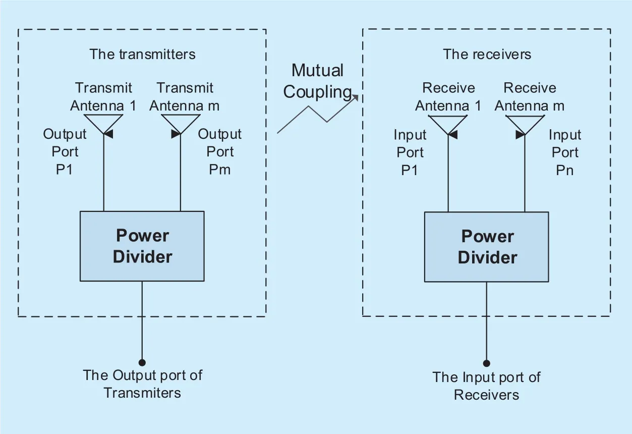
Fig. 2. Mutual coupling in the communication system.
where C, the coupling degree of RF signals between the electronic devices, represents the mutual coupling of RF signals in the system,as shown in figure 2. The higher the coupling degree, the higher possibility of a potential EMI environment is present.
On the third level, the coupling degree is calculated using the above equations, and the IM criterion is defined based on the sensitivity of the receiver in the device set that is currently under consideration. By comparing the coupling degree with this sensitivity, we can assess whether an EMI environment is present with regard to RF signals. If the coupling degree is higher than the IM criterion, then the third-level EMC assessment result will be IM>0, which indicates that a potential EMI environment is present, and it will be necessary to perform the fourth-level assessment.
3.4 Level 4: signal quality assessment
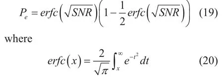
On Level 4, the EMC assessment is performed with a focus on communication quality in terms of SNR for analog signals or BER for digital signals [32].
On the one hand, for an analog communication system, the signal quality is assessed in terms of SNR, and the IM criterion for assessing the communication quality is defined based on the SNR threshold. In general, the actual SNR can be calculated using Equation(12). If the actual SNR is lower than the minimum SNR threshold, then the fourth-level EMC assessment result will be IM>0, which indicates that a potential EMI environment is present.

where S is the average power of the analogy signal, N is the noise power in the channel,and D is the distortion power of the analog signal.
On the other hand, for a digital communication system, the signal quality is assessed in terms of BER, and the IM criterion for assessing the communication quality is defined in terms of the maximum BER threshold. The BER can be calculated through a simulation analysis. If the actual BER is higher than the maximum BER threshold, then the fourth-level EMC assessment result will be IM>0, which indicates that a potential EMI environment is present.
In a system environment, many issues can make an influence on the signal BER, such as modulation type, channel coding mode, or the channel environment. Following are given some BER calculation equations based on the different modulation types:

Synchronization detection 2DPSK:
From the BER equations based on the different modulation types illustrated above, it is obvious that the signal BER is different when using different modulation type. The difference among them will be analyzed in the next Section. Also, the difference in the channel coding modes or the channel environment can also affect the signal BER result, which should be also considered in the signal quality assessment. As can be seen from the above BER equations, three different modulation types are listed, for the specific use case of the military vehicular communication systems that is considered here, FSK and PSK are the most commonly used modulation types.
In the signal quality assessment we performed, the channel environment is an influential issue on BER, and each of the channel environment models can be taken into consideration in the EMC assessment. Here, an AWGN channel environment model is considered as the basic system environment. As is known,the AWGN channel model is a basic channel environment model that mimics the effects of many random processes that occur in nature.It consists of a typical Gaussian channel, to which is only added the white noise that is intrinsic to the environment. If some other infl uential issues should be considered in a high complicated environment, such as the signal fading effect from mobility or obstacle, then the other channel environment models will be considered. However, in order to emphasize the signal quality assessment between the transmitted signal and the received signal in the original EMC assessment with the proposed model, we choose the AWGN channel here as the channel environment model and make an EMC assessment, therefore only the white noise signal will be considered to be present in the channel environment in addition to the EMI signals.
IV. APPLICATION OF THE PROPOSED MODEL
With their special requirements, military vehicular communication systems are usually different from the commercial ones. In this section, we perform a system-level EMC assessment on a military vehicular communication system using the proposed model. In this application example, the system comprises multiple HF radios, multiple VHF radios, a digital computer and a GPS navigator. Some of the major functions of this military vehicular communication system are to continuously communicate with other vehicles via signals,to transmit or receive digital data to or from nearby, and to provide GPS navigation for the vehicle itself. Due to some sensitive issues, the detailed specifications of this military vehicular communication system are not provided in this paper.
4.1 Level 1: working condition assessment
In the application example, some working conditions of the devices in the system are assessed at the first level, which include the spatial conditions and the temporal condition.In practical cases, the electronic devices in a military vehicular communication system are usually mounted within a limited physical distance of each other, or within a crowed layout space. Furthermore, some of electronic devices in the system often operate simultaneously in certain cases, which will inevitably result in run time collision. Thus, in accordance with thefirst-level assessment procedure, we identify the EMC assessment result as IM>0, which indicates that a potential EMI environment is present in the system and that the assessment should proceed to the next level.
4.2 Level 2: working frequency assessment
On the second level, the assessment on the working frequency is performed on whether any spectral collision may occur among the signal components that could lead to an EMI environment. Some of the frequencies and bandwidths of the electronic devices in the sample system are listed in table 2. With the information listed in table 2, the working frequency assessment on Level 2 can be performed directly based on Equations (5), (6)and (7).
1) Assessment on fundamental wave interference
For the EMC assessment of fundamental wave interference, we choose transmitter A and receiver D as the first set of devices to consider. For this device set, the potential forfundamental wave interference is assessed based on Equation (5) as follows:

Table II. Frequencies and bandwidths of devices.
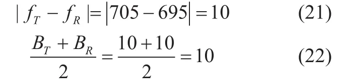
By comparing the results calculated in (21)and (22) with (5), we can predict that a potential fundamental wave interference is present for this device set. Then, to assess the other sets of the devices, a different transmitter and receiver is selected, and then we repeat the calculations until all sets of devices have been assessed. Finally, upon summing and analyzing all of the results, we determine that a fundamental wave interference environment is present. In accordance with this IM criterion,we identify IM>0.
2) Assessment on harmonic wave interference
For the assessment of harmonic wave interference, we choose transmitter B and receiver E as thefirst set of the devices to be considered and select n=2. The potential for assessment on the second-order harmonic wave interference is then assessed based on Equation(6) as follows:

By comparing the results calculated in(23) and (24) with (6), we can predict that a potential second-order harmonic wave interference is present for this device set. Then we increment the order coefficient n and repeat the calculations until all orders of interest have been analyzed. Subsequently, to assess the other sets of the devices, we select a different transmitter and receiver and again repeat the calculations until all sets of devices have been assessed. Finally, upon summing and analyzing all of the results, we determine that a harmonic wave interference environment is present. In accordance with this IM criterion,we identify IM>0.
3) Assessment on intermediation interference
For the assessment of intermediation interference, we choose transmitter A, transmitter C and receiver B, as thefirst set of devices to consider and select m=1 and n=1. The EMC assessment for the second-order intermediation interference is assessed based on Equation(7) as follows:

By comparing the results calculated in(25) and (26) with (7), we can then predict that the possibility of second-order intermediation interference is absent for this device set. Then we increment the order coefficients m and n and repeat the calculations until all the concerned high orders of interest are analyzed. Subsequently, to assess the other device sets, we select a different set of two transmitters and one receiver and again repeat the calculations until all sets of devices have been analyzed. Finally, upon summing and analyzing all of the results, we can determine that a potential intermediation interference environment is absent. In accordance with this second-level IM criterion, we identify IM<0.
Upon synthesizing all of the assessment results obtained above, we conclude that both a potential fundamental wave interference environment and a potential harmonic wave interference environment are present, whereas an intermediation interference environment is absent. In accordance with all the IM criteria,we identify IM>0, which indicates that some potential sources of EMI are present in the system and that the assessment should proceed to the next level.
4.3 Level 3: signal power assessment
As mentioned above, the coupling degree represents the RF signal power in the system can be calculated using Equations (8) - (11). Using these equations, we calculate the coupling degree of RF signals in the sample system. The calculated results are presented in figure 3.
The three curves in figure 3 represent the coupling degrees of RF signals between receiver D and each of the three transmitters A,B and C. The higher the mutual coupling degree is, the greater is the possibility that a potential EMI environment may be present in the system. As shown in figure 3, the frequency range from 600MHz to 1000MHz is represented on the x axis, and the calculated coupling degree is represented on the y axis. The black,red and green curves in figure 3 represent the calculated coupling degrees between receiver D and transmitters A, B and C, respectively.The A-D curve exhibits a high coupling degree, with a maximum value near 750 MHz,and the B-D curve shows a similar tendency to that of the A-D curve. By contrast, the C-D curve shows the lowest values of the coupling degree. While the sensitivity of receiver D,which is used to define the third-level IM criterion, is -38dBm. Therefore, in this application example, only those coupling degrees higher than -38dBm will result in an EMC assessment of IM>0. As shown in figure 3, the coupling degree does exceed the IM criterion of -38dBm at some points on these curves.Therefore, in accordance with the third-level IM criterion, we identify IM>0, which indicates that some potential sources of EMI are present in the system and that the assessment should proceed to the next level.

Fig. 3. Calculated result for the coupling degree.

Fig. 4. Simulation model of the communication link.
4.4 Level 4: signal quality assessment
As mentioned before, one of the basic functions of a military vehicular communication system is to maintain continuous communication with other vehicles via signals. Therefore,the EMC assessment on Level 4 focuses on the signal quality.
In the application example, the communication signals are the digital single-frequency audio signals. Therefore, the fourth-level analysis is conducted on the basis of the BER,and the IM criterion is defined based on the maximum acceptable BER. Table 3 lists some BER thresholds for digital signals. As listed intable 3, the maximum BER threshold for audio signals is Pe=1×10⁻³. Consequently, Pe=1×10⁻³is identified as the fourth-level IM criterion.

Table III. Standard BER thresholds for digital signals.
In practical situations, many factors contribute to the BER, such as the channel coding mechanism and modulation type. Consequently, both of these factors are discussed in this paper. For calculating the BER for audio signals in the application example, we choose some channel coding modes and modulation types that are commonly used in the military vehicular communication system and establish a simplified simulation model of a communication link. The model includes three signals,namely, the original transmitted signal and two interference signals, all of which coexist in the AWGN channel. The BER of audio signals can be calculated by comparing thefinal received signal with the original transmitted signal in this communication link. Figure 5 and figure 6 show the BER results for different channel coding modes and different modulation types, respectively.
1) The influence of the channel coding mode
Figure 5 shows the BER results for five channel coding modes: convolution coding,R-S coding, hamming coding, BCH coding and linear coding. In addition to the original transmitted audio signal, interference signals coexist with the original signal in the channel,with a certain level of attenuation. The straight red line in figure 5 represents the maximum BER threshold for distinguishable audio signals, and the broken colored lines represent the BER results for the received audio signals under thefive different modes of channel coding.
Figure 5 (a) and (b), show the BER results for different channel coding modes under the condition of BPSK modulation and QPSK modulation, respectively. The BER results obviously differ among these five modes of channel coding: the maximum BER is observed under the convolution coding, whereas the minimum BER is observed under the linear coding. As shown in figure 5 (a), the BER results for convolution coding and R-S coding are both higher than the BER threshold,whereas the BER results for hamming coding,BCH coding and linear coding are all lower than the BER threshold after a sufficient attenuation in 30dB to the interference signals. By contrast, the BER results for all five coding modes are above the BER threshold when the attenuation of the interference signals decreases to 20dB, as shown in figure 5 (b). Based on the BER results, the EMC assessment result on Level 4 is IM>0 for conditions under which the calculated BER is above the BER threshold, IM<0 for conditions under which the calculated BER is below the BER threshold and IM=0 for conditions under which the BER is equal to the BER threshold.
2) The influence of the modulation type
Figure 6 shows the BER results for four modulation types: FSK modulation, BPSK modulation, DPSK modulation and QPSK modulation. In addition to the original transmitted audio signal, some interference signals coexist with the original signal in the channel,with some level of attenuation. The straight red line in figure 6 represents the maximum BER threshold for distinguishable audio signals, and the broken colored lines represent the BER results for the received audio signals under four types of modulation.
Figure 6 (a) and (b) show the BER results for different modulation types under the condition of BCH channel coding and R-S channel coding, respectively. The BER results obviously differ among the four types of modulation: the maximum BER is observed under FSK modulations, whereas the minimum BER is observed under BPSK modulation. As shown in figure 6 (a), the BER results for FSK modulation and QPSK modulation exceed the BER threshold, whereas the BER results for DPSK modulation and BPSK modulation are below the BER threshold after a sufficient attenuation in 30dB to the interference signals. By contrast, the BER results for all four modulation types are above the BER threshold when the attenuation of the interference signals is 20dB, as shown in figure 6(b). Based on the BER results, the fourth-level EMC assessment result is identified as IM>0 for conditions under which the calculated BER is above the BER threshold, IM<0 for conditions under which the simulated BER is below the BER threshold and IM=0 for conditions under which the calculated BER is equal to the BER threshold.

Fig. 5. BER results for different channel coding modes.
Based on the above analysis, we conclude that in the considered scenario, the signal BER depends on the channel coding mode,the modulation type, and the level of signal attenuation in the channel. For this case, the BER results indicate that a potential EMI environment is present in the system (i.e., the signal BER is higher than the BER threshold)under certain conditions. Therefore, some efforts should be made in the subsequent steps of EMC design.
V. DISCUSSION
In Section 3, the architecture of the proposed model is outlined, and the assessment methods applied on each level are explored. And then an application example of the proposed model is presented in section 4. In this section, the performance of the proposed model is compared with that of the traditional four-level assessment model as follows:
1) First, we compare the models with respect to the accuracy. The EMC assessment that is performed based on the traditional model is mainly focused on the physical layer, and often pays little attention to the signal layer of the system. By contrast, the EMC assessment performed using the proposed model addresses both the physical layer and the signal layer,from the physical working conditions to the quality of individual signals, and thus can yield more accurate results.
2) In terms of practicability, the traditional model is suitable for analog communication systems. With the rapid development of electronic technology, however, most communication systems today have become digital systems, for which the traditional model is less effective. By contrast, the proposed model is suitable for application to both analog and digital systems and thus is more practical for modern systems.
3) Next, we consider the efficiency and time consumption of these two models. In the past, the traditional four-level assessment model could be applied with low complexity,high efficiency and little time consumption.However, for modern systems, the EMC assessments that can be performed using the traditional model are limited and outdated. For many modern systems, the traditional model can serve only as a rough assessment tool.By contrast, the proposed model is higher in efficiency and requires less time than the tra-ditional model when applied to a system with a complicated architecture.
4) Although the traditional model has been widely applied for many years, it is not suitable for the special case of military vehicular communication systems. On the other hand,the proposed model is more suitable for this particular case, but its range of application is somewhat limited. With more detailed work in the future, this new methodology can be extended to other types of systems to broaden its range of applicability, thereby also improving its usefulness.
In summary, each model has its advantages and disadvantages. In this paper, we proposed a modified four-level assessment model that is particularly well suited to the specific case of military vehicular communication systems.For other cases, a suitable model should be selected in accordance with the characteristics of the system.
VI. CONCLUSION
In this paper, a modified four-level assessment model for assessing the potential EMI environment in a military vehicular communication system is proposed. Using this hierarchical assessment method, one can rapid perform a qualitative assessment on the EMC performance of the system. An application example of the proposed model is also presented in this paper. In comparison with the traditional model, the proposed modified model is more accurate, more efficient and less time-consuming. By using the proposed model to perform a system-level EMC assessment, the EMC design cycle of a military vehicular communication system can be remarkably reduced.
In the near future, we intend to investigate the application of the proposed methodology to other communication systems, such as a Doppler frequency shift system and a hopping frequency system. Also, more influential issues on the channel environment will be considered in our future system-level EMC assessment research, such as the signal fading effect, the multipath effect or the Doppler effect in other channel environment models, which can make the proposed modified four-level selection model become morefit to the actual high complicated environment. This work can definitely be very helpful for enhancing the capability and applicability on the application of the system-level EMC assessments to other complex communication systems.
ACKNOWLEDGEMENTS
The authors gratefully acknowledge the anonymous reviewers who read our drafts and gave us many helpful suggestions. This work was supported by the National Moon Exploration Program of China (No. TY3Q20110020),also in part supported by the 13thFive-Year Community Technology Research Program of National Equipment Development Department of China (No.41409020301) and the National Natural Science Foundation of China(50971094).
杂志排行
China Communications的其它文章
- A Stackelberg Differential Game Based Bandwidth Allocation in Satellite Communication Network
- Joint Resource Allocation Using Evolutionary Algorithms in Heterogeneous Mobile Cloud Computing Networks
- A Master-Slave Blockchain Paradigm and Application in Digital Rights Management
- The Coevolutionary Relationship of Technology,Market and Government Regulation in Telecommunications
- Mobile Jammer-Aided Secure UAV Communications via Trajectory Design and Power Control
- A Quantitative Security Metric Model for Security Controls: Secure Virtual Machine Migration Protocol as Target of Assessment