Fluid Flow Past a Circular Cylinder with Tandem Rod and Staggered Rod at Low Reynolds Number
2018-08-28WUWenboandWANGJiasong
WU Wenbo , and WANG Jiasong,
1) School of Mechanical and Electric Engineering, Guangzhou University, Guangzhou 510006, China
2) School of Naval Architecture, Ocean and Civil Engineering, Shanghai Jiao Tong University, Shanghai 200240, China
(Received September 22, 2017; revised November 17, 2017; accepted May 21, 2018)
© Ocean University of China, Science Press and Springer-Verlag GmbH Germany 2018
Abstract The flow past a primary cylinder with one tandem control rod and one staggered control rod is simulated in this paper through solving the Navier-Stokes equations. Two examples are simulated to validate the model, and the results matched well with those of previous researches. The Reynolds number based on the diameter of the primary cylinder is 500. The diameter ratio between the control rod and the primary cylinder (d/D) is 0.25. It was found that the effect of the combination of one upstream tandem control rod and one staggered control rod on the hydrodynamics of the primary cylinder is a linear superposition of the effect of a corresponding single control rod, and the effect of the upstream tandem control rod is dominant at larger spacing ratios such as G/D = 2.For the combination of a downstream tandem control rod and a staggered control rod, the effect of the control rods is different from that of the corresponding single control rod in the region of 0.2<G/D<0.5 & 30˚<α<120˚ and 0.9<G/D<1.4 & 30˚<α<50˚, where the additional effect is obvious. In this case, the effect of the downstream tandem control rod is dominant at small spacing ratios (such as G/D = 0.1). At moderate spacing ratios such as G/D = 0.4, the effects of the tandem control rod and the staggered control rod are comparable in both cases.
Key words tandem and staggered control rods; additional effect of double control rods; vortex shedding; drag and lift coefficients;numerical simulation
1 Introduction
In offshore oil engineering, fluid flow past cylinderlike structures is a common phenomenon. Besides the main line that plays a major role in ocean engineering,some auxiliary lines are also located around such structures. As one of the classical problems of fluid dynamics,such flow has provided hints to some more complex problems.
Over the last several decades, fluid flow past an isolated cylinder has been widely studied, both experimentally and numerically. Many important in sights into this problem have achieved, as reflected in the reviews of Williamson (1996) and Norberg (2003). Although the geometry is simple, abundant flow features have continued to pique the interest of researchers (Grucelski and Pozorski, 2015; Rao et al., 2015).
The flow past cylinders in-group has different hydrodynamics or aerodynamic characteristics from the flow past an isolate cylinder (Sun and Gu, 1995). The interference between different cylinders was studied firstly in the issue of fluid flow past double cylinders. Many works have been done from different perspectives experimentally or numerically, as reflected in the reviews of Zdravkovich(1993), Nishimura (1986) and Sumner (2010). Many researchers have taken intensive measurements of the vortex-shedding frequency and the mean time-dependent force components on a rigid cylinder pair in various geometrical arrangements (Bearman and Wadcock, 1973; Zdravkovich, 1985). The flow patterns for two tandem circular cylinders with equal diameter in steady cross-flow are sensitive to both Reynolds number (Re=UD/ν, U is the velocity of the free stream, D is the diameter of the cylinder, νis the kinematic viscosity) and spacing ratio (P=G/D, G is the gap between two cylinders). Some different flow patterns have been identified in Igarashi (1984),Zhou and Yiu (2006), Carmo et al. (2010) and Wang and Zhou (2005). The flow structure and its downstream evolution are closely linked to the phase relationship between the gap vortices in the wakes of the cylinders (Hu and Zhou, 2008). The vortex-shedding frequencies of the cylinders are more properly associated with the individual free shear layer rather than with the individual cylinder(Sumner et al., 2000; Sumner and Richards, 2003).
It should be noted that the works on the two cylinders mentioned above are based on equal-diameter cylinders.Zhao et al. (2005, 2007) numerically investigated the viscous flow and turbulent flow past two circular cylinders with different diameters using a finite element method.The effects of the gap ratio and the position angle of the smaller cylinder on drag coefficient, lift coefficient and vortex-shedding frequency were discussed in detail. Firat et al. (2015) studied the pattern of flow past a square prism with one upstream staggered control rod. It was found that the flow pattern depends on the angle and the spacing ratio of the control rod.
In most studies, only one control rod or cylinder is located around the primary cylinder, and the effect of the single control rod on the primary cylinder was discussed.In Wu et al. (2016) and Lu et al. (2014), the combined effect of multiple control rods on the hydrodynamic characteristics of the primary cylinder was studied numerically. However, how the control rods collectively affect the hydrodynamic characteristics of the primary cylinder and which control rod plays the key role are not clear. In this paper, fluid flow past the primary cylinder with two control rods (one tandem control rod and one staggered control rod) at low Reynolds number is simulated, and the effect of the combination on hydrodynamic characteristics is discussed. To find out the role of each control rod in the combination, the case where only one control rod is located around the primary cylinder is also simulated. To discuss the difference between the effects of double control rods and a single control rod, the parameter termed ‘additional effect’ is proposed, and the variation in the ‘additional effect’ with the gap ratio and angle is investigated.
In this paper, the Reynolds number based on the diameter of the primary cylinder is 500, which is the same as that used in Zhao et al. (2005) and is greater than the critical Reynolds number of 200 (Williamson, 1988, 1989)for a three-dimensional model. Although three-dimensional models are preferable for investigating flow interaction between cylinders, the computational cost of threedimensional study is prohibitively high. Much previous research (Zhao et al., 2005, 2007) has used two-dimensional models to study the flow past cylinders for Re>200 and provided satisfactory prediction of the hydrodynamic characteristics of the cylinders. The two-dimensional simulations are carried out in the present study, and it is expected that they suit the major purposes of the study.The Reynolds number based on the diameter of the control rod is 125, which is much larger than the critical Reynolds number of 40 (Zdravkovich, 1997) for periodic laminar shedding. It is expected that the alternate vortices can shed from the control rod at any location.
2 Problem Description
The geometry configurations of the cylinder system are shown in Fig.1. Three different arrangements were used in this paper: one upstream control rod and one staggered control rod (Fig.1(a), called case 1), one downstream control rod and one staggered control rod (Fig.1(b), called case 2), one staggered control rod (Fig.1(c), called case 3).In Fig.1, the large cylinder is called ‘primary cylinder’,rod A is the tandem control rod, and rod B is the staggered control rod. The diameters of the primary cylinder and control rod are D and d respectively, the gap between the primary cylinder and the control rod is G, the angle of the location of the staggered rod is α, and the free stream velocity is U. As shown in Fig.1(a), the computation domain used here is rectangular. The left side is located 15D upstream of the primary cylinder and is defined as the velocity-inlet boundary. The right side is located 40D downstream of the primary cylinder and is defined as the outflow boundary. The top and bottom sides are located 15D from the primary cylinder and are defined as symmetry boundaries.
The spacing ratio G/D varies from 0.01 to 2. As the upstream control rod is placed, the angle α changes from 0˚ to 150˚, and the interval is 10˚. As the downstream control rod is placed, the angle α changes from 30˚ to 180˚,and the interval is 10˚. The diameter ratio (d/D) between the control rod and the primary cylinder is 0.25.
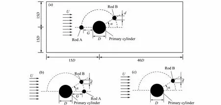
Fig.1 Sketch and definition of fluid flow over one primary cylinder and two control rods. (a) computational domain and numerical set-up for primary cylinder with one upstream rod and one staggered rod; (b) set-up for primary cylinder with one downstream rod and one staggered rod (c) set-up of primary cylinder with one staggered rod.
3 Governing Equations
The OpenFOAM code is used to compute the flow past the cylinder system. The finite volume method is used,which is based on the integration of the fluid variables on the control volumes. The governing equations of unsteady flow of viscous incompressible fluid in Cartesian coordinates can be expressed as follows:

where μ is the molecular dynamic viscosity, ρ is the density of the fluid, Uiis the velocity of the fluid corresponding to the ith direction, where i can be 1, 2 and 3,corresponding to x, y and z directions, and p is the pressure.
A second-order Gauss integration scheme with a linear interpolation for the face-centered value of the unknowns was used for the divergence, gradient, and Laplacian terms in the governing equations. The second-order backward Euler method was adopted for time integration.Thus, the numerical discretization scheme gave second order accuracy in space and time. The pimple Foam solver in the OpenFOAM is employed to solve the dynamic equations.
4 Validation
4.1 Grid Validation
To verify the influence of the computational grid on the numerical results, the computation of the configuration that the primary cylinder with one downstream tandem control rod and one staggered control rod (case 2, α=30˚,G/D = 0.2) was carried out. The mesh near the primary cylinder and control rods is shown in Fig.2. The structured grids were used here. The numbers of circumferential nodes on the primary cylinder and control rods are N and N/2 respectively. The radial mesh size of the first grid near the primary cylinder and control rods are δ and 3δ/8 respectively (the value of δ is shown in Table 1), according to the different diameters of the cylinders. Five different grids were used for the validation, and the parameters for these five grids are shown in Table 1. The hydrodynamic characteristics of the primary cylinder are listed in Table 2. It can be found that,(mean drag coefficient) and fs(vortex-shedding frequency) of the primary cylinder are precise enough in grid 3, and refining the mesh changed little in the simulation. Cl,rms(RMS lift coefficient) fluctuated around 0.364, which may have been due to the lift coefficient being highly sensitive to the shear layer separation near the cylinder. This was also encountered in previous works, such as in the results in Norberg (2003), Mittal and Balachandar (1997) and Rajani et al. (2009), where Re=300 showed such fluctuations. Therefore, we believe that the simulation based on grid 3 can give results with sufficient accuracy, and the simulations and discussions later in this paper are based on the mesh with the properties in grid 3.
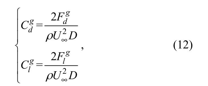
In this paper, the mean drag coefficient and the RMS lift coefficient are defined as
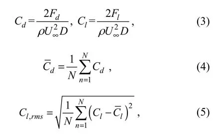
where U∞is the free stream velocity of the fluid, and Fdand Flare the drag and lift on the primary cylinder, respectively. N is the number of the data in integral multiple periods (the period is the reciprocal of the fs). To reduce the error, the data in twenty periods were used in this paper.

Fig.2 Grid generated around the cylinders.
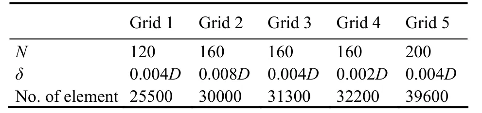
Table1 Mesh properties for different grids
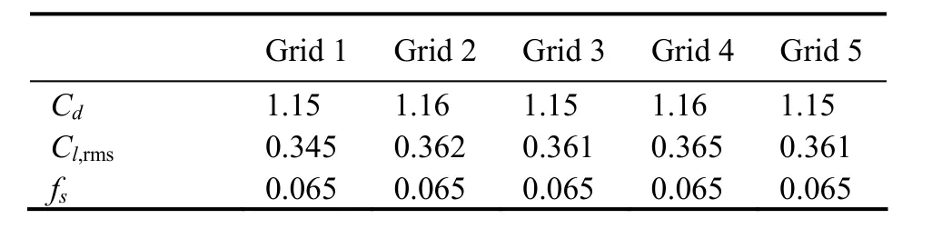
Table 2 Hydrodynamic character of the primary cylinder for different grids
4.2 Validation for Available Cylinder Configurations
To validate the numerical model and computational method in this paper, the results of the flow past a single circular cylinder at different Reynolds numbers and two staggered cylinders at different incidence angles were computed and compared with the results of previous research.
Validation1. Single cylinder
The comparisons of the mean drag coefficients and Strouhal numbers are shown in Fig.3. As Re ranges from 0 to 350, the drag coefficient decreases with increasing Re. The results computed in this paper match well with those in Zdravkovich (1997) and Rajani et al. (2009) but were slightly lower than those in Lei et al. (2000). The Strouhal number generally increased as Re changed from 50 to 300. The results here match well with those of Rajani et al. (2009) and Williamson and Roshko (1990),while the results in Lei et al. (2000) were slightly larger than these values.
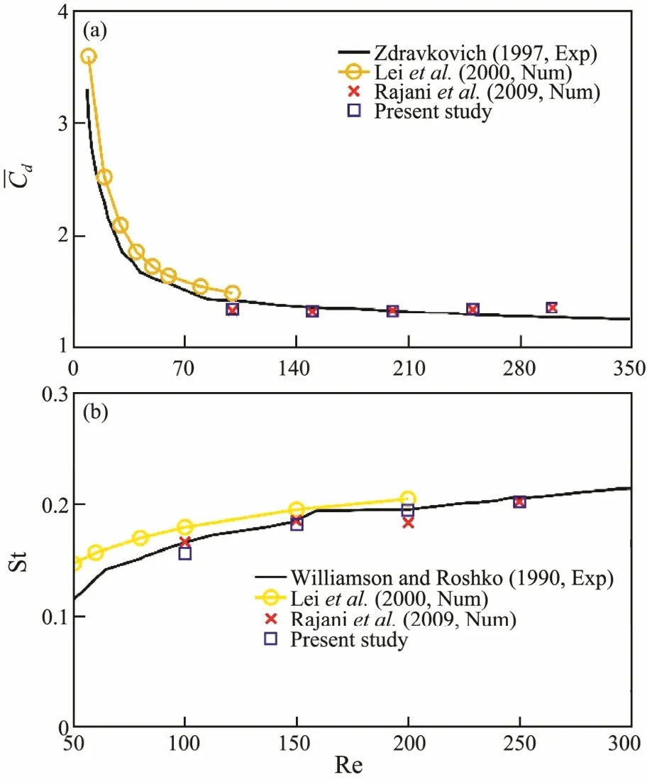
Fig.3 The mean value of drag coefficient and Strouhal number of a single cylinder at different Reynolds numbers. (a) Mean value of drag coefficient; (b) Strouhal number.
Validation2. Two staggered cylinders
The numerical model was further validated by the flow past two staggered cylinders with different diameters at Re=500, as shown in Zhao et al. (2005). The geometrical arrangement was the same as shown in Fig.1(c). The diameter ratio between the small cylinder and the large one was 0.25. The gaps used in this paper were 0.2D and D.Fig.4 and Fig.5 show the force coefficients on the primary cylinder and the control rod. The mean drag coefficient on the main primary cylinder and control rod agreed well with those of Zhao et al. (2005) at all angles. The RMS lift coefficient on the main primary cylinder and control rod agreed well with those of Zhao et al. (2005) except G/D = 0.2 & α = 67.5˚ and G/D = 1 & α = 90˚, which may have been due to the flow pattern for this configuration not being stable (Sumner et al., 2000), and the results were sensitive to computational conditions.
Through the two validations mentioned above, it can be found that the numerical model and the computation method used in this paper can get reasonably accurate results of fluid flow past multiple cylinders.
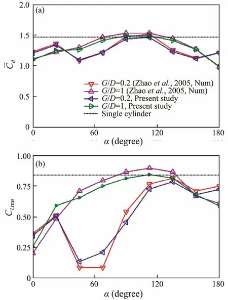
Fig.4 The force coefficients on the primary cylinder. (a)Mean drag coefficients; (b) RMS lift coefficients.
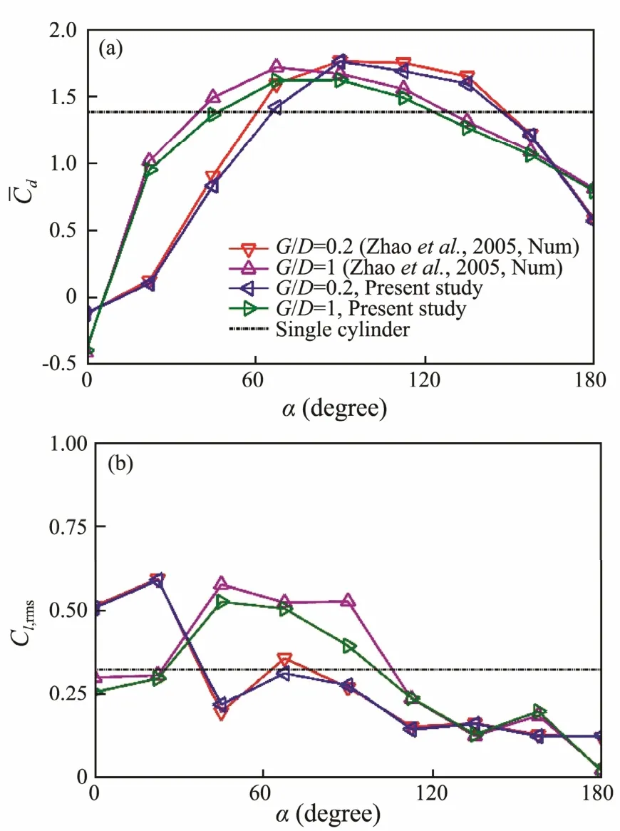
Fig.5 Force coefficients on the control rod. (a) Mean drag coefficients; (b) RMS lift coefficients.
5 Results and Discussion
5.1 The Effect of Control Rods on the Hydrodynamics of the Primary Cylinder
To compare the effects of differing arrangements of the control rods on the hydrodynamics of the primary cylinder, the results of the three modes (case 1, case 2 and case 3) are shown and discussed together.
To show the effect of the control rods on the hydrodynamics of the primary cylinder, the difference between the hydrodynamic forces on the primary cylinder and those on the single cylinder were defined as the suppression effect of the control rods. The relative difference based on the values of single cylinder are used, and some modification factors are defined as
Here, the superscript ‘d’ represents the difference between the corresponding values. The superscripts ‘m’ and‘b’ represent the hydrodynamic forces on the primary cylinder and the single cylinder, respectively.
Fig.6 shows the contours of on a configuration plane for different cases. In the region of G/D<0.1 &50˚<α<130˚, the drag coefficients of the primary cylinder in all these three cases increased markedly, which means that the effect of the staggered control rod on the drag coefficient was more pronounced than that of the tandem control rod. For other position configurations (G and α),the control rods can decrease the drag of the primary cylinder at different levels. In every case, the staggered control rod at a small or large enough angle could decrease the drag coefficient more effectively. As the gap ratio increased or the angle approached 90˚ (i.e., as the transverse distance between the primary cylinder and staggered control rod increased), the influence of the control rod on the drag coefficient of the primary cylinder became weaker. Comparing the effects of the control rods in these three cases, it can be found that the control rods in case 1 could most effectively decrease the drag coefficient, and the effect of control rods in case 3 was weakest among the three cases. It can be concluded that the tandem (either upstream or downstream) control rod in the combination was helpful in decreasing the drag coefficient, and the effect of the upstream tandem control rod was more obvious.
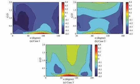
Fig.6 The effect of the control rods on the mean drag coefficient of the primary cylinder ().
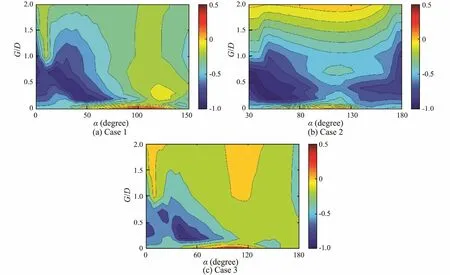
Fig.7 The effect of the control rods on the RMS lift coefficient of the primary cylinder ().
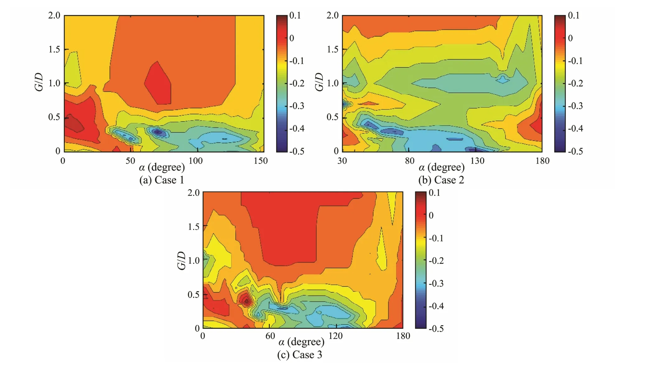
Fig.8 The effect of the control rods on the Strouhal number of the primary cylinder (Std).
The effect of the control rods on the Strouhal number of the primary cylinder is shown in Fig.8. In case 1 and case 3, the Strouhal number increased in most regions but decreased slightly in the region of G/D<0.5 & 60˚<α<140˚. In case 2, the Strouhal number decreased slightly in most regions. Comparing the Strouhal numbers in three cases, it can be concluded that the upstream tandem control rod in the combination slightly affects the frequency of the vortex shedding from the primary cylinder (so Figs.8(a) and 8(c) are similar). The downstream tandem control rod can largely change the effect of the staggered control rod on the Strouhal number of the primary cylinder (so Figs.8(b) and 8(c) are clearly different from each).
5.2 The Additional Effect of Double Control Rods
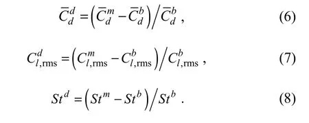
In subsection 5.1, the effects of the control rods with differing configurations on the hydrodynamic characteristics are discussed. However, thus far, the difference between the effects of the double control rods and the single control rods has not been investigated. Is the effect of the double control rods just a simple superposition of the effect of the single control rod? To discuss this issue, the additional effect is defined in this paper, which can be calculated as
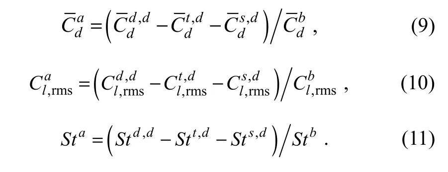
Here, the superscript ‘a’ represents the additional effect of the double control rods on the corresponding quantity.The superscript ‘d, d’ represents the effect of the double control rods on the hydrodynamic characteristics of the primary cylinder (case 1 or case 2), ‘t, d’ is the effect of the single tandem control rod, and ‘s, d’ is the effect of the single staggered control rod. If the quantity with superscript ‘a’ is positive, it means that the control rods combination has the additional effect of increasing the quantity, and if it is negative, the additional effect is to decrease the quantity.
Fig.9 shows the additional effect on the drag coefficient of the primary cylinder. In case 1, the additional effect decreases with increasing gap ratio and changes little with varying angles. The additional effect in the range of G/D>0.5 is negative, while it is positive in the range of G/D<0.5. In case 2, the additional effect clearly changes with varying gap ratio and angle. The additional effect is positive in most regions, but maybe slightly less than zero if the gap ratio is large enough (G/D>1). Comparing Figs.9(a) and (b), it can be found that the combination of upstream tandem control rod and staggered control rod is more suitable in reducing the drag coefficient on the primary cylinder, while the combination of the downstream tandem control rod and staggered control rod is unhelpful in reducing the drag coefficient.
Fig.10 shows the additional effect of the control rods on the RMS lift coefficient of the primary cylinder. In case 1, the absolute value of the additional effect was small and changed little with varying gap ratio and angle.In case 2, the additional effect is large in the region of 0.2< G/D < 0.5 & 30˚< α <120˚ and 0.9< G/D <1.4 & 30˚ < α <50˚, i.e., the combination of the downstream tandem control rod and the staggered control rod had the effect of increasing the RMS lift coefficient of the primary cylinder. For the other configuration in case 2, the additional effect of the control rods is not obvious. It can be concluded that the suppression effect of the two control rods in case 1 can be approximated as the simple superposition of the suppression effect of each control rod. However,the effect of two control rods in case 2 cannot be discussed using the mechanism of one control rod.
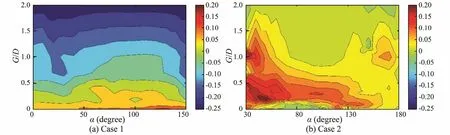
Fig.9 The additional effect on mean drag coefficient of the primary cylinder ().
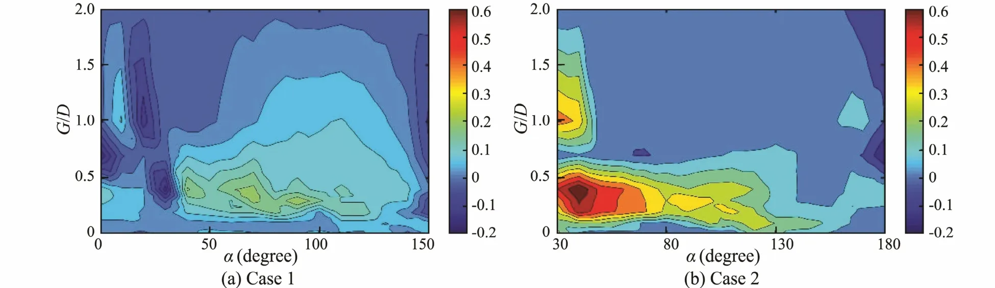
Fig.1 0 The additional effect on RMS lift coefficient of the primary cylinder
The additional effects of the control rods on the Strouhal number of the primary cylinder are shown in Fig.11.As G/D < 0.1, the additional effect is slightly larger than zero in case 1 and changes little with angle. In the range of 0.1< G/D < 0.5, the additional effect clearly changes with varying angles. As G/D < 0.5, the additional effect decreases with increasing gap ratio and changes little with angle. Despite the region of 0.3< G/D <1 & α < 80˚, the additional effect in case 2 can be negligible (nearly zero).In the region of 0.5< G/D <1 & α<40˚, the additional effect can significantly reduce the Strouhal number. In the regions of 0.7< G/D <1 & 35˚< α <60˚ and 0.2< G/D < 3 &45˚< α <55˚, the additional effect clearly increases the Strouhal number.
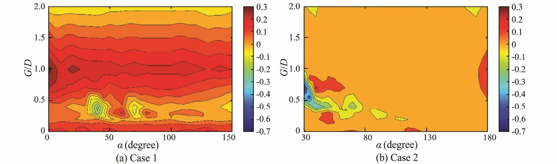
Fig.1 1 The additional effect on Strouhal number of the primary cylinder ( aSt).
5.3 Flow Structures Around the Cylinder System
To understand why the effect of the double control rods on the hydrodynamics of the primary cylinder is different from the single control rod, the flow structures around the cylinder system in different cases are shown and compared. As discussed in subsection 5.2, the additional effect of the double control rods was prominent at small angles. Therefore, the vortex contours at α=30˚ for G/D =0.1, 0.4 and 2 are shown and discussed in this section.
Fig.12 shows the vortex contours in case 1, and the vortex contours for a cylinder system with a corresponding single control rod are also included. It can be found that the vortex contours in third column are almost a simple combination of the vortex contours in first two columns. Therefore, the effect of the two control rods (upstream tandem control rod and the staggered control rod)on the vortex shedding from primary cylinder is just a linear superposition of the effect of the single corresponding control rod, which is the reason for the additional effect being small in case 1 as shown in Fig.10(a).
Fig.13 shows the vortex contours in case 2. As G/D =0.1, the downstream tandem control rod and the staggered control rod acted as one large downstream tandem structure, while the vortex contours in the third column were similar to those in first column, as shown in Fig.13(a).Therefore, the RMS lift of the primary cylinder in case 2 was close to the value of the primary cylinder with one downstream tandem control rod, i.e., the additional effect of these two control rods was weak. When G/D = 0.4, the flow structure in the second column was similar to that in third column. For the primary cylinder, the control rods in case 2 acted as a single staggered structure with a larger size than the control rod. Due to the downstream tandem control rod located around thestaggered control rod, the effect of the staggered control rod in confining the shear layer behind the primary cylinder was enhanced, and the influence of the formed vortex core on the primary cylinder was increased. Therefore, the additional effect of the control rods on the hydrodynamic characteristics of the primary cylinder is clear at G/D = 0.4 and α = 30˚, as shown in Fig.10(b). The effects of the downstream tandem control rod and staggered control rod on the vortex shedding from the primary cylinder were negligible, while the vortex contours behind the primary cylinder were similar in all three columns.
5.4 Hydrodynamic Characteristics of the Primary Cylinder
The variation of thehydrodynamic forces and Strouhal numbers with the angle of the staggered control rod at three typical spacing ratios (G/D = 0.1, 0.4 and 2) are analyzed in this section according to the distribution of the effect of the control rods.
Fig.14 shows the drag coefficients of the primary cylinder. As G/D = 0.1, the mean drag coefficients in case 1 were close to the values in case 2 and were smaller than those in case 3, which means that the tandem (either upstream or downstream) control rod can clearly reduce the drag coefficient in case 3 at such a small gap ratio. At G/D = 0.4, the mean drag coefficient was largest in case 3 and smallest in case 1. This means that the tandem (upstream and downstream) control rod can reduce the mean drag coefficient of the primary cylinder, and the effect of the downstream tandem control rod is more clearly apparent at such a moderate gap ratio. At G/D = 2, the effects of the downstream tandem control rod and staggered control rod were negligible, and the mean drag coefficients in case 2 almost equaled the values of case 3 at all angles.The upstream tandem control rod still affected the drag force on the primary cylinder. The drag coefficients were largely reduced in case 1, and the values change little with the angle.
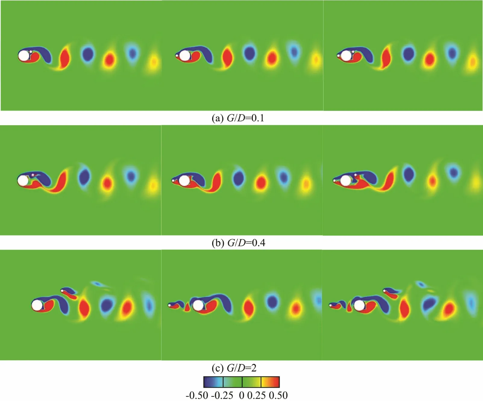
Fig.1 2 The vorticity contour near the cylinder system in case 1 at α = 30˚ (left and middle figures are the vorticity contours for the cylinder system with a corresponding single control rod; right figure is the vorticity contour for case 1).

Fig.1 3 The vorticity contour near the cylinder system in case 2 at α=30˚ (left and middle figures are the vorticity contours for the cylinder system with a corresponding single control rod; right figure is the vorticity contour for case 2).
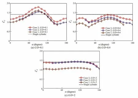
Fig.1 4 The mean drag coefficients of the primary cylinder.
The RMS lift coefficients of the primary cylinder at different gap ratios are shown in Fig.15. At G/D = 0.1, the RMS lift coefficients of the primary cylinder in case 1 and case 3 were almost equal at all angles, which means that the effect of the downstream tandem control rod on vortex shedding from the primary cylinder may have been negligible at such a small gap ratio. In case 2, the upstream tandem control rod could reduce the RMS lift coefficient slightly at any angle. At G/D=0.4, the RMS lift coefficients in three cases were approximated as α<40˚.As α>40˚, the RMS lift coefficients of case 1 were slightly smaller than those of case 3 and were much larger than those of the case 2. This means that the downstream tandem control rod can largely suppress the vortex shedding from the primary cylinder, while the effect of the upstream control rod on the vortex shedding from the primary cylinder is weak at such a moderate gap ratio. As G/D = 2, the RMS lift coefficients on the primary cylinders in case 2 and case 3 were almost equal at all angles,and were close to the value of the single cylinder. In case 1, the RMS lift coefficient was much less than the value of the single cylinder and changed little with varying angle. Therefore, only the upstream tandem control rod could affect the vortex shedding from the primary cylinder at such a large gap ratio. The effects of the downstream tandem control rod and staggered control rod were negligible.
Fig.16 shows the Strouhal numbers of the primary cylinder at different gap ratios. As G/D = 0.1, the Strouhal numbers in case 1 were similar to those in case 3 and slightly larger than those in case 2. As G/D = 0.4, the Strouhal numbers in different cases were different from each other in the range of 30˚<α<80˚. At other angles, the Strouhal numbers in all cases were approximately the same. At G/D = 2, the Strouhal numbers in case 2 and case 3 were close to the value of the single cylinder and were slightly larger than that in case 1 in the range of α<140˚.As α>140˚, the Strouhal number decreased with increasing angle.
Following the discussion above, some conclusions can be drawn. At small gap ratios (such as G/D = 0.1), the effect of the upstream tandem control rod on the primary cylinder can be negligible at any angle, and the hydrodynamic characteristics were only affected by the staggered control rod in case 1. However, the effect of the downstream tandem control rod is more remarkable than that of the staggered control rod and can reduce the force coefficients of the primary cylinder effectively at any angle. At moderate gap ratios (such as G/D = 0.4), the effect of the upstream tandem control rod on the primary cylinder increased with the spacing ratio, and the hydrodynamic forces were reduced at all angles by the upstream tandem control rod in case 1. The effect of the downstream tan-dem control rod in case 2 was, once again, not dominant.For small angles, the effect of the upstream tandem control rod was even larger than that of the downstream tandem control rod. As the gap ratio becomes large enough(such as G/D = 2), the effects of the downstream tandem control rod and the staggered control rod on the hydrodynamic characteristics of the primary cylinder are negligible, while the upstream tandem still influences the hydrodynamics of the primary cylinder and the effect decreases with increasing gap ratio.
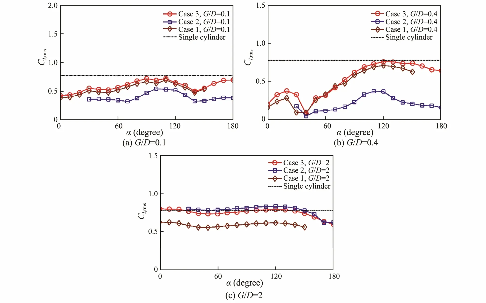
Fig.1 5 The RMS lift coefficients of the primary cylinder.

Fig.1 6 The Strouhal numbers of the primary cylinder.
5.5 Global Force Coefficient of the Cylinder System
In engineering practice, the global force of the cylinder system affects the dynamic behavior of the cylinder system directly. In this subsection, the variations of the global forces with the angle at G/D = 0.1, 0.4 and 2 are discussed. The global force coefficient of the system are calculated using the diameter of the primary cylinder,namely
Comparing Figs.14, 15 and 17, it can be found that the variation with angle of the force on the primary cylinder is similar to that of the global force, with the magnitude of the latter clearly being larger than that of the former. At all these gap ratios, the mean global drag coefficients in case 1 and case 3 were similar and larger than that in case 1. This means that the downstream tandem control rod has little effect on the mean global drag coefficient, while the upstream tandem control rod can reduce the mean global drag coefficient significantly. As G/D=0.1 and 0.4,the mean global drag coefficient was larger than that of the single cylinder as the angle approached 90˚. As G/D =2, the mean global drag coefficients in all cases was larger than that of the single cylinder as α<170˚, as shown in Fig.17(a).
Fig.17(b) shows the RMS global lift coefficients of the cylinder systems. As G/D = 0.1 and 0.4, the RMS global lift coefficients in case 1 and case 3 were similar and larger, respectively than that in case 2 at all angles. In all three cases, the RMS global lift coefficients were smaller than that of the single cylinder. As G/D = 2, the coefficients in case 2 were larger than that of the single cylinder at any angle. In case 1 and case 3, the coefficients were larger than that of the single cylinder in the range of α<30˚, while the coefficients were similar to that of the single cylinder at other angles.
Following the discussion above, it can be found that the control rods around the control rod will enlarge the mean global drag coefficient in most cases, and just reduce the mean global drag coefficient as the angle is small (α<40˚) or large (α>140˚) enough. As G/D = 0.1 and 0.4, the control rods can reduce the RMS global lift coefficient at any angle. As G/D = 2, the effects of the control rods on the coefficient in case 1 and case 3 were not obvious, while the control rods in case 2 could enlarge the coefficient significantly at any angle.

Fig.1 7 The global force coefficient of the cylinder system.
6 Conclusions
In this paper, the flow past the primary cylinder with one tandem (upstream or downstream) control rod and one staggered control rod at Reynolds number of 500 was simulated. The variations in the hydrodynamic forces and Strouhal numbers of the primary cylinder with spacing ratio and angle of the staggered control rod were analyzed.Following the above analysis, some conclusions can be drawn.
1) In the region of G/D<0.1 & 50˚<α<130˚, the effect of the staggered control rod is more pronounced than that of the tandem control rod, and the drag and lift coefficients on the primary cylinder are largely increased in all cases. For other position configurations (G and α), the control rods can decrease the hydrodynamic forces on the primary cylinder at different levels, and the effect of the control rods in case 2 is more obvious than in other cases.
2) The additional effect of the control rods in case 1 is weak at any configuration, and the influence of these two control rods on the hydrodynamics of the primary cylinder can be seen as a linear superposition of the effect of a corresponding single control rod. For the control rods in case 2, the additional effect is large in the region of 0.2<G/D <0.5 & 30˚<α<120˚ and 0.9< G/D <1.4 & 30˚<α <50˚.In this region, the combination of the downstream control rod and the staggered control rod is not conducive to sup-pressing the vortex shedding from the primary cylinder.
3) In cases where the upstream tandem control rod and the staggered control rod are located around the primary cylinder, the effect of the tandem control rod may be negligible at small spacing ratios (G/D=0.1). At modest spacing ratios (G/D = 0.4), the effect of the tandem control rod and the staggered control rod is comparable. At larger spacing ratios (G/D = 2), the effect of the upstream tandem control rod is prominent.
4) In cases where the downstream tandem control rod and the staggered control rod are located around the primary cylinder, the effect of the tandem control rod is prominent as G/D=0.1. The effect of the staggered control rod is weakened by the downstream tandem control rod. As G/D = 0.4, the effect of the staggered control rod exceeds that of the downstream control rod at small angles. As G/D=2, the effect of the control rods on the hydrodynamic characteristics may be negligible, and the primary cylinder acts as a single cylinder.
Acknowledgements
The authors are grateful to the support from the National Natural Science Foundation of China (Nos. 11372188, and 51490674) and the National Basic Research Program of China (973 Program) (No. 2015CB251203).
杂志排行

Journal of Ocean University of China的其它文章
- Effect of Different Dietary Protein and Lipid Levels on the Growth, Body Composition, and Intestinal Digestive Enzyme Activities of Juvenile Yellow Drum Nibea albiflora (Richardson)
- Establishing Gene Delivery Systems Based on Small-Sized Chitosan Nanoparticles
- Methylation Status of the Follistatin Gene at Different Development Stages of Japanese Flounder(Paralichthys olivaceus)
- Taxonomic Clarification of A Well-Known Pathogenic Scuticociliate, Miamiensis avidus Thompson &Moewus, 1964 (Ciliophora, Scuticociliatia)
- Structural Variation Analysis of Mutated Nannochloropsis oceanica Caused by Zeocin Through Genome Re-Sequencing
- A Comparative Study on Hydrodynamic Performance of Double Deflector Rectangular Cambered Otter Board