Deviation-Rectifying Control of Carbon Fiber Prepreg Slitting and Winding Machine
2018-07-11WenLiweiZhuTengfeiQinLihuaWangXianfengPanJieFengQiaoqiao
Wen Liwei,Zhu Tengfei,Qin Lihua,Wang Xianfeng,Pan Jie,Feng Qiaoqiao
1.College of Material Science and Technology,Nanjing University of Aeronautics and Astronautics,Nanjing 210016,P.R.China;2.Beijing Institute of Space Long March Vehicle,Beijing 100076,P.R.China
Abstract:With the growing needs of prepreg tapes for the automated fiber placement(AFP),the deviation-rectifying of prepreg in slitting process was investigated on a self-developed 16-tow prepreg slitting and winding machine.The process of slitting and rewinding of prepreg tape was introduced,and the reason of prepreg tape deviation in slitting process was analyzed.In order to ensure the quality of the narrow prepreg slits,the application of the fuzzy PID algorithm in a closed-loop control system was discussed.A fuzzy PID algorithm was designed by combining fuzzy rules and PID controller.By applying it to precise deviation-rectifying control strategy,the automatic control of rectification could be achieved with accuracy of 0.1 mm,which satisfies the requirement of the prepreg tape both in slitting quality and layup quality for AFP.
Key words:automated fiber placement;prepreg tape;slitting and winding;fuzzy PID;deviation rectifying
0 Introduction
Automated fiber placement(AFP)technology has become a heated research topic in the field of composite materials.The related researches include equipment study,manufacturing process study,and path planning and material study[1-3],etc.AFP employs narrow(3.18 mm,6.35 mm,12.7 mm in width)unidirectional pre-impregnated fiber as raw materials,with a specific combination of tow forming prepreg with variable width,which is placed onto the mold surface[4].It is a key technology of forming complex surface(such as fuselage,blended wing body,inlet,etc.),with a wide range of application,high molding efficiency and reliable part quality[5].The high quality,precision and reliability of AFP enable its application in the manufacture of structural components of large aircraft,launch vehicles and other types of aerospace vehicles in the developed countries[6-8].
At present,the preparation methods of prepreg used in AFP can be divided into two categories:Direct hot-melt method and slitting method.Direct hot-melt prepreg has lower efficiency,lower resin content and difficulty in width control,making it only suitable for small batch production for space grade prepreg.Slitting method slits prepreg directly with high efficiency and high precision,and it suits mass production,which is main method for AFP prepreg tapes[9].The principle of slitting mechanism is shown in Fig.1.AFP technology has high demands on the width and edge quality of prepreg slits,which can seriously affect the final fiber placement efficiency and product performance.This requires high slitting precision and quality of the slitting machines.Factors such as mechanical vibration and unsteady tension in the slitting process can lead to deviation of the prepreg,which affects the slitting precision and quality.Most of the traditional deviation-rectifying controllers use switch sensor,and its control method is applied to the traditional PID control[10-11].Traditional deviation-rectifying controller needs more sensors installed to ensure high rectification accuracy,and the PID control method has high precision,while the system has larger overshoot and overshoot time.In order to improve the slitting precision and meet the process requirements of prepreg,we propose a self-developed photoelectric deviation-rectifying control system based on fuzzy control algorithm,which can eventually realize the automatic rectification in the process of slitting[12-13].

Fig.1 Principle of slitting mechanism
1 Influence of Prepreg Tape Deviation on Slitting Quality
Due to the viscosity of prepreg,fiber residue and resin tend to stick on the blade,which will be detrimental to the quality of prepreg tows.As the prepreg is highly anisotropic,it is easy to be slit in the longitudinal direction but likely to crack in the transverse direction.The traditional slitting method without deviation control is unable to ensure the precision of tows.
Slitting method mainly contains three steps:unwinding,slitting,rewinding.In the slitting process for wide prepreg tapes,deviation often occurs,resulting in width change of the slit prepreg and material scrap.The width deviation of narrow prepreg tapes should be controlled within 0.1 mm after the slitting process,in order to meet the requirements of AFP.The so-called deviation refers to the non-straight movement of prepreg tape,where its centerline deviates away from the reference centerline,during slitting right after unwinding.
The wide prepreg is divided into 16 prepreg tapes by a circular cutter and is rewound by 16 groups of rewinding units,respectively.If the tensions on the 16 prepreg are not uniform,prepreg offset and significant separation will occur,resulting in uneven width of the prepreg taps.There are many reasons for prepreg tape deviation,such as the imperfect processed roller,installation inaccuracy,tension instability,irregular width and stretching of raw prepreg material and machine vibration.Prepreg tape cannot be slit with clear and precise borderline in the case of position deviation.
2 Construction of Automatic Deviation-Rectifying Control System
The self-developed photoelectric automatic deviation-rectifying control system is shown in Fig.2.The photoelectric sensor collects the position of the prepreg tape and feeds it back to the PLC controller.After fuzzy PID operation,pulses are sent to the driver to drive the stepper motor screw mechanism,controlling the movement of releasing roller and implementing rectification function.

Fig.2 Deviation-rectifying control system
The sensor is a U-shaped opposite-type photoelectric sensor with the analog voltage output,whose detection accuracy is up to 0.01 mm.The edge of the tape passes through the sensor,and the principle is shown in Fig.3.
When there is no obstruction between the lens,the prepreg is completely out of the sensor.At this time,the power value of received light is P.Within a certain emission circuit,P is a constant value.The power received by the receiver is P1=P/2(half of the light flux),when the prepreg is in normal position(Prepreg edge is located on the centerline of the lens).Therefore,an offset value of r can produce a unique output voltage value.

Fig.3 Principle of photoelectric detection
By experiment,the output voltage can be measured when the tape in Fig.3 is moving from left to right,and its relationship is shown in Fig.4.
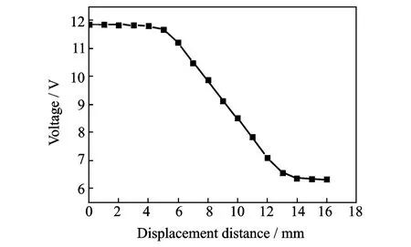
Fig.4 Output voltage linearity of photoelectric sensor
3 Automatic Deviation-Rectifying Control Scheme
The actual model of rectification system has many influencing factors and many variables which need to be compensated.Its construction parameter is not very clear,and it is a non-linear,time-varying and lagging system.A controller is required for good self-adaptation,which can automatically adjust the controlling parameters.By using a experience and knowledge based fuzzy PID control system,the mathematical model is object independent.It has some other advantages as well,for example,it overcomes the adverse effects to system performance,which are brought by the uncertainties of AC speed control system.
The fuzzy self-adaptive PID control system can detect and analyze the uncertain conditions,parameters,delay and interference in the control process.The on-the-fly self-tuning of PID parameters—KP,KIand KDcan be achieved by fuzzy reasoning.It is more advanced control system,which not only remains the simple principle,easiness and robustness of traditional PID control system,but also has better flexibility,adaptability and control precision.
In this paper,fuzzy PID control algorithm output linguistic variables are KP,KIand KDafter clarification by fuzzy control rules.And the input linguistic variable is the deviation of converted digital value from input voltage in photoelectric sensor after fuzzification,as shown in Fig.5.

Fig.5 Fuzzy PID control diagram
3.1 Fuzzy PID control scheme
3.1.1 Fuzzification of deviation,deviation change and output value
The inputs of the fuzzy controller are mainly measured.First of all,they need to be scale-converted to the values in discrete domains.This is actually a conversion of a domain of discourse into a certain number of small segments,which is quantifying each segment with a specific term,resulting in the formation of a discrete domain.After scaling,fuzzy sets are defined by assigning degree of membership to each specific term in the new discrete domain.In this example,the abso-lute deviation value|E|and the deviation changing rate|EC|are considered as input linguistic variables.Each linguistic variable takes three linguistic values:big(B),medium(M)and small(S),whose membership functions are selected as triangle functions[14],as shown in Figs.6,7.
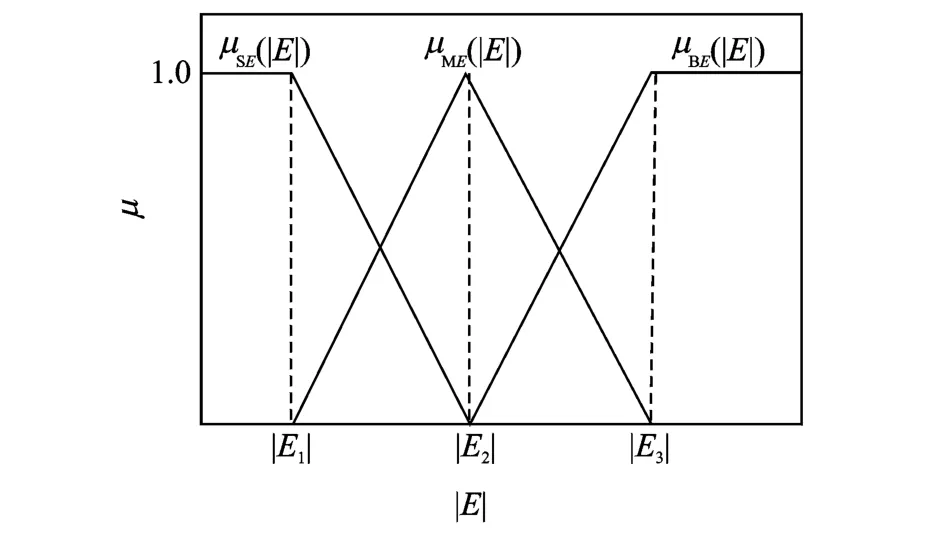
Fig.6 Membership functions of deviation|E|

Fig.7 Membership functions of deviation changing rate|EC|
Among them,the degree of membershipμ can be adjusted according to the actual situation of different turning points|E1|,|E2|,|E3|,|EC1|,|EC2|and|EC3|.By defining the membership function,numeric variables|E|and|EC|could be classified as“big medium or small”.In this example,the receiving end of the photoelectric sensor is a circle with a diameter of 15 mm.The detected analog voltage through the A/D module is converted into a digital value with resolution of 6 000.According to the experimental results,the relationship between digital value and deviation is shown in Fig.8.

Fig.8 Relationship between the number and the deviation
From Fig.7,it can be seen that when the distance is over 3.55 mm,the tape is located in the edge area of the sensor,or has been off the sensor,while the received digital variation range is very small.When the deviation is between 1.70 mm and 3.55 mm,the change of received digital value is very large.When the deviation is within 1.70 mm,the change of the received digital quantity tends to be moderate.
From the above analysis,|E1|is set as 0.15 mm,|E2|as 1.70 mm,and|E3|as 3.55 mm.In this example,an OMRON PLC type CP1 H-XA is selected as the processor,the program scan cycle is set as 100 millisecond,and the sampling period is also set to 0.1 s as well.In addition,|EC1|,|EC2|and|EC2|are set as 30,75,and 150,respectively.
Similarly,the required PID parameter values can be sorted out for different states by conventional method and fuzzification.And the membership functions are shown in Fig.9.
Degree of membership can be set by adjusting different turning points of the value—KP1,KP2,KI1,KI2and KD1,KD2,according to the actual situation.In this example,KP2,KP1are set to 0.5 and 1.5,respectively;KI1,KI2to 0.12 and 0.18,respectively;and KD1,KD2to 0.18 and 1,respectively.
3.1.2 Determination of fuzzy control rules
The setting of PID parameters must take into account the role of the three parameters at different stages and the relationship between them.From the traditional experience,it is known that the requirement of the parameters in the control process is as follows[15]:

Fig.9 Membership functions of KP,KI,KD
When the deviation|E|is large,larger KPand smaller KDshould be taken for better fasttracking performance of the system.At the same time,in order to avoid system response to a large overshoot,the integral action should be limited,and usually set as KI=0.
When the deviation|E|is in normal range,KPshould be set to small value,for system response to smaller overshoot.And in this case,the value of KIand KDshould be moderate,so as to ensure the system responding speed.And the value of KDhas a greater influence on the system response.
When the deviation|E|is small,KPand KIshould be larger,for better system stability.At the same time,to avoid the oscillation of the system around the setting value,and for the antiinter-ference performance of the system,when|EC|is small,the KDvalue should be large,and usually taken as medium value;when|EC|is large,KDshould be small.
According to the above rules,the fuzzy control rules are set as shown in Tables 1—3.

Table 1 KPfuzzy control rules

Table 2 KIfuzzy control rules

Table 3 KDfuzzy control rules
3.1.3 Fuzzy reasoning and clarification(defuzzification)
According to Eq.(1),the weighted average method(gravity center method)is used to calculate the product of the elements,their degrees of membership and the ratio of the elements for each state.That is,the fuzzy output of each state should be clarified[16].

where j can be small“S”,medium “M”and big“B”,in the three states.According to the membership function of KPand the equation,KPvalue for each state can be obtained

According to the aforementioned fuzzy rules,input deviation|E|and deviation change rate|EC|can be obtained by inference corresponding to the output.Firstly,the membership degree of the corresponding output is obtained,for example,when both input variables|E|and|EC|belong to categary “S”,according to fuzzy reasoning algorithm,output KPwill belong to“B”.And the corresponding membership degree is

where the operator“∧”takes the minimum value of both of the corresponding values,namely

In this case,obtained is the membership degree of output KPadjusted according to fuzzy rule,under different|E|and|EC|variables.A numerical example to validate the fuzzy rule is given as follows:|E|is assumed as 1.5 mm and|EC|as 40.Then,the membership degree of|E|is 0.13 at“S”state,0.88 at“M”state and 0 at“B”state according to Fig.5.And the membership degree of|EC|is 0.8 at“S”state,0.2 at“M”state,0 at“B”state.According to Table 1,it can be known that there are nine kinds of output states,respectively


According to Eq.(2),the weighted average of these states can be calculated by the corresponding P,I,D parameter values

One can know that when the deviation is 1.5 mm and the variation rate of deviation is 40,the output KPis 1.23,following the fuzzy control rule.
Similarly,PID parameters KP,KI,KDobtained by fuzzy reasoning,can be transferred directly into the PID instruction of PLC and the output control u can be calculated according to the following equation

3.2 Output control scheme
The drive system employs a stepper motor to drive the screw movement,with a controller of OMRON CP1H-XA PLC.For the photoelectric sensor voltage signal reading,input analog range is 0—10 V,and A/D resolution is set to 6 000.For stepper motor control,“pulse+direction”mode is used,and the independent mode is applied for motor control.
4 Experimental Results
In this case,the deviation-rectifying device is mounted on the unwinding roller and the deviation-rectifying takes place before slitting.Since a set of circular blades are fixed,the widths of prepreg tape between each two blades remain constant.Therefore,first of all,the deviation-rectif-ying should be turn on to slit at a speed of 16 m/min,after the centerline is aligned,as shown in Fig.10.Large width of the remaining material will affect the measurement.Therefore,a scrap strip of prepreg at the edge is selected as a research object.Measured at 10 s interval,the width variation is studied,comparing with the scrap strip of prepreg after slitting without the rectifying device.And the rectifying effect is characterized according to the straightness of prepreg.Wide prepreg tape slitting experiment is shown as Fig.11.

Fig.10 Slitting process of wide prepreg tape

Fig.11 Wide prepreg tape slitting
The relationship between the width of edge scrap strip at the rear edge and the slitting time with installation of rectifying device is shown in Fig.12.The relationship between the width of edge scrap strip at the rear edge and the slitting time with isolation of rectifying device is shown in Fig.13.
As can be seen from Fig.12,although the centerline is aligned before slitting,prepreg tape deviation occurs at the beginning stage,due to rotation of the slitting roller axis,machine vibration,inconsistencies of uncut prepreg tape width

Fig.12 Results of the post deviation

Fig.13 Results of separation of the isolated deviationrectifying device
and other reasons.The width deviation of the edge scrap strip prepreg tends to be stable after 30 s,and maintains at the vicinity of 4.76 mm.
As can be seen from Fig.13,the width of the edge scrap deviated drastically after 20 s with isolation of the rectifying device.During the period of measuring,the width is not stable and deviates largely.This results in unexpected inconsistency of tape width,which has negative impact on the next subsequent slitting process.
5 Conclusions
(1)The slitting technology of prepreg narrow tapes for the AFP is discussed.Reasons of prepreg tape deviation in slitting process is analyzed,automatic deviation control system is set up for better precision.
(2)A self-developed carbon fiber prepreg slitting-winding machine is integrated with photo-electric rectifying control system.Unlike the traditional rectification control,fuzzy PID control algorithm is applied to the rectifying control of prepreg slitting-winding machine,achieving a good rectification effect.Deviation-rectifying accuracy reaches 0.1 mm.
Acknowledgements
This work was financially supported by the National Basic Research Program of China(973 Program),the Priority Academic Program Development of Jiangsu Higher Education Institutions,and the Fundamental Research Funds for the Central Universities(No.3082615NS2015056).
杂志排行

Transactions of Nanjing University of Aeronautics and Astronautics的其它文章
- Arnoldi Projection Fractional Tikhonov for Large Scale Ill-Posed Problems
- SEM-Based Method for Performance Evaluation of Wired LANs
- High-Order Discontinuous Galerkin Solution of Compressible Flows with a Hybrid Lattice Boltzmann Flux
- Experiment on a Double-Foot Stepping Piezoelectric Linear Motor
- Structural and Piezoelectric Properties of Sr0.6Ba0.4Nb2O6Micro-rods Synthesized by Molten-Salt Method
- A Real-Valued 2D DOA Estimation Algorithm of Noncircular Signal via Euler Transformation and Rotational Invariance Property