Global Tool Path Fairing Algorithm for Automated Fiber Placement
2018-07-11WangXianfengYeZihengWangRuozhouZhaoCong
Wang Xianfeng,Ye Ziheng,Wang Ruozhou,Zhao Cong
R&D Center for Composites Industry Automation,Nanjing University of Aeronautics and Astronautics,Nanjing 210016,P.R.China
Abstract:A global energy fairing method,applied to automated fiber placement(AFP)tool path,was proposed.The main purpose was to improve the adaptability of AFP path towards part with sharp curvature variation as well as product quality.The relation between path geometric property and manufacturing property was discussed and a series of experiments were carried out.Based on cubic B-Spline global fairing method,the AFP tool path was faired which decreased the tool path curvature and curvature changing rate.Compared with initial ones,the path faired by the proposed method was relatively flat and smooth,which contributed to layup efficiency and reducing bulking defects.The method was demonstrated potentials in application for AFP manufacturing,especially for aeronautic and aerospace industry practice.
Key words:automated fiber placement(AFP);tool path fairing;fiber steering;manufacturing
0 Introduction
In recent years,carbon fiber reinforced plastic(CFRP)has wide applications in fields of aeronautics and astronautics.Compared with aluminum alloy,CFRP parts are able to stand equal load with relative lower density,which decreases the whole weight[1-2].Among several composite manufacturing technologies,automated fiber placement(AFP)and automated tape laying(ATL)have been increasingly applicated in various fields.Automation and high efficiency are the main advantages over traditional techniques.
The essential difference between AFP and ATL is the width of the prepreg.In general,AFP uses narrow tows(1/8″to 1/2″)while ATL uses large scale tape(up to 300 mm).Thus,according to prepreg width,ATL is capable of processing part of small curvature or plate in high efficiency while complex parts with sharp curvature variation are the option of AFP[3].AFP and ATL both place prepreg on the mould surface to generate a part.During the placement process,an elastic roll is used to press the heated prepreg on the mould surface to make the ply compact.Based on the designed placement angle,tool path is generated to guide end-effector to conduct placement process,which requires the surface covered without gap or overlap between adjacent tapes or groups of tows[4].In terms of AFP,it places various tows simultaneously and each tow is driven individually and can be clamped,cut,and restarted during manufacturing.This makes it possible to deliver each tow at individual speed,enabling some tow steerings to fit various path design.However,fiber steer causes manufacturing defects and it results from the material property.According to fiber steer,part is produced in optimal mechanics design but the defects such as buckling and bridging would damage the product quality[5].
CAD/CAM software technology is crucial to AFP,and it computes accurate tool path and is transfered into NC code for manufacturing.Besides proposing new tool path generating method,post-process of already computed tool path is another research emphasis[6-7].
Based on an already computed path,postfairing method is able to optimize the current path.Fleisig et al.[8]fitted 5-axis tool path in three B-spline,which focused on the reduction of processing time.Ho et al.[9]proposed a quaternion method to smooth the tool orientation under permitted error range.Taking advantage of the degree of tool machine redundancy,Piece et al.[10]improved the AFP tool kinematic behavior and decreased the processing time.Above all,the studies on tool path smoothing mainly concentrate on reducing processing time and improving tool kinematic behavior,while tool path position fairing in AFP is not mentioned.Layup quality is sensitive to path curvature because of the material inherent property.When the geodesic curvature of tool path reaches its critical value,bulking defect takes place and it may lead to part quality decrease or even placement failure.We propose a post-fairing approach that dedicates to improve AFP path smoothness for better product quality.
1 AFP Tool Path Analysis
1.1 Placement steering analysis
Prepreg typically consists of reinforcement fiber and resin matrix.It is expected that prepreg tows are placed onto the mold with winkle.However,in case of large curvature part,it is inevitable to produce defects,e.g.buckling.The detailed analysis is as follows:

As shown in Fig.1,the curvature k of surface curve can be decomposed into knand kg,which represent the direction of n(which is the surface normal)and u(which is normal to n and the tangent t),respectively.It is illustrated as:u=t×n.Then,curvature k is decomposed as Tool path in AFP represents the central line of tows.n and u represent the thickness direction and the width direction of prepreg,respectively.According to the bent beam theory,in case of width far greater than thickness,equal curvature causes larger strain in width direction than thickness,which may lead to buckling defect[11].
Select infinitesimal element ABCD(Fig.2)as target object.Let AB and DC be perpendicular to fibers and extend them to intersect at O,with prepreg width as w and the included angle between AB and CD as dα.Let ABCD be tangent plane,and AD and BC as arc.It is concluded that

Fig.1 Frame coordinate of surface curve

Fig.2 Principle of fiber steering during AFP process

It is obvious that arc length of AD is larger than that of BC.
Generally speaking,fibers are prone to buckling under compressing stress to release the load.As shown in Fig.2(b),AD displays tensile strain under tension while BC is under compression.Then BC inclines to buckling and the phenomenon of structure instability may occur.The defect alters the fiber structure and the prepreg no longer maintains the initial mechanical property.Let AD be under no deformation and BC under compressing stress.The compressing strain is illustrated as follows

It is shown thatεis relative to kgand w.Strainεincreases with the increase of kg,and whenεreaches the critical value,buckling takes place.According to fiber buckling model,it is vital to keep AFP path curvature in a relative low standard for the sake of processing quality[12].
1.2 Layup quality analysis of AFP tool path
Current path is able to fit variable parts with mild curvature variation,cylinder,for instance.However,it is a remaining problem that the applicability towards complex part is not satisfied,which mainly embodied in the fiber defects.In these situations,path computed in fixed-angle method has a large curvature variation.It increases the chance of fiber defects and damages the part quality.
For instance,as shown in Fig.3,a typical aircraft S-inlet has special geometric features.Specifically,it consists of a steep convex with large curvature and a corresponding concave.The shape of S-inlet involved in this paper is very complicated.Because one end cross section of S-inlet is circular,but the other one is rectangular.And the curvature along the central axis direction has great variation.Another feature is the transitional peak-like edge that link adjacent surfaces,which is the area of sharp geometric change as well.Different manufacturing defects take place during fixed-angle placement.As shown in Fig.4,buckling defects normally appear at the area of the edge,simply because of the sharp path curvature standard.On the other hand,fiber bridging occurs in concave area resulting from the tensile force during process.

Fig.4 Buckling defects in S-inlet AFP manufacturing
2 Overall Methodology of Global Energy Smoothing Method
2.1 Principles of smoothing
There are two main aspects of curve fairing research:(1)The study of basic fairing principle,which mainly focuses on determining what sort of curve is smooth;(2)fairing algorithms,which are based on a serious of mathematic treatment.During the fairing method,fairing principle determines the mathematic principle as well as the function of algorithms.The general smooth principle is still not certain;however,four common principles are concluded as follows:(1)The curve is C2continuous;(2)the curve has no redundant inflection points;(3)the curvature changing rate of the curve is even;(4)the curve has small strain energy[13-15].
In general,fairing method have two main method:Global and local fairing method.Energy method,least square method and wavelet method are typical methods of global fairing,of which energy method is widely adopted.The main function of energy method is to decrease the strain energy of target curve under appropriate constrains[15-17].Curve faired by traditional energy method is tend to approach a straight line if without limit,which has the lowest energy level.The process decreases the global strain energy as well as global curve curvature.Yet the curvature variation changing rate is not considered.The phenomenon of shape curvature transforming exists and it ignores Principle(4).Besides,the tangential including angle between adjacent data points is also relative to curvature.The continuous tangential vector guarantees the smooth orientation transform.And once the included angle is too large,the path may not be smooth and the rotation axis of processing end-effector could rotate sharply,which damage the manufacturing efficiency as well as the fiber orientation.
2.2 Mathematic model of global fairing method
Let a cubic B-spline curve interpolate with the given path data points{Qi0}(i=0,1,2,…,n)

where{bj0}is the control vertexes and{t}(t=0,1,…,n+6)the node vectors.The data parameterization is accomplished by the method of arc length accumulation

where lj=|Qj-1Qj|is the arc length.The target function is defined as

The second derivative of Eq.(7)is

where{bj}is the control vertexes of the faired curve.
Regardless of stiffness coefficient,the strain energy E of P(t)(0≪t≪1)is defined as the arc integral of curvature k squared

Traditional energy method intends to achieve the minimization of Eq.(9)under the limit range.Yet the minimum of E cannot ensure the curvature changing rate is small as well.In order to even the curvature variation,another coefficient D is introduced

where kirepresents the relative curvature at Pi=P(ti+3).It is notable that,when direaches 0,ki-1,kiand ki+1vary linearly with the arc length.And the curvature variation around Pidecreases with the value of di.In conclusion,the coefficient D reflects the curvature changing rate of target curve and the new objective function is defined as follows
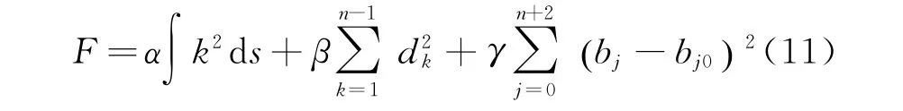
whereα,β,γare given constants greater than 0.The smaller of F,the smoother the target curve.Thus,the main task is to achieve the minimum of F under constraintHowever,the minimum solution is a nonlinear problem and it is hard to obtain the exact solution.To simplify the solving progress,Eq.(11)is transformed into linear equations.Replace curvature k with the second derivatives P″(t)and d t with d s


In Eq.(12),{bi}(i=0,1,…,n+2)is the only unknown quantity.

Eq.(14)is a set of linear equations of{bj}.Set b=(b0,b1,…,bn+2)Tand Eq.(14)can be expressed in matrix form

where A={aij}is the coefficient matrix

Vector c=(c0,c1,…,cn+2)Tis defined as follows

It is not hard to verify that coefficient matrix A is a symmetric matrix.And once|i-j|>4,set aij=0,which illustrate that the semi-band width of A is 5.Furthermore,whenαandβare far less thanγ,A is a symmetric positive definite matrix and it ensure the existence of unique solution to Eq.(15).Above all,the optimized control vertex{bj}can be obtained by solving Eq.(15).
Algorithm procedure
The fairing algorithm process is accomplished by VC++6.0 and Matlab R2014a.The process is composed of the following steps,as shown in Fig.5.
(1)Input the target tool path.
(2)Based on cubic B-spline,interpolate the data points{Qi0}.The whole process mainly includes vector parameterization and the calculation of control vertex{bi0}.
(3)Input the parameterα,β,γ,ε,and compute the faired control vertex{bi}through the global energy method.
(4)Obtain the optimized data points{Qi}and determine the deviation from the original location d=|Qi-Qi0|.Once d is larger than(or less than)ε,setand return to the beginning of Step(4).
(5)Output the optimized path if deviation is under the permitted range.
The fairing function can be shaped by adjusting the parameters.Generally,the value ofα should be within a certain range,otherwise the phenomenon of non-convergence will occur during the iteration process.With a smallerβ,the curve deviation is smaller but the smooth effect is worse;with a largerβ,the smoothness of target curve is better but the deviation is larger.

Fig.5 Algorithm steps of global path faring for AFP
3 Experiment
The global energy method is applied to AFP tool path,especially for complex part with sharp curvature variation.The test part is a simplified aircraft S-inlet with a 900 mm width and a 1 660 mm length approximately.The mould is meshed into STL(STereo lithography)and the test path is generated in fixed-angle method.Prepreg used in this experiment is X850 produced by CYTEC,with a tow width of 6.35 mm,and the minimum curvature radius has been proved to be R 1 000 mm.Setα=10-7,β=10-7,γ=1 and the maximum deviationε=1 mm.The detailed analysis is as follows.

Fig.6 Deviation of initial path after global faring treatment
Fig.6 shows that the deviation is controlled under the given value,which demonstrates the deviation of the optimized path can be regulated precisely.The curvature compairson between the initial and the smoothed curve is presented in Fig.7(a).It is obvious that the global curve curvature has a sharpe decrease and the change rate is also been controlled.Besides,the tangential included angle between adjacent data points is also been faired,as shown in Fig.7(b).Both curvature and tangential included angle have a significent decrease especially in peak value.Fig.8 shows the curvature change rate between initial and faired path,and the result is obvious that the curvature changing range has been decreased.

Fig.7 Curvature and tangential included angle comparison between initial and optimized paths
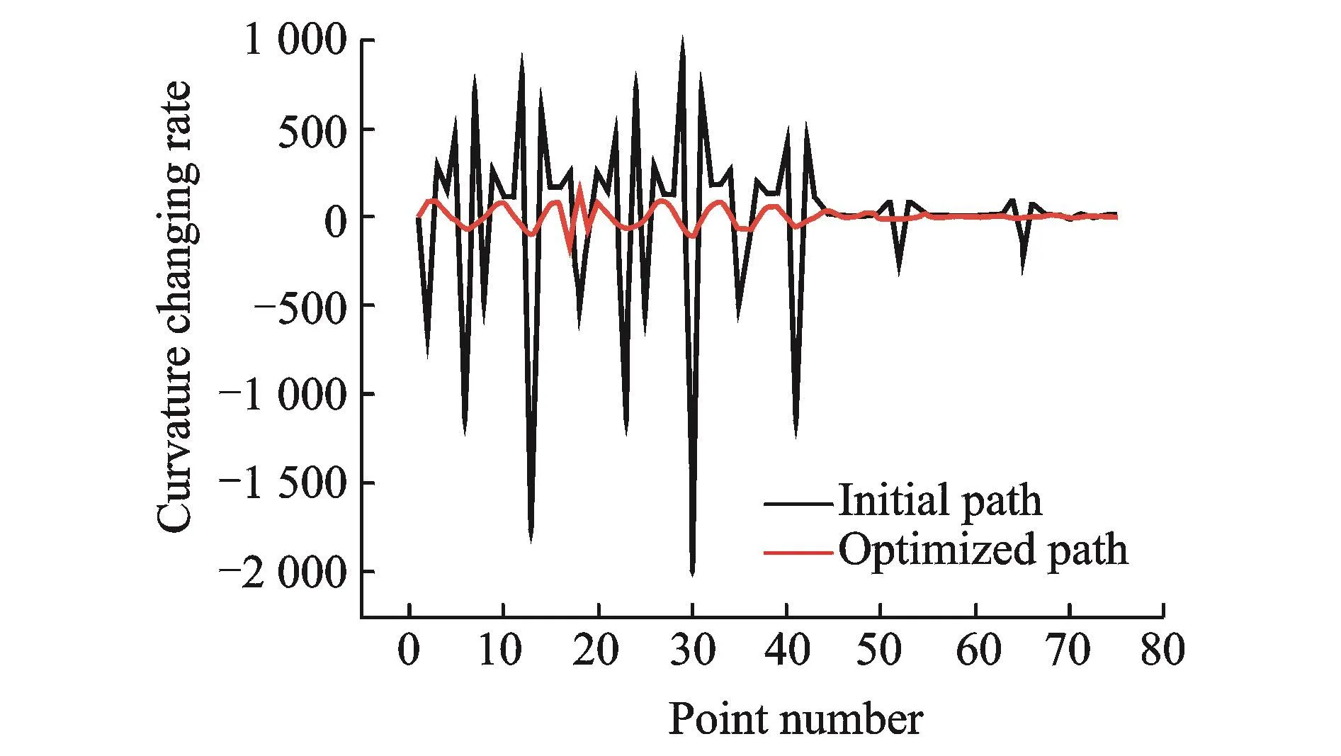
Fig.8 Curvature change rate comparison between initial and optimized paths
The practical placement experiment has been carried out with the AFP equipment designed by NUAA.The focus is the area that has large curvature variation which is the peak-like edge and Figs.9(a)and(b)show the fiber situation at the edge area of initial and faired path,respectively.It is obvious that the fixed-angle path has buckling defect and the deformation degree has been decreased after fairing treatment.

Fig.9 Practical AFP manufacturing comparison
4 Conclusions
Based on B-spline fairing theory,a global faring method that applied in AFP tool path was presented.Considering the manufacturing process,the algorithm intended to decrease curvature of a complete path and to control the curvature change rate.The main principle of the algorithm was to decrease the global strain energy and to smooth the curvature variation rate.Four parametersα,β,γandεwere introduced to regulate the fairing function.α,β,γwere relative to the global curve curvature standard,the curvature change rate,the deviation of initial data points,respectively.Andεrepresented the maximum deviation,which could be adjusted to fit the practical requirement.It was analyzed that the method suceeded in decreasing the path curvature and curvature change rate.Moreover,the tangential angle between adjacent data points was also smoothed,which is relative to fiber steering and manufacturing efficiency.Practical placement experiment had been carried out and the result validated the feasibility of global faring method.
Acknowledgements
This work was supported by the Major Science and Technology Projects of China(No.2016ZX04002-001-07)and Basic Scientific Research Fund(56XAA15057).
杂志排行

Transactions of Nanjing University of Aeronautics and Astronautics的其它文章
- Arnoldi Projection Fractional Tikhonov for Large Scale Ill-Posed Problems
- SEM-Based Method for Performance Evaluation of Wired LANs
- High-Order Discontinuous Galerkin Solution of Compressible Flows with a Hybrid Lattice Boltzmann Flux
- Experiment on a Double-Foot Stepping Piezoelectric Linear Motor
- Structural and Piezoelectric Properties of Sr0.6Ba0.4Nb2O6Micro-rods Synthesized by Molten-Salt Method
- A Real-Valued 2D DOA Estimation Algorithm of Noncircular Signal via Euler Transformation and Rotational Invariance Property