Analysis of the vortices in the inner flow of reversible pump turbine with the new omega vortex identification method *
2018-07-06YuningZhang张宇宁KaihuaLiu刘凯华JinweiLi李金伟HaizhenXian冼海珍XiaozeDu杜小泽
Yu-ning Zhang (张宇宁), Kai-hua Liu , (刘凯华), Jin-wei Li (李金伟), Hai-zhen Xian (冼海珍),Xiao-ze Du (杜小泽)
1. Key Laboratory of Fluid and Power Machinery, Ministry of Education, Xihua University, Chengdu 610039,China
2. Key Laboratory of Condition Monitoring and Control for Power Plant Equipment (Ministry of Education),North China Electric Power University, Beijing 102206, China
3. Beijing South-to-North Water Diversion Tuancheng Lake Management Office, Beijing 100195, China
4. China Institute of Water Resources and Hydropower Research, Beijing 100048, China
Introduction
As an essential component of the pumped hydro energy storage power plants, the reversible pump turbine plays an important role in the stability of the electrical systems through its ability of quickly meeting the electricity demand of the system and maintaining the frequency and the voltage of the system[1-3]. The aforementioned features of the reversible pump turbine are very important for the grid system with high penetration levels of the renewable energies (e.g., the wind energy[4]). The reversible pump turbine could be operated both in the turbine mode and in the pump mode with frequent shifts between different operational modes to satisfy the demand of the system. As a result, many instability problems (e.g., the strong pressure fluctuation[5-6], the hysteresis[7-8], the cavitation[9], the vibration and crack[10-12]and the rotating stall[13-14]) may occur,especially when the reversible pump turbine works under the off-design conditions. The formation of the vortex is one of the essential elements in the instability problems of the reversible pump turbine.The generation of vortices often accompanies with complex fluid flow phenomena inside the turbine (e.g.,the cavitation, the flow separation, and the rotating stall). When the undesirable flows are fully developed,a strong pressure fluctuation will be generated, and transmitted to the upstream (e.g., the vaneless space)to form more vortex structures locally. More details of the instability of the reversible pump turbines can be found in our recent review[1]. Hence, to solve the instability problems of the reversible pump turbine, it is necessary to better understand the associated vortex structure.
Numerous algorithms and their applications of vortex identification methods are reviewed in another of our paper[15], including applications in the pressure wave propagation[16-17], and the cavitating flow[18].Generally, the vorticity magnitude method is usually employed to identify the vortex in the turbulent flow.In some special regions (e.g., the flow in the laminar boundary layer near the wall), this method sometimes gives some incorrect identifications of the vortices.The2λ[19]andQ[20]criterions are also widely employed during the vortex analysis of the hydroturbines, but their results highly depend on the selections of the related critical values. With large values of the related parameters, weak vortices might be ignored,while with small values, some vortex structures can not be distinguished. In order to have a good balance,Liu et al.[21]proposed a new omega method to identify the vortex through defining a ratio between the vortical vorticity and the total vorticity (denoted asR), which corresponds to the cases with the vorticity overtaking the deformation. In the above method, the selection of a fixed threshold is shown to be suitable for many demonstrating cases and both the strong and weak vortices could be captured at the same time. Liu et al.[21]has validated the new method by applying it to the vortex identification of the complex fluid flow e.g., the boundary layer transition, the micro wave generator, and the roughness induced transition. The traditional methods (e.g.,2λ criterion andQcriterion) were also compared to demonstrate the superiority of the new omega method. Some further developments of this method can be found in Liu et al.[22], Dong et al.[23].
The vortices in the reversible pump turbines are complicated and varied in different operational modes.A large number of investigations show that the vortices may block the flow channels, generating a significant pressure fluctuation when the pump turbine works in the turbine brake and runaway modes. Hence,a well-defined method (e.g., the new omega method here) is required for the vortex identification in the reversible pump turbines.
1. Methods for vortex identification
The new omega method will be briefly introduced based on Liu et al.[21]. Liu et al.[21]divided the vorticity into two parts: one for the rotation of flow is called the vortical vorticity, the other is called the non-vortical vorticity. The ratio between the vortical vorticity and the whole vorticity is used to define the vortex. According to Liu et al.[21], in the fluid, the vorticity and the deformation exist at the same time.Hence, the vortex is formed when the vorticity prevails over the deformation. Then, the required ratio could be calculated using the vorticity and the deformation tensors defined by the velocity gradient.
The related equation can be described as follows[21]:
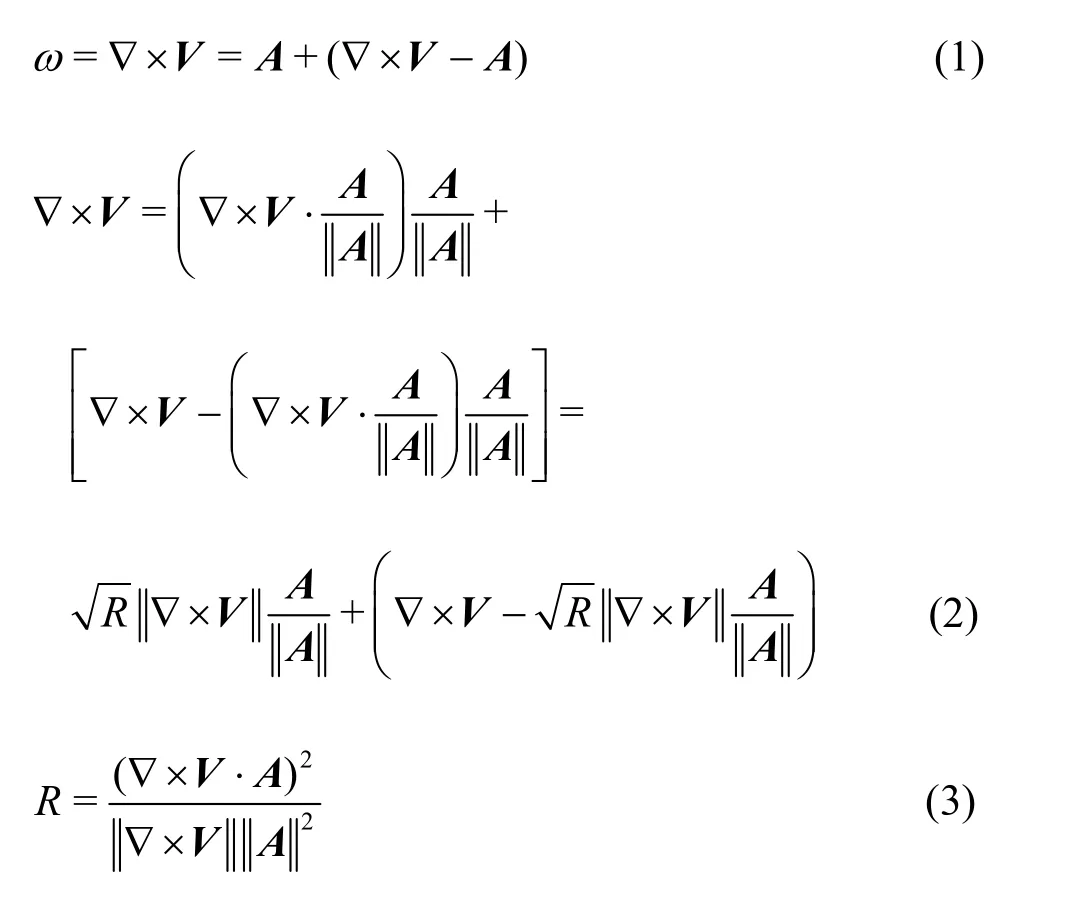
where ω is the total vorticity, A is the vortical vorticity,Ris the ratio between the vortical vorticity and the total vorticity, the symbol denotes the norm operation. The second term in Eq. (1)represents the non-vortical vorticity. A and ω have different directions in most cases. According to Eq. (3),Rvaries within the range of [0,1]. =0Rrepresents the pure deformation and =1Rrepresents the pure rotation. In our model, the geometry of the reversible pump turbine model is three dimensional and the flow is a turbulent flow.
In order to calculate thethreshold ofRin a complex flow, the velocity gradient can be decomposed as follows[21]:
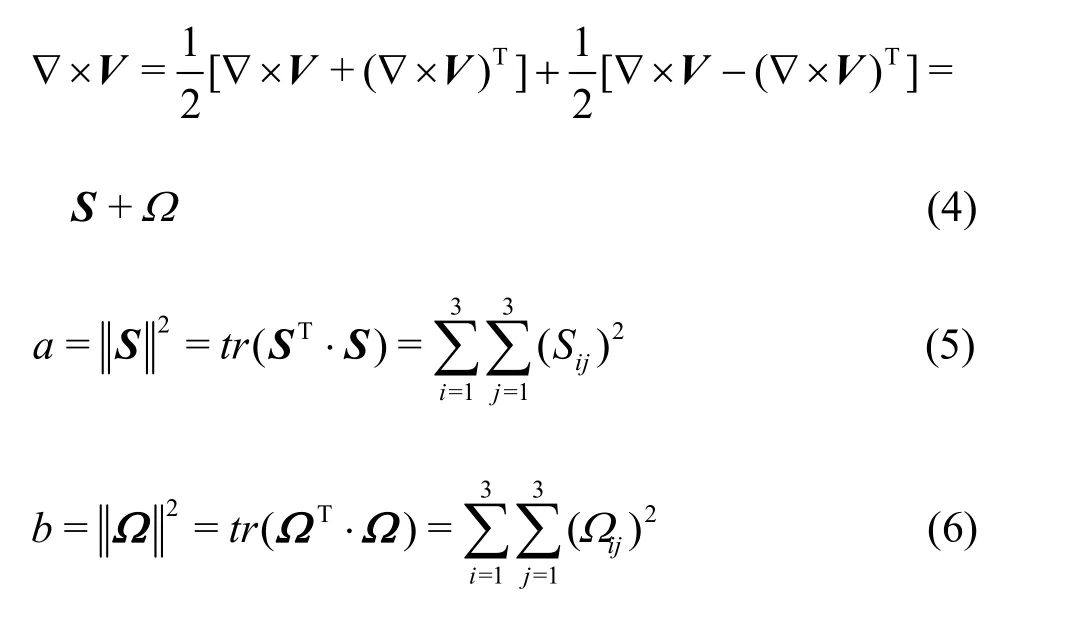
where S is the deformation tensor, Ω is the
vorticity tensor,trrepresents the trace of the matrix,aandbare the squares of the norms of S and Ω , respectively. Then,Rcould be defined as

where ε is a positive infinitesimal number, which is employed to avoid the case with a dividend of zero.Generally speaking, the value of ε depends on the geometry and the velocity parameters of the object. In this paper, the nominal diameter of the impeller of the model reversible pump turbine is 0.24 m and the maximum flow rate is tens of meters per second.Hence ε = 10-6is selected in the present study. Liu et al.[21]verified that the omega method is not sensitive to theRvalue in a certain range (0.51-0.60) when it is used to identify the vortex in the flow. WhenR= 0.52, the distinct vortex structures are identified in many different cases. Therefore, the uniform valueR= 0.52 is employed to identify the internal vortices of the reversible pump turbine in different operational modes.
2. Basics of numerical simulations
The numerical simulation is based on solving the turbulence flow of the whole passage of the model type reversible pump turbine in a large pumped hydro energy storage power plant. The main geometrical and operational parameters of the unit are shown in Table 1. The simulation settings are listed in Table 2. During the simulation, a uniform boundary condition is posed at the inlet of the spiral casing and the upstream disturbance is ignored[24].

Table 1 Parameters of the model type reversible pump turbine
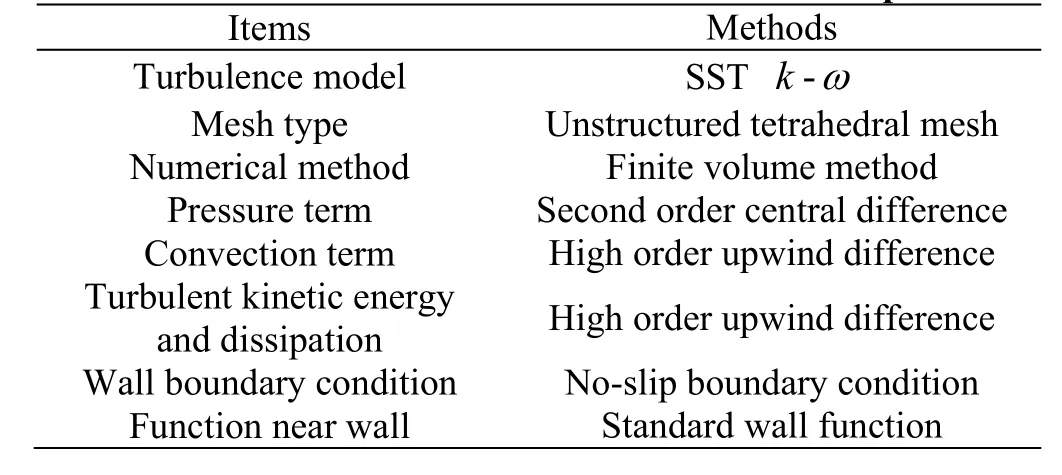
Table 2 Methods for numerical simulation and setups
The reversible pump turbine is the key unit in the pumped hydro energy storage power plant. The main components of the reversible pump turbine are shown in Fig. 1, including the spiral casing (the translucent body in green color), the stay vanes (in red color), the guide vanes (in blue color), the impeller (the translucent body in purple color), and the draft tube (in orange color). In order to satisfy the varied demands,the reversible pump turbine is designed to be able to work in a variety of operational modes. Figure 2 shows the discharge-speed characteristic curve of the pump turbine in the generating mode. The discharge and speed factors (denoted asednandedQ, respectively) are defined by Eqs. (8), (9) according to the IEC 60193 standards.
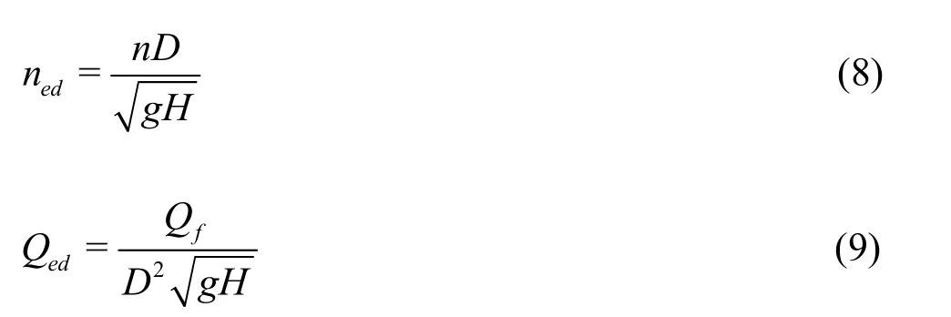
whereHis the water head,Dis the diameter of the impeller,nis the rotational speed of the impeller,Qfis the discharge of the turbine. When the pump turbine works in the generating mode, these parameters are defined as taking positive values.
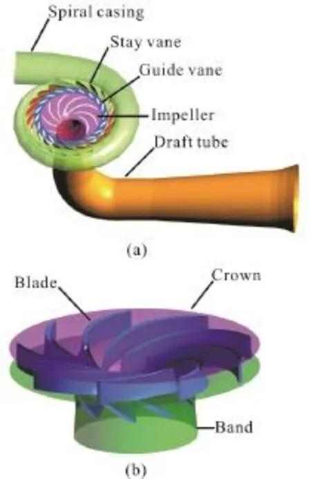
Fig. 1 (Color online) The main components of the reversible pump turbine including the spiral casing
Five typical operational modes are shown in the performance curve (as in Fig. 2), including the turbine mode, the runaway mode, the turbine brake mode, the zero-flow-rate mode and the reverse pump mode. The runaway line (dashed blue line) separates the turbine and turbine brake modes. The intersection (marked as solid purple circle) between the characteristic curve and the runaway line is defined as the runaway mode.The zero-flow-rate line (green line) separates the turbine brake and reverse pump modes. The zeroflow-rate point in the characteristic curve is colored in light blue.
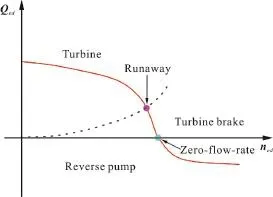
Fig. 2 (Color online) A characteristic curve (red line) of the reversible pump turbine in the generating mode with the fixed guide vane opening
3. Results and discussions
The numerical simulation mainly focuses on the reversible pump turbine in the generating mode at 21°guide vane opening. Five operational modes are selected for the analysis, including the turbine mode,the runaway mode, the turbine brake mode, the zeroflow-rate mode and the reverse pump mode. In practice, the vortex rope in the draft tube is not important as compared with the vortices in the impeller.Therefore, the iso-surface of =0.52Ris used to identify the vortices in the upstream zones of the pump turbine (not including the draft tube).
Figure 3 shows the basic characteristics and the distributions of vortices in five different operational modes. In the turbine mode, the vortices in the impeller have a periodical distribution with a concentration on the suction side of the impeller blade.Specifically, vortex rings are prominent at the inlet of the suction side of each blade. Only a few vortices can be observed in the stay vanes, the guide vanes and the vaneless space between the guide vanes and the impeller. In the turbine brake and runaway modes, the vortices in the impeller and the spiral casing show a significant non-uniform distribution among different passages, leading to the blockage of the block of part of the flow in the stay vanes and the guide vanes. In the zero-flow-rate mode, the vortex zone size increases with the generations of many tiny and disordered vortices in the flow passage. In the reverse pump mode, vortices are continuously distributed in the whole range of the flow passage.
In order to further quantify the difference of vortices in various operational modes, Fig. 4 shows a quantitative statistics of vortex areas. Along the characteristic curve shown in Fig. 2, with the decrease of the discharge, the vortex area increases with a maximum area shown in the zero-flow-rate mode (up to 6.8 m2). Furthermore, the vortex area is also relatively large in the reverse pump mode. Hence the operation of the reversible pump turbine in those regions should be avoided.

Fig. 3 (Color online) The vortices identified by =0.52R isosurface in the reversible pump turbine at 21° guide vane opening
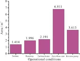
Fig. 4 (Color online) A quantitative statistics of vortex areas identified by =0.52R iso-surface under various kinds of operational conditions of the reversible pump turbine at 21° guide vane opening

Fig. 5 (Color online) Vortices identified by the R = 0.52 isosurface in the r eve rsible pump tu rbinew orkin ginthe runaway modeatthreedifferentguidevaneopenings
The runaway point is a typical working condition for the given guide vane opening. Hence, the runaway mode is selected to investigate the influences of the guide vane opening on the vortex distributions. Three guide vane openings, 6° (representing the small guide vane opening), 21° (representing the medium guide vane opening ) and 24° (with the strong S-shaped characteristic curve) are selected for the further investigation. Figure 5 shows the vortex distributions inside the reversible pump turbine at three guide vane openings in the runaway mode. In the spiral casing,the results are quite similar in terms of the vortex distributions and we will focus our attention on the vortices in the impeller. When the guide vane opening is small (6°), the distributions of vortices in the impeller and the vaneless space could be clearly visualized with a uniform distribution. However, with the increase of the guide vane opening (e.g., 24°), the flow in the impeller is deteriorated with a strong non-uniform vortex distribution.
Figure 6 further shows the statistical vortex areas at three guide vane openings of the pump turbine in the runaway mode. Generally speaking, the vortex area increases with the increase of the guide vane opening. This trend becomes more obvious in cases with large guide vane openings. For example, the vortex area adds 0.281 m2when the guide vane opening changes from 21° to 24°.
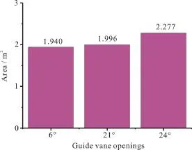
Fig. 6 (Color online) A quantitative statistics of vortex areas identified by R = 0.52 iso-surface in the reversible pump turbine working in runaway mode at three different guide vane openings
4. Conclusions and limitations
In the present paper, both qualitative and quantitative analyses of the vortices in the reversible pump turbine are made in terms of vortex distributions and areas based on the new omega vortex identification method. Five typical operational modes are employed,representing a variety of the operational modes of the reversible pump turbines in the generating mode. The conclusions can be summarized as follows:
(1) For the identifications of the vortices in the reversible pump turbine, the new omega method employs the same iso-values and avoids the potential errors induced by the user-experience-based selection of improper thresholds. Furthermore, the results of different working modes can properly compared.
(2) For the fixed guide vane openings, the vortex distributions and areas are highly related with the working modes (depending on the discharge).
(3) In the runaway mode, with the increase of the guide vane opening, the vortices in the stay/guide vanes and the impellers increase with complicated distributions and the vortices in the spiral casing remain nearly the same.
Our findings show that the new omega method can capture both the weak and strong vortices in the whole passage of the reversible pump turbine. The vortex structure in the reversible pump turbine is very complex (e.g., in terms of the vortex interactions),which is beyond the scope of the present paper.Another limitation of the present study is the lack of the experimental verifications. In the reversible pump turbines, it is extremely difficult to measure the vortex structure in the impeller accurately even in the vaneless space. Recently, Gentner et al.[25]made some measurements of the vortices in the vaneless space of the reversible pump turbine. However, the reported results in Gentner et al.[25]are quite limited (Fig. 8 of Ref. [25]) for the purpose of experimental validations.In the future, this new vortex identification method will be employed to study other complex fluid flows(e.g., the cavitation[26-29], the chaotic oscillations[30]the interface instabilities[31]and the shock wave induced flow[32]).
Acknowledgement
This work was supported by the Open Research Fund Program of Key Laboratory of Fluid and Power Machinery, Ministry of Education, Xihua University(Grant No. szjj-2017-100-1-003), the Open Foundation of National Research Center of Pumps, Jiangsu University (Grant No. NRCP201601).
[1] Zhang Y., Zhang Y., Wu Y. A review of rotating stall in reversible pump turbine [J].Proceedings of the Institution of Mechanical Engineers, Part C: Journal of Mechanical Engineering Science, 2017, 231(7): 1181-1204.
[2] Dörfler P., Sick M., Coutu A. Flow-induced pulsation and vibration in hydroelectric machinery: Engineer’s guidebook for planning, design and troubleshooting [M].London, UK: Springer-Verlag, 2013.
[3] Wu Y., Li S., Liu S. et al. Vibration of hydraulic machinery [M].Dordrecht, The Netherlands: Springer Science+Business Media, 2013.
[4] Zhang Y., Tang N., Niu Y. et al. Wind energy rejection in China: Current status, reasons and perspectives [J].Renewable and Sustainable Energy Reviews, 2016, 66(12):322-344.
[5] Zhang Y., Chen T., Li J. et al. Experimental study of load variations on pressure fluctuations in a prototype reversible pump turbine [J].Journal of Fluids Engineering,2017, 139(7): 074501.
[6] Li J. W., Zhang Y. N. Experimental investigations of a prototype reversible pump turbine in generating mode with water head variations [J].Science China Technological Sciences, 61(4): 604-611.
[7] Li D., Wang H., Qin Y. et al. Numerical simulation of hysteresis characteristic in the hump region of a pumpturbine model [J].Renewable Energy, 2018, 115: 433-447.
[8] Li D., Wang H., Qin Y. et al. Entropy production analysis of hysteresis characteristic of a pump-turbine model [J].Energy Conversion and Management, 2017, 149: 175-191.
[9] Tao R., Xiao R., Wang F. et al. Cavitation behavior study in the pump mode of a reversible pump-turbine [J].Renewable Energy, 2018, 125: 655-667.
[10] Egusquiza E., Valero C., Valentin D. et al. Condition monitoring of pump-turbines. New challenges [J].Measurement, 2015, 67: 151-163.
[11] Egusquiza E., Valero C., Presas A. et al. Analysis of the dynamic response of pump turbine impellers. Influence of the rotor [J].Mechanical Systems and Signal Processing,2016, 68: 330-341.
[12] Li J. W., Zhang Y. N., Liu K. H. et al. Numerical simulation of hydraulic force on the impeller of reversible pump turbines in generating mode [J].Journal of Hydrodynamics, 2017, 29(4): 603-609.
[13] Widmer C., Staubli T., Ledergerber N. Unstable characteristics and rotating stall in turbine brake operation of pump-turbines [J].Journal of Fluids Engineering, 2011,133(4): 041101.
[14] Hasmatuchi V., Farhat M., Roth S. et al. Experimental evidence of rotating stall in a pump-turbine at off-design conditions in generating mode [J].Journal of Fluids Engineering, 2011, 133(5): 051104.
[15] Zhang Y., Liu K., Xian H. et al. A review of methods for vortex identification in hydroturbines [J].Renewable and Sustainable Energy Reviews, 2018, 81(Part 1): 1269-1285.[16] Zhang Y., Guo Z., Du X. Wave propagation in liquids with oscillating vapor-gas bubbles [J].Applied Thermal Engineering, 2018, 133(3): 483-492.
[17] Zhang Y., Guo Z., Gao Y. et al. Acoustic wave propagation in bubbly flow with gas, vapor or their mixtures [J].Ultrasonics Sonochemistry, 2018, 40 (Part B): 40-45.
[18] Zhang Y., Qian Z., Ji B. et al. A review of microscopic interactions between cavitation bubbles and particles in silt-laden flow [J].Renewable and Sustainable Energy Reviews, 2016, 56: 303-318.
[19] Jeong J., Hussain F. On the identification of a vortex [J].Journal of Fluid Mechanics, 1995, 285: 69-94.
[20] Hunt J., Wary A., Moin P. Eddies, streams, convergence zones in turbulent flows [C].Proceedings of the Summer Program 1988 in its Studying Turbulence Using Numerical Simulation Databases, Stanford, California, USA,1988, 193-208.
[21] Liu C., Wang Y., Yang Y. et al. New omega vortex identification method [J].Science China Physics Mechanics and Astronomy, 2016, 59(8): 1-9.
[22] Liu C., Gao Y., Tian S. et al. Rortex a new vortex vector definition and vorticity tensor and vector decompositions[J].Physics of Fluids, 2018, 30(3): 035103.
[23] Dong X., Tian S., Liu C. Correlation analysis on volume vorticity and vortex in late boundary layer transition [J].Physics of Fluids, 2018, 30(1): 014105.
[24] Chen T., Zheng X. H., Zhang Y. N. et al. Influence of upstream disturbance on the draft-tube flow of Francis turbine in part-load conditions [J].Journal of Hydrody-namics, 2018, 30(1): 131-139.
[25] Gentner C., Sallsberger M., Widmer C. et al. Comprehensive experimental and numerical analysis of instability phenomena in pump turbines [C].IOP Conference Series:Earth and Environmental Science, 2014, 22(3): 032046.
[26] Zhang Y., Gao Y., Guo Z. et al. Effects of mass transfer on damping mechanisms of vapor bubbles oscillating in liquids [J].Ultrasonics Sonochemistry, 2018, 40 (Part A):120-127.
[27] Cui P., Zhang A. M., Wang S. et al. Ice breaking by a collapsing bubble [J].Journal of Fluid Mechanics, 2018,841: 287-309.
[28] Suo D., Govind B., Zhang S. et al. Numerical investigation of the inertial cavitation threshold under multi-frequency ultrasound [J].Ultrasonics sonochemistry, 2018, 41:419-426.
[29] Suo D., Jin Z., Jiang X. et al. Microbubble mediated dualfrequency high intensity focused ultrasound thrombolysis:An In vitro study [J].Applied Physics Letters, 2017,110(2): 023703.
[30] Zhang Y., Zhang Y. Chaotic oscillations of gas bubbles under dual-frequency acoustic excitation [J].Ultrasonics Sonochemistry, 2018, 40(Part B): 151-157.
[31] Zhang Y., Gao Y., Du X. Stability mechanisms of oscillating vapor bubbles in acoustic fields [J].Ultrasonics Sonochemistry, 2018, 40(Part A): 808-814.
[32] Xiang G., Wang B. Numerical study of a planar shock interacting with a cylindrical water column embedded with an air cavity [J].Journal of Fluid Mechanics, 2017,825: 825-852.
猜你喜欢
杂志排行
水动力学研究与进展 B辑的其它文章
- Numerical simulation of wave-current interaction using the SPH method *
- The influence of perforated plates on wave transmission and hydrodynamic performance of pontoon floating breakwater *
- URANS simulations of the tip-leakage cavitating flow with verification and validation procedures *
- Pressure characteristics of hydrodynamic cavitation reactor due to the combination of Venturi tubes with multi-orifice plates *
- Transport feasibility of proppant by supercritical carbon dioxide fracturing in reservoir fractures *
- Effect of blade shape on hydraulic performance and vortex structure of vortex pumps *
