石墨烯/聚酰亚胺复合膜热导率的分子动力学模拟
2018-06-28徐京城戴思畅李昊亮杨俊和
徐京城, 戴思畅, 李昊亮, 杨俊和
(1. 上海理工大学 材料科学与工程学院, 上海200093;2. 上海材料创新研究院, 上海200444)
1 Introduction
Graphene has been considered as an ideal candidate material for the future electronic applications owing to its excellent electronic and thermal properties. Plenty of experimental and theoretical researches reported that graphene presents a very high thermal conductivity at room temperature among blocky graphite, carbon nanotubes, silver and copper. The thermal conductivity of a suspended single-layer graphene has been reported in the range of 1 800-5 300 W/(m·K), with the graphene sizes of 2-10 μm[1-7]. Graphene is an ideal material for dissipating heat in integrated electronic devices, but its micrometer and nanometer scale may be a limit for practical applications. Graphene/polyimide composite film maybe a good choice, which can take full advantage of excellent thermal property of graphene, and can be embedded into electronic devices with macroscopic scale.
Improving the thermal conductivities of graphene-base products and finding an efficient and easy way to fabricate high-quality products are the continuous hotspots in the 2D-materials and electronic device fields. Nowadays, graphite films have achieved industrial production, such as Panasonic PGS graphite films. The graphite films usually are obtained after carbonization and graphitization of polyimide (PI) films[8], and present the thermal conductivity in the range of 700-1 950 W/(m·K), much higher than other materials. Theoretically, perfect graphene films possess better thermal properties than graphite films. So, graphene/polyimide composite films can be considered as a potential candidate of large-scale heat-conducting films.
Molecular dynamics (MD) simulation is a powerful method for calculating the thermal conductivities of graphene-based systems, and can provide better treatments for systems with defects. The thermal conductivities of graphene calculated by MD simulation have been reported in the range of 50-3 200 W/(m·K), with the lengths of 0.002-15 μm[9-13]. Park et al[10]. used non-equilibrium MD to investigate the length-dependent lattice thermal conductivity of graphene, and reported that the lattice thermal conductivity of graphene keep increasing in a wide range of lengths, eventually converge to a certain value. The interfacial thermal resistance is one of the main factors that influence the thermal conductivities of composite materials. Luo[14]systematically studied thermal energy transport in graphene/graphite-polymer composite systems by MD simulations, where the polymer was host materials and graphene/graphite was filling materials.
To take full use of excellent thermal property of graphene, here we propose to use graphene as host and polymer as jointing materials to construct graphene/polymer composite films (rGO/PI), expanding the micro-scale graphene to macro-scale thermal-transfer system. After the carbonization and graphitization, the polymers will form carbon-ring structures, which are treated as the bridges between graphene ribbons. We called it “molecular welding”. The welded length, width and distribution will affect the thermal transport from one graphene ribbon to another.
Pei[15]found that the thermal conductivity of hydrogenated graphene depends greatly on the hydrogen distribution and coverage. The thermal conductivity decreases rapidly with the increase of hydrogen coverage. To get the maximum thermal conductivity, in this paper, we assumed the carbon-ring structures from graphitization of polymers were perfect six-member carbon-ring structures and the action of hydrogen is not taken into account. Using classical MD simulation, we investigated the shape factors of “bridges” on the thermal conductivity of graphene/polyimide composite films, and the results were helpful to design and produce large-scale heat-conducting films.
2 Computational method and models
All simulations were performed with the classical MD simulation code Large-scale Atomic/Molecular Massively Parallel Simulator (LAMMPS)[16]. The non-equilibrium molecular dynamics (NEMD)[17]method was adopted to calculate the thermal conductivity. The adaptive intermolecular reactive empirical bond order (AIREBO)[18]and the Tersoff[19]potential are usually used to describe the carbon-carbon interactions. Based on the Boltzmann transport equation, the original Tersoff potential and Brenner potential were reported that it would underestimate the thermal conductivity of graphene, because of the inaccurate handling of phonon dispersion[20]. According to our comparations as shown in Fig. 5, the optimized Tersoff (opt-Tersoff) potential can provide more reasonable description on thermal conductivity of graphene than AIREBO potential. So, in our subsequent simulations, we chose the opt-Tersoff potential to deal with the C—C interactions.
Fig. 1 (a) shows the model for perfect graphene nanoribbons (GNRs). We set the length as the number (x) of unit cells along the heat conduction direction,and the width as the number (y) of unit cells along the armchair direction. The endmost unit cell at both ends are fixed to avoid the influence of surrounding graphene. The hot and cold region are 10 units next to the fixed ends. The thickness (h) of the graphene is typically assumed to be the graphite interlayer spacing of 0.335 nm, as same as the previous experiments and calculations, though some others chose 0.144 nm[13]. The shortest graphene ribbon in our simulations is shown in Fig. 1 (b), with x=100 and y=4. We increase the length gradually with the width remains the same, which correspond to 1.562 nm. The total number of atoms in our models changes from 1 600 to 256 000.
In the graphene/polyimide composite films, when heated at 550-700 ℃, polyimide will decompose and lead to structural rearrangement[21-23]. When the temperature rise, polyimide will further decompose and then recombine. The existence of graphene will induce the graphitization of polyimide. Nitrogen and oxygen atoms will be gas products and escape from the film. So only carbon atoms remain, and are usually present as graphene-like strips[24]. The small strips will combine graphene nanoribbons, constituting long-scale ribbons, and the strips act as bridges between GNRs, called molecular welding. Here, we consider the graphene-like strips as six-member carbon rings, just like in graphene. Fig. 2 is the sketch map of the graphene/polyimide composite structure. The length of graphene region at both ends was 19.68 nm, and the width was 1.562 nm. The length of six-member carbon rings was in the range of 0.246-19.926 nm. The hot and cold regions were set to be the same as the GNR calculations.

Fig.1 The models for thermal conductivity calculations. (a) A magnified sight over both the ends of the supercells. (b) The shortest model with x=100 and y=4.

Fig. 2 Sketch map of graphene/polyimide composite film.
The thermal transport consists of diffusive and ballistic phonon transport[25]. If the size of the model is much longer than phonon mean free path, thermal transport is mainly diffusive transport, otherwise, is ballistic transport. It has been experimentally and theoretically[10]reported the thermal conductivity in single crystalline graphene shows a logarithmic dependence on the length, even the length far greater than the mean free path of phonons[26]. The phonon mean free path of graphene is reported to be 775 nm[2]. In our simulations, the length of graphene was set from 24.6 to 7872 nm, so the heat transport style was from ballistic to the diffusive transport as a function of the length. There is a high concentration of edge defects for ballistic phonon transport. To remove the effect, periodic boundary condition is employed along both length and width directions, implying that the edge of the graphene structures is infinite. Here, we only calculated the thermal conductivity of graphene along the zigzag direction, and the electronic contributions were ignored.
All MD simulations were performed at 300 K with the time step of 0.5 fs. The NEMD simulations are performed with the canonical ensembles and the micro-canonical ensemble, the temperature was controlled by Nosé-Hoover thermostats[27]. MD simulations were carried out to reach equilibrium state at least 2 ns. When the system was in the steady state, the velocities of the atoms in the regions were adjusted automatically to bring a constant heat flux into the simulation region between the hot and cold regions. The atoms whose velocity changed in the hot and cold regions were set to be the same element, so that the non-translational kinetic energy is added or subtracted with the same amount in the hot and cold regions at every step. The temperature gradient can be established along the heat flux direction, when the simulation time was enough. We used the Fourier law to calculate the thermal conductivity from the heat flux and the temperature gradient.
(1)
WhereJis the constant heat flux across the simulation region,Sis the cross section area, ▽T=∂T/∂xis the temperature gradient along the heat flex direction.
3 Results and discussion
3.1 Thermal conductivity of graphene
Fig. 3 (a) shows the temperature distribution as a function of simulation time at different places in the graphene ribbon with x=16 000 (L=3.936 μm) and y=4. Fig. 3 (b) shows the temperature distribution as a function of the location of graphene ribbon with different simulation times. At first, the temperature was 300 K in all heat flux transport region. With the exchange of kinetic energy, the hot region tended to be hotter, and the cold region tended to be colder, the temperature gradient in transport region changed greatly. After about 6 ns MD simulations, the temperature profile came to convergence (shown as in Fig. 3(a)), and the temperature gradient didn’t change any more (shown as in Fig. 3(b)). We believed the system had reached the steady heat transfer state.

Fig. 3 (a) Temperature distribution as a function of simulation time in the graphene with x=16 000 and y=4, the vertical axis represents different locations. (b) Temperature distribution as a function of the location with different simulation times. The black squares mean 0.05 ns, red dots mean 2 ns, blue triangles mean 4 ns, green inverted triangles mean 6 ns, and purple rhombuses mean 7 ns.
Checking the temperature profile and gradient are important to ensure that we get convincing thermal conductivities. Fig. 4 shows the minimum simulation time which needed to reach a steady state as a function of the length of graphene ribbon. If the simulation time is not enough, the thermal conductivity will be overestimated.
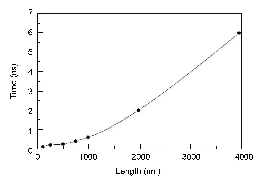
Fig.4 The times to reach the steady states as a function of the length of graphene.
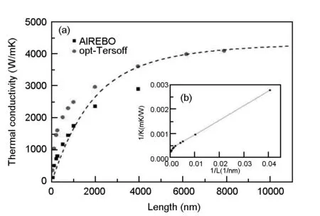
Fig. 5 (a) Thermal conductivities of graphene at 300 K as a function of the length by the opt-Tersoff and AIREBO potential. The black dashed line was obtained from the higher order heat transport equation[31]. (b) The inverse of the lattice thermal conductivity of graphene as a function of 1/L.
Fig. 5 (a) presents the comparation of the length-dependent thermal conductivities of graphene at 300 K by the opt-Tersoff and AIREBO potential. When the length is shorter than about 800 nm, the thermal conductivities increases almost linearly, in good agreement with Ref.[28]. Because it is too short for the main phonons to collide by scattering. When the length increases, the thermal conductivities increase slowly like a power function. We found that the opt-Tersoff potential performs better than AIREBO potential and finally it converges to about 4 300 W/(m·K). The results imply that the thermal conductivity of GNRs remarkably depends on the length of graphene.
Nika and coworkers proposed a model for the lattice thermal conductivity of graphene in the framework of Klemens approximation[29]. Lindsay et al. showed that flexural phonons provide the dominant contributions to the thermal conductivity of suspended graphene by using Boltzman transport equation (BTE)[30]. An effective thermal conductivity equation[31]based on Boltzman transport equation is as following:
(2)
WhereK0is the macroscopic limit ofKandlis the mean free path of phonon. We fitted the thermal conductivity with the equation (2), and plotted as the black dash line in Fig. 5 (a). The fittedK0was 4 400 W/(m·K) andlwas 655 nm, a little smaller than the reported value of 775 nm. We also plotted the reciprocal of the lattice thermal conductivity as a function of 1/L, shown as in Fig. 5 (b). We found that the line isn′t totally linear, so the linear extrapolation method[32]may underestimate the thermal conductivity.
3.2 Thermal conductivity of graphene/polyimide composite films
The simple graphene/polyimide system was divided into graphene part and polyimide part. Two graphene parts were connected together by parallel polyimide strips. First, we increased the length of polyimide part to explore the length effect with the length of graphene part kept unchanged. Fig. 6 shows the thermal conductivities of graphene/polyimide film as a function of the overall length at 300 K, the thermal conductivity of graphene part shown as black rhombus line and the polyimide part shown as red dot line. We found that the thermal conductivity of graphene part increased slightly as a function of the length of polyimide part. The thermal conductivity of polyimide part increased markedly when the overall length reached 42 nm and seemed to increase almost linearly when the overall length was more than 48 nm. However, the thermal conductivity of polyimide was far smaller than graphene, so the interface between graphene and polyimide was the main bottleneck for thermal transport in the graphene/polyimide composite film. We got the overall thermal conductivity by the length-dependent weighted average method, shown as blue triangle line in Fig. 6. The thermal conductivity of perfect graphene was also plotted as the reference, shown as the green square line. According to these results, we found that it could not improve the thermal performances only by improving the length of polyimide part.
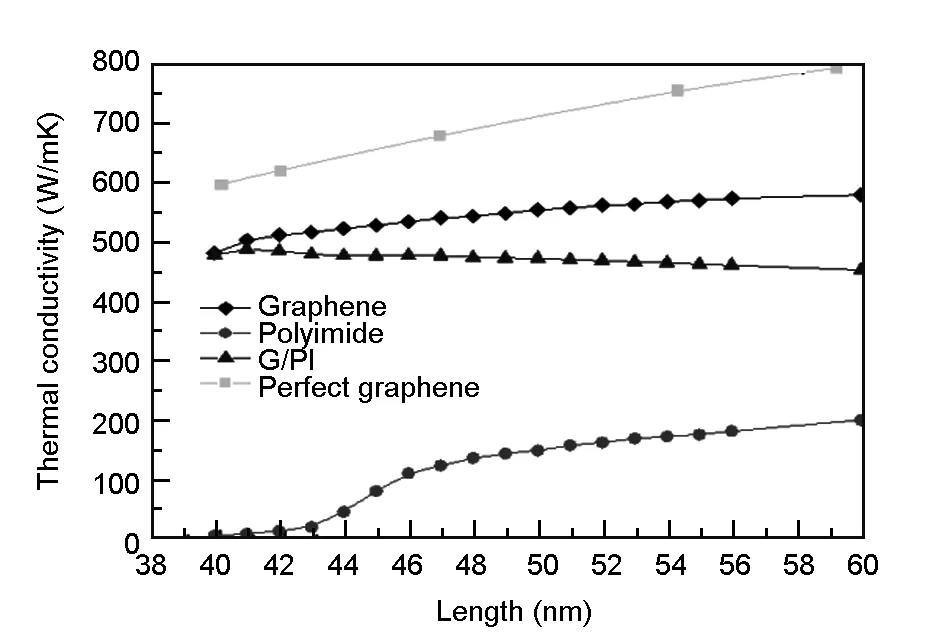
Fig. 6 The thermal conductivities of graphene/polyimide film as a function of the overall length.
Yarifard et al[33]. used NEMD simulation to investigate the thermal resistances of graphene sheets with carbon units connecting with graphene sheets. Their results indicate that the thermal resistance exhibit a decreasing trend with the height of GNRs. Therefore, the height of GNRs is the key factor in increasing the thermal conductivity of the defective graphene. Wang et al[34]. investigated the thermal transport properties of carbon units with various doping concentration of nitrogen atoms connecting GNRs. The results show that the thermal conductivity of GNRs can be greatly improved by increasing the N doping concentration to 0.87%. These results show that the thermal conductivities of GNRs are greatly influenced by the size of carbon units.
So, we also studied the influence of width and number of polyimide strips. The length and width of graphene part were fixed to 19.68 and 6.674 nm respectively. The length of polyimide strip was fixed to 13.038 nm. We designed two ways to improve the thermal conduction of graphene/polyimide film. By increasing the width of each polyimide strip, that is the width changed from 0.284 to 3.266 nm in our case. By increasing the number of polyimide strip, that iswe increased the number of polyimide strip from 2 to 8 here. Fig. 7 shows the thermal conductivities of the structure-modified graphene/polyimide film as a function of overall width of polyimide strips. We found that the thermal conductivity (black dot line) almost linearly enlarges as a function of the width of polyimide strip. When the width of each polyimide strip is close to 3.266 nm, the gap between two polyimide strips gradually shrinks to zero, then the thermal conductivity gets close to the one of graphene ribbon, presents as the highest point in Fig. 7. We set the multiple polyimide strips evenly distributed in the space of two graphene parts, as the sketch in Fig. 7. The red square line means multiple polyimide strips. The more polyimide strips are, the larger the thermal conductivity. On the other hand, increasing the number of polyimide strips is similar to increase the width, they both reduce the vacancy defects between the graphene ribbons, enhance the channels for heat conducting from one graphene ribbon to another. So, increasing the number or width of polyimide strips is an efficient way to improve the thermal conductivity of macro-scale graphene/polyimide composite film, and the impact of increasing the number is a little better than width.
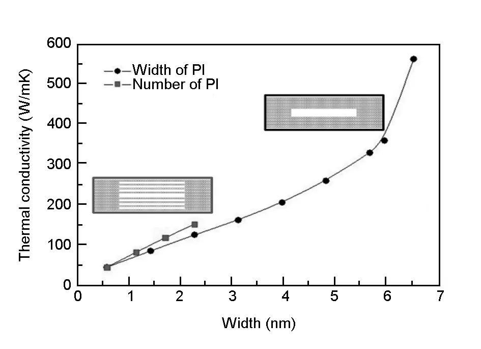
Fig. 7 The thermal conductivities of the structure-modified graphene /polyimide film as a function of total width of polyimide strips.
The differences of thermal conductivities are attributed to the vacancy defects. The defects block the heat transport between GNRs and cause more phonon scattering and lead to the decrease of thermal conduc tivity[35]. Further explanations can be obtained by determination of the phonon density of states (PDOS),which shows the different excitable phonon frequencies. We calculated the PDOS by the Fourier transform of the velocity autocorrelation function, shown as in Fig. 8, and the polyimide atoms don't change the relative frequency and magnitude of the phonons. The phonon frequencies can be divided into three regions: the low-frequency (0-20 THz), the medium-frequency (20-50 THz) and the high-frequency (50-60 THz) region. Usually, the vibrations of high -frequency phonons transfer thermal energy. With our models, when increasing the length of polyimide strip, the intensity of peak at 50 THz decreased distinctly. We thought that because the phonon scattering happens at the interfaces of graphene and polyimide, and the boundaries of polyimide strips. Increasing the length of polyimide strip didn’t change the interfaces, but generated more boundaries, resulting in more phonon scattering, and then decreased the strength of high-frequency phonon vibrations and heat conductions.
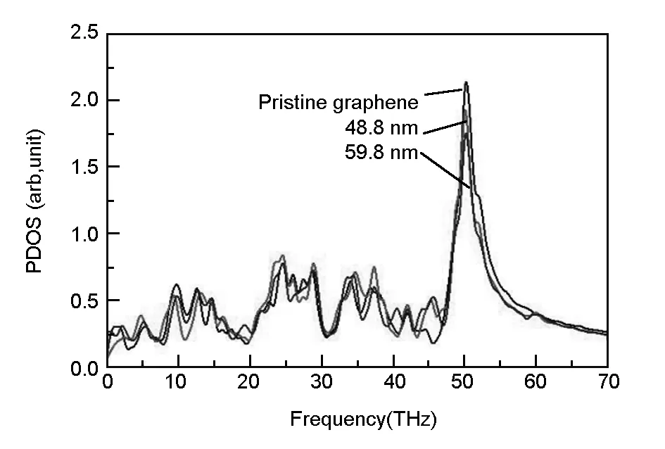
Fig. 8 Phonon density of states of graphene/polyimide films.

Fig. 9 Thermal conductivity of rGO/PI: (a) experiment and (b) MD simulation.
We propose a “molecular welding” technique to fabricate flexible and ultrathin reduced graphene/polyimide (rGO/PI) films with a considerable enhancement in in-plane thermal conductivity. As shown in Fig. 9(a), the in-plane thermal conductivity of rGO/PI-1% (1% is the weight percentage of PI) film is 802.3 ± 20.5 W/(m·K), which is 21.9% higher than that of the pristine rGO film. The thermal conductivities of rGO/PI decrease as a function of the concentration of PI. Compared with our simulation results as shown in Fig. 9(b), though the overall thermal conductivity is a little smaller than the experimental results (because of the small size of model), the overall trend is the same. The results show that molecular welding of polyimide can improve the thermal conductivity of rGO/PI with the concentration of PI from 1%-3%, the overall thermal conductivity decreases as a function of the concentration of PI.
4 Conclusion
The thermal conductivities of pristine graphene and graphene/polyimide composite films were calculated by the non-equilibrium molecular dynamics method. The thermal conductivity of graphene presents an increasing and converged trend, depending on the length of model. The graphitized polyimide strips can be used to connect graphene ribbons to form macro-scale composite films. Polyimide strip can improve the thermal conductivity of graphene film and can get the highest thermal conductivity at the concentration of PI from 1% to 3 %. Increasing the number or width of polyimide strip can obviously improve the heat transfer characteristics. It is helpful for understanding the effect of polyimide in the heat transfer, and for designing the macro-scale composite films with excellent thermal performances.
Acknowledgments
Computations were carried out using Hujiang HPC cluster at USST, Shanghai Supercomputer Center and National Supercomputing Center in Shenzhen in China.
[1] Balandin A A, Ghosh S, Bao W, et al. Superior thermal conductivity of single-layer graphene[J]. Nano Letters, 2008, 8(3): 902.
[2] Ghosh S, Calizo I, Teweldebrhan D, et al. Extremely high thermal conductivity of graphene: Prospects for thermal management applications in nanoelectronic circuits[J]. Applied Physics Letters, 2008, 92(15): 151911.
[3] Ghosh S, Bao W, Nika D L, et al. Dimensional crossover of thermal transport in few-layer graphene[J]. Nature Materials, 2010, 9(7): 555-558.
[4] Chen S, Moore A L, Cai W, et al. Raman measurements of thermal transport in suspended monolayer graphene of variable sizes in vacuum and gaseous environments[J]. ACS Nano, 2011, 5(1): 321-328.
[5] Cai W, Moore A L, Zhu Y, et al. Thermal transport in suspended and supported monolayer graphene grown by chemical vapor deposition[J]. Nano Letters, 2010, 10(5): 1645-1651.
[6] Lee J U, Yoon D, Kim H, et al. Thermal conductivity of suspended pristine graphene measured by Raman spectroscopy[J]. Physical Review B, 2011, 83(8): 081419.
[7] Chen S, Wu Q, Mishra C, et al. Thermal conductivity of isotopically modified graphene[J]. Nature Materials, 2012, 11(3): 203-207.
[8] Takeichi T, Eguchi Y, Kaburagi Y, et al. Carbonization and graphitization of Kapton-type polyimide films prepared from polyamide alkyl ester[J]. Carbon, 1998, 36(1): 117-122.
[9] Pei Q X, Sha Z D, Zhang Y W. A theoretical analysis of the thermal conductivity of hydrogenated graphene[J]. Carbon, 2011, 49(14): 4752-4759.
[10] Park M, Lee S C, Kim Y S. Length-dependent lattice thermal conductivity of graphene and its macroscopic limit[J]. Journal of Applied Physics, 2013, 114(5): 053506.
[11] Liu Y, Yang H, Liao N, et al. Investigation on thermal conductivity of bilayer graphene nanoribbons[J]. RSC Advances, 2014, 4(97): 54474-54479.
[12] Wei Z, Ni Z, Bi K, et al. In-plane lattice thermal conductivities of multilayer graphene films[J]. Carbon, 2011, 49(8): 2653-2658.
[13] Guo Z, Zhang D, Gong X G. Thermal conductivity of graphene nanoribbons[J]. Applied Physics Letters, 2009, 95(16): 163103.
[14] Luo T, Lloyd J R. Enhancement of thermal energy transport across graphene/graphite and polymer interfaces: a molecular dynamics study[J]. Advanced Functional Materials, 2012, 22(12): 2495-2502.
[15] Pei Q X, Sha Z D, Zhang Y W. A theoretical analysis of the thermal conductivity of hydrogenated graphene[J]. Carbon, 2011, 49(14): 4752-4759.
[16] Plimpton S. Fast parallel algorithms for short-range molecular dynamics[J]. Journal of Computational Physics, 1995, 117(1): 1-19.
[17] Alaghemandi M, Algaer E, Böhm M C, et al. The thermal conductivity and thermal rectification of carbon nanotubes studied using reverse non-equilibrium molecular dynamics simulations[J]. Nanotechnology, 2009, 20(11): 115704.
[18] Stuart S J, Tutein A B, Harrison J A. A reactive potential for hydrocarbons with intermolecular interactions[J]. The Journal of Chemical Physics, 2000, 112(14): 6472-6486.
[19] Tersoff J. Modeling solid-state chemistry: Interatomic potentials for multicomponent systems[J]. Physical Review B, 1989, 39(8): 5566.
[20] Lindsay L, Broido D A. Optimized Tersoff and Brenner empirical potential parameters for lattice dynamics and phonon thermal transport in carbon nanotubes and graphene[J]. Physical Review B, 2010, 81(20): 205441.
[21] Hatori H, Yamada Y, Shiraishi M, et al. The mechanism of polyimide pyrolysis in the early stage[J]. Carbon, 1996, 34(2): 201-208.
[22] Hishiyama Y, Igarashi K, Kanaoka I, et al. Graphitization behavior of Kapton-derived carbon film related to structure, microtexture and transport properties[J]. Carbon, 1997, 35(5): 657-668.
[23] Konno H, Nakahashi T, Inagaki M. State analysis of nitrogen in carbon film derived from polyimide Kapton[J]. Carbon, 1997, 35(5): 669-674.
[24] Shen B, Zhai W, Zheng W. Ultrathin flexible graphene film: an excellent thermal conducting material with efficient EMI shielding[J]. Advanced Functional Materials, 2014, 24(28): 4542-4548.
[25] Balandin A A. Thermal properties of graphene and nanostructured carbon materials[J]. Nature Materials, 2011, 10(8): 569-581.
[26] Majee A K. Extrinsic Effects on Heat and Electron Transport in Two-Dimension Van-Der Waals Materials-A Boltzmann Transport Study[M]. Masters Theses, University of Massachusetts, 2016.
[27] Hoover W G. Canonical dynamics: equilibrium phase-space distributions[J]. Physical Review A, 1985, 31(3): 1695.
[28] Mingo N, Broido D A. Carbon nanotube ballistic thermal conductance and its limits[J]. Physical Review Letters, 2005, 95(9): 096105.
[29] Nika D L, Ghosh S, Pokatilov E P, et al. Lattice thermal conductivity of graphene flakes: Comparison with bulk graphite[J]. Applied Physics Letters, 2009, 94(20): 203103.
[30] Lindsay L, Broido D A, Mingo N. Flexural phonons and thermal transport in graphene[J]. Physical Review B, 2010, 82(11): 115427.
[31] Alvarez F X, Jou D. Memory and nonlocal effects in heat transport: from diffusive to ballistic regimes[J]. Applied Physics Letters, 2007, 90(8): 083109.
[32] Schelling P K, Phillpot S R, Keblinski P. Comparison of atomic-level simulation methods for computing thermal conductivity[J]. Physical Review B, 2002, 65(14): 144306.
[33] Yarifard M, Davoodi J, Rafii-Tabar H. Computation of the thermal resistance in graphene sheets with a rectangular hole[J]. Computational Materials Science, 2017, 126: 29-34.
[34] Wang C, Yang H, Fan H, et al. Heat transfer regulation of hole defect graphene by nitrogen doping[J]. Applied Physics A, 2015, 121(2): 549-553.
[35] Nika D L, Pokatilov E P, Askerov A S, et al. Phonon thermal conduction in graphene: Role of Umklapp and edge roughness scattering[J]. Physical Review B, 2009, 79(15): 155413.
