A feedback-retransmission based asynchronous frequency hopping MAC protocol for military aeronautical ad hoc networks
2018-05-17JinhuiTANGYequnWANGShufuDONGQiluSUNGuoceHUANG
Jinhui TANG,Yequn WANG,Shufu DONG,Qilu SUN,Guoce HUANG
aCollege of Information and Navigation,Air Force Engineering University,Xi’an 710077,China
bNational Key Laboratory of Airspace Technology,Beijing 100085,China
cPostdoctoral Scienti fic Research Workstation,Westone Information Industry INC.,Chengdu 610041,China
dPostdoctoral Scientific Research Station,University of Electronic Science and Technology of China,Chengdu 610054,China
1.Introduction
A Mobile Ad hoc NETwork(MANET)has the advantages of simple deployment,rapid networking,easy to expand,strong anti-destroying ability,etc.,which make it widely used in social networks,1,2wireless sensor networks,3,4vehicle networks,5,6and so on.Introducing technologies of MANETs into aeronautical communications brings a new application named Aeronautical Ad hoc NETwork(AANET),7,8which helps to build a flexible and efficient platform for exchanging and sharing air information,and is also favored by the military.
Besides the general characteristics of an MANET,a military AANET also has its own particularities which are mainly classified into two categories.9–12The first one is that air nodes have characteristics of wide coverage,fast-changing topology,and long propagation delay.For example,air nodes may distribute in a huge range of thousands of kilometers and the speed of an aircraft can be 2 Mach.Furthermore,the propagation time of packets may be longer than the transmission time,which will not happen in an MANET.The other is that military aeronautical communication has rigid demands for low latency and high reliability,especially in the application of attacking time-sensitive targets,which expects that 99%of total packets’end-to-end delay should not go beyond 10 ms,and more than 99%of total packets are transmitted successfully.The resulted problems because of these particularities of a military AANET need to be considered during the design of a network infrastructure and communication protocols.In this paper,we only consider the MAC protocol of an AANET,because this protocol has a crucial influence on the system performance.
The existing MAC protocols of AANETs can be divided into three classi fications.The first one is the reservation MAC protocol,represented by IEEE 802.11 and its implementations.13,14Within an MANET,because of the short distance between two adjacent nodes,the propagation time of these two nodes is much shorter than the transmission time,and thus the influence of the propagation time on the protocol performance analysis can be ignored.However,for an AANET,since the scale of the network gets enlarged,the propagation time between two nodes is also increased,which may be as long as the transmission time,and therefore,the propagation time has to be taken into account of the protocol performance analysis.Furthermore,the nodes of these MAC protocols need multiple control frames to reserve a channel before transmitting packets,which makes the propagation time more serious and the ratio of channel utilization declined,and as a result,the protocol performance degrades sharply.Thus,the reservation MAC protocol only works well in a network with a short node distance.The second one is the scheduling MAC protocol,15represented by Time Division Multiple Access(TDMA)and its improvements.Since the length of a time slot is determined by the maximal propagation time,the maximal transmission time of packets,and the processing time,this kind of protocol works on time synchronization of a network and is suitable for traffic which is delay-insensitive and has a large capacity.The third one is the FH anti-jamming MAC protocol,including synchronous FH16and asynchronous FH.17The synchronization FH has a strict demand for time synchronization,and its characteristic of slow changing topology makes it suitable in a civil AANET.For an application which has a higher demand for timeliness and reliability such as a military AANET,a Statistics Priority-based Media Access(SPMA)control protocol18was proposed,which was developed from the CSMA protocol and adopted the mechanism of channel occupancy statistic.When the value of channel occupancy statistic reaches a predetermined threshold,this protocol will restrict the process of packet access,which will ensure that the network is always in a light load status.Based on the SPMA protocol,adaptive mechanisms for a frequency hopping MAC and a priority-based adaptive frequency hopping MAC were designed in Refs.19,20,respectively.However,they still have some disadvantages to be solved.Firstly,they all belong to the Non-Feedback-Retransmission based asynchronous frequency hopping Media Access(NFRMA)control protocol and only adapt to the very light load scenarios which can lessen the collisions of packets;as a consequence,the performances of system throughput and channel utilization are degraded.Secondly,they use the average packet end-to-end delay as the timeliness evaluation standard,which may not be suitable for time-sensitive information in a military aeronautical network.Lastly,most of existing research works only validate their ideas by simulations,in other words,they are lack of theoretic analysis with modeling and calculating.
The general simulation method,queuing theory,and Markov model have been used in the proposed protocol of an AANET.As to the simulation method,which is the most basic,simplest,and most effective method,simulation tools include OPNET,NS-2,Qualnet,Exata,and so on.These simulation tools can assess the performances of protocols,and the difference between these simulation tools is only the code portability.The queuing theory method can illustrate the process of packets queuing service,and adopted models are M/G/1/K,M/D/1/K,M/M/1/K,and so on.These queuing models can be used to compute the system throughput,packet success probability,and the distribution of packet waiting time.While the Markov model method can accurately exhibit the state transition course of nodes,this method can be used to analyze the average value and distribution function of packet end-toend delay.
For the above problems,a new MAC protocol named feedback-retransmission based asynchronous FRequency hopping Media Access(FRMA)control protocol is proposed in this paper.Through techniques of burst communications,asynchronous FH,channel coding,and mechanism of feedback retransmission,the timeliness and reliability of information transmission are ensured.Besides,compared with the NFRMA protocol,the proposed scheme has an outperformance in system throughput.
2.Protocol description
Assume that all nodes in a network are equal and randomly distributed within an L×L×H km spatial region,and constitute a fully connected network.The transceiver is composed by one transmitting channel and multiple receiving channels the number of which are equal to the number of FH points.The length of a packet is fixed,and its arrival rate obeys the Poisson distribution.The transmit buffer is a First Input First Output(FIFO)queue,and a newly arrived packet will be discarded automatically when the buffer is full.Since all nodes have their own FH patterns,a packet is split into several bursts and then modulated according to the FH pattern of the receiving node before being transmitted.
2.1.Multi-packet reception
In an FH network,there are two ways to realize the function of multi-packet reception.One way is to equip with multiple FH receivers which can process signal detection,timing acquisition,signal receiving,and demodulation for data streams from different sources.The other way is to equip with several general receivers which can receive traffic packets at fixed frequencies and get a complete recovery through Analog-Digital(A/D)conversion and FH pattern matching.With a comparison between these two ways,the second approach has the advantage of less cost.The composition of receiving equipment and the processing procedure are shown in Fig.1.
Fig.1 indicates that FH pattern matching can recover complete information from traffic packets,and these packets exist in the form of bursts.The burst distributions before FH pattern matching are shown in Fig.2.Fig.2 shows the transmitted packets by nodes A,B,and C via four channels,i.e.,f1-f4,as well as the received packets at the node D.Since the A,B,and C three nodes use the FH pattern of node D,and the initial times and propagation times of the traffic packets for A,B,and C nodes are different,thus the received bursts at node D could be collided as the receiving buffer of node D shown in Fig.2.Through FH pattern matching,these bursts can be recovered into three data streams,and their FH patterns are consistent.
2.2.Feedback-retransmission mechanism
Similar to the ARQ protocol,let ACK and NCK represent that packets are received correctly and incorrectly,respectively.Set maximum retransmission times for all packets,and a bigger retransmit number means that the packet is transmitted successfully with a higher ratio;however,a longer delay is also resulted in.When the maximum retransmission times are small,the time delay is also small,but the reliability declines consequently.Therefore,the value of the maximum retransmission times should be given according to a tradeoff between reliability and timeliness in a practical application.
Since the burst communication and FH technology are utilized,the control frame can only be divided into several bursts because of its short length.Such a limited number of bursts are unfavorable to do FH pattern matching,so an independent control channel may be more suitable.
2.3.Process of state transition
The state transition process of the FRMA protocol is shown in Fig.3.
All nodes in the network work according to the following steps:
Step 1.Start from the ‘initialization/idle” state.If a new packet arrives,it will be inserted into the tail of the transmitting buffer directly.Then the first packet in the queue is selected to be handled.After channel coding,packet dividing,and FH modulation,this packet is transmitted in a burst manner,and then that node enters into the state of ‘waiting acknowledge”.
Step 2.In the state of ‘waiting acknowledge”,if a new packet arrives,it will be inserted into the tail of the transmitting buffer directly.If the control frame of ACK arrives,it indicates that the current transmission is successful.If the control frame of NCK arrives,or the waiting acknowledge is timeout,it means that the current transmission is failed.Then the times of that packet’s transmission are examined whether it reaches the maximum,and the result determines discarding or retransmitting of the next step.
Step 3.By checking the transmitting buffer,the node enters into the state of ‘idle” if it is empty;otherwise,the first packet in the queue is transmitted and enters into the state of ‘waiting acknowledge”.
3.Modeling analysis
3.1.Basic parameters
To easily distinguish,we call packets received from the upper level as traffic packets and packets entering into the network as data packets.A definition of symbols used in the modeling analysis is listed in Table 1.
3.2.Queuing theory
For any node,new packets can be considered as customers in the service system,and the process of transmitting can be considered as providing service,so it can be viewed as a typical queuing system.In this system,the arriving process of a new packet obeys the Poisson distribution,and the serving time obeys the independent identical distribution.There is one server,and the size of the transmitting buffer is K.All of these can be described as an M/D/1/K queuing model.
Let akbe the probability of k sums of packets coming during one packet service time.Let pkbe the probability of k sums of packets waiting in the transmitting buffer under a steady state.Let ηkbe the probability of k sums of residual packets just after one packet leaves the transmitting buffer under a steady state.Let Xkbe the number of residual packets just after the kth packet leaves the transmitting buffer.Because the nodes of the network are independent and the collision of packet transmission for each node has no relation with the unsuccessful times of pre-transmission,according to Refs.21–23,Xkcan be considered as a discrete Markov process,and the state transition course is shown in Fig.4.
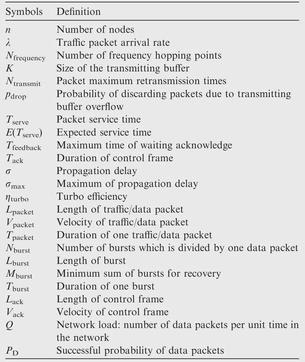
Table 1 definition of symbols used in the modeling analysis.
Through Markov analysis,the state transition matrix can be written as
Set η=[η0,η1,...,ηK-1],and the following equations can be obtained:
ρ can be expressed as
According to the M/D/1/K queuing model,pkcan be written as
akcan thus be mathematically expressed as
When λ and K are fixed,take Eq.(6)into Eq.(1),and then take the resulted Eq.(1)into Eq.(2).Combining the resulted Eq.(2)with Eq.(3),we can get K+1 equations with K+1 parameters,which are ηi,i∈ [0,K-1]and E(Tserve).With the achieved K+1 equations,the parameters ηi,i∈ [0,K-1]and E(Tserve)can be obtained.Take the obtained E(Tserve)into Eq.(4),we can get the value of ρ.With Eq.(5),K+1 equations of parameters pi,i∈ [0,K]can be formed,and piis finally obtained.
pdropcan be written as
3.3.Network load
The mutual interference between data packets may affect correct receiving.Ignore the failure of control frames.Let PSibe the probability of traffic packets which have been transmitted i times and succeeded finally,and let Libe the number of data packets added to the network load which are caused by one traffic packet with i times of transmission.Let PFbe the probability of traffic packets which have reached the maximum retransmission times and failed finally,and the load of the network increases by LFaccordingly.All of these parameters can be expressed as
Let Q1be the number of data packets added to the network load which are caused by one traffic packet transmission.Based on Eq.(8),Q1can be expressed as
With Eqs.(7)and(9),the network load can be written as
3.4.Artwork/Figure
When the traffic load is low,the sending buffer of each node is empty most of the time,so a new packet arriving from the upper level will be transmitted immediately;thus the process of data packets entering into the network can approximately be thought to obey the Poisson distribution,and the corresponding probability density function can be expressed as
Any data packet in the network may overlap with some other data packets and get interfered,that is shown in Fig.5.
As shown in Fig.5,let Di, i=1,2,3...be the ith data packet pre- and post-current data packet. Let φi,i∈ [1,Nburst]be the probability of two adjacent data packets having an ((i-1)Tburst,iTburst]interval,and φNburst+1denotes the probability of having a(Tpacket,∞)interval,where Tpacket=NburstTburst.From the above analysis,the following equations can be obtained:
De fine I(i,k),i∈ [1,Nburst],k ∈ [1,Nburst+1],the probability that k-1 bursts are interfered in the case of two data packets having an ((i-1)Tburst,iTburst] interval, and I(Nburst+1,k),k ∈ [1,Nburst+1],the probability of k-1 bursts to be interfered in the case of two packets having a(Tpacket,∞)interval.
De fine g(i,k),i∈ [0,Nburst],k ∈ [0,Nburst],the probability that k bursts are interfered in the case of two packets having i overlapping bursts.g(i,k)can be expressed as
Step 1.Analysis of D1’s effect on current data packet.
(1)There are Nburst-i+1 overlapping bursts if two packets have an interval of ((i-1)Tburst,iTburst],i∈ [1,Nburst],and the probability that k-1 bursts are interfered can be expressed as I(i,k)=g(Nburst-i+1,k-1).
(2)There are no overlapping bursts if two packets have an interval of(Tpacket,∞),and the probability that k-1 burstsare interfered can be expressed as I(Nburst+1,k)=g(0,k-1).
From the above analysis,I(i,k)can be written as
According to Eqs.(12)–(16),the expected number of interfered bursts due to being overlapped by D1can be expressed as
Step 2.Analysis of D2’s effect on current data packet.
D2’s effect on current data packet is related to the interval between D1and D2,as well as the interval between D1and current data packet.
(1)If D1and D2has an interval of(0,Tburst],D2’s effect on current data packet is analyzed as follows.
(A)There are Nburst-i overlapping bursts if the interval between current data packet and D1is((i-1)Tburst,iTburst],i∈ [1,Nburst-1],and the probability that k-1 bursts are interfered can be expressed as I(i,k)=g(Nburst-i,k-1).(B)There are no overlapping bursts if the interval between current data packet and D1is((Nburst-1)Tburst,∞),and the probability that k-1 bursts are interfered can be expressed as I(Nburst,k)=g(0,k-1).I(i,k)can be expressed as
Therefore,in the case that the interval between D1and D2is(0,Tburst],the expected sum of interfered bursts due to overlapping can be expressed as
(2) If D1and D2have an interval of((j-1)Tburst,jTburst],j ∈ [1,Nburst-1],D2’s effect on current data packet is analyzed as follows.
(A)There are Nburst-j-i+1 overlapping bursts if the intervalbetween currentdata packetand D1is((i-1)Tburst,iTburst],i∈ [1,Nburst-j],and the probability that k-1 bursts are interfered can be expressed as I(1,k)=g(Nburst-j-i+1,k-1).
(B)There are no overlapping bursts if the interval between current data packet and D1is((Nburst-j)Tburst,∞),and the probability that k-1 bursts are interfered can be expressed as I(Nburst-j+1,k)=g(0,k-1).I(i,k)can be expressed as
Therefore,in the case that the interval between D1and D2is((j-1)Tburst,jTburst],j∈ [1,Nburst-1],the expected number of interfered bursts due to overlapping can be expressed as
(3)If D1and D2have an interval of((Nburst-1)Tburst,∞),the interval between current data packet and D2is(Tpacket,∞),and there are no overlapping bursts.
According to Eqs.(18)–(21),the expected sum of interfered bursts due to overlapping with D2can be expressed as
Theorem 1.A data packet,consisting of Nburstbursts,overlaps with packets A and B.The probability density functions of the interfered bursts’number are IA(k)and IB(k),k ∈ [0,Ntransmit].Then the probability density function of union effects can be expressed as
The following subsection is the derivation of Theorem 1:
The instance that k bursts are interfered due to overlapping with A and B can be classi fied as follows:
Firstly,the probability of k bursts overlapping with A and zero burst overlapping with B can be written as
Secondly,the probability of k bursts overlapping with A and one burst overlapping with B can be written as
Thirdly,the probability of k bursts overlapping with A and j,j∈ [0,k]bursts overlapping with B can be written as
Fourthly,the probability of k-1 bursts overlapping with A and j,j∈ [1,k]bursts overlapping with B can be written as
From the above analysis,the formulation of IAB(k)can be obtained as
In order to lessen the computational burden,once the load of the network is not heavy,only two packets before the current data packet and two packets after the current data packet are considered during analyzing the interference of the current data packet.
Then according to Eq.(23),the probability density function of the total number of interfered bursts can be obtained and written as I(k).
Assume that a data packet can be recovered if Mburstout of Nburstbursts are correct.Then PDcan be expressed as
3.5.traffic packet service time
Tfeedbackcan be expressed as
If the traffic packet is transmitted successfully after i,i∈ [1,Ntransmit]times of trying,then the service time it occupies can be expressed as
If the traffic packet reaches the maximum retransmission times,then the service time it occupies can be written as
Then the expectation of the traffic packet service time can be calculated as
According to Eqs.(7),(10),(17),(23),and(33),when the parameters n, λ,Nburst,Mburst,Tack,Tfeedback,and σmaxare known,the values of Q,E(Tserve),and PDcan be calculated.
4.Performance analysis
4.1.Packet success probability
Set the packet success probability as the ratio of the number of successful packets to the total number of packets generated,which is denoted by Pright.
There are two reasons for a failure of traffic packets transmission.The first is transmitting buffer over flow,and the second is that the transmit times of a packet reach the maximum and fail eventually.According to Eqs.(7)and(8),Prightcan be expressed as
4.2.System throughput
Set the system throughput as the bit number of successful packets per unit time,and it is denoted by Sthroughput.
According to Eq.(34),Sthroughputcan be expressed as
4.3.Packet end-to-end delay
Set the packet end-to-end delay as the interval from the time of a traffic packet entering into the transmitting buffer to the time of being received successfully,and the packet access time as the interval from the time of a traffic packet moving out the transmitting buffer to the time of being received successfully.
The computation procedure of the packet end-to-end delay is shown as follows.
Step 1.Probability density function of the propagation delay.
Let g(i)be the probability of the propagation delay which is iTburst.The probability density function can be obtained through discrete Laplace transformation,and it is denoted by G(z).
Step 2.Probability density function of the packet access time.
If a traffic packet transmits i, i∈ [1,Ntransmit]times and finally succeeds, the access time is denoted as(i-1)Tfeedback+Tpacket+σ,and the probability density function can be written as
According to Eqs.(8)and(36),the probability density function of the packet access time can be calculated as
Step 3.Probability density function of the packet end-toend delay.
When a new traffic packet arrives,if the number of packets waiting in the transmitting buffer is j,j∈ [0,K-1],then the probability density function of the packet end-to-end delay can be expressed as
According to Eqs.(5)and(38),the probability density function of the packet end-to-end delay can be calculated as
The distribution function of the packet end-to-end delay can be obtained by residue theorem as
where ξ denotes the maximum packet end-to-end delay,and it is written as ξ=KNtransmitTfeedback.
It is assumed that more than 99%of traffic packets’end-toend delays are required less than 10 ms.Then according to Eq.(40),when λ is fixed,t0.99can be obtained via T(t)=0.99.However,the obtained t0.99has a direct relationship with λ when the network scale and packet length are fixed,and when λ changes,the obtained t0.99also varies.Since the equation of T(t|t=10ms)=0.99 is too complex to get an exact value of λ,thus we can only get its approximation according to the distribution of T(t)with different λ.
The average value of packet end-to-end delays can be calculated as
5.Performance evaluation
In this section,simulations are provided to investigate the performance of the FRMA protocol,including(A)the approximation accuracy of theoretical derivation for the FRMA protocol,(B)the performance difference between FRMA and NFRMA,and(C)analysis of the FRMA protocol’s ability in providing low latency service.
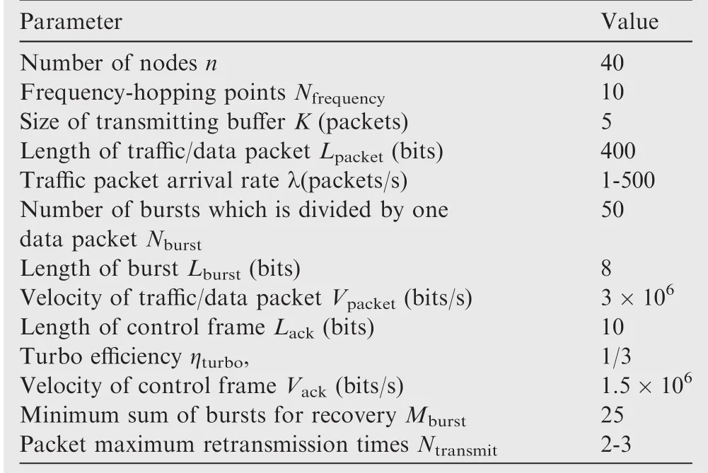
Table 2 Simulation parameters.
In an air-to-ground attack mission,we dispatch 40 fighters composed by 4 groups to strike enemy’s important target,and the flight path of each group is shown in Fig.6.The flight speed is 100 km/h during take-off,and the maximum and minimum distances between each two groups are 300 km and 100 km,respectively.Within our area,the flight speed is 600 km/h,while once the fighters move into the enemy area,group 1 and group 4 speed up to 1200 km/h and the other two groups speed up to 1100 km/h,quickly.The distance between any two groups is more than 2 km.These groups have cooperative information transmission.The route and speed for coming back are the same as those for the attack,and the whole time of the mission is 2 hours.We use NS-2 to simulate and analyze.
The simulation parameters are listed in Table 2.
5.1.Comparison between calculation and experimental results
Assume that the maximum retransmission times of a traffic packet are 3,and then the packet success probability,the system throughput,and the average packet end-to-end delay under different packet arrival rates are shown in Fig.7.
As shown in Fig.7(a),in the case of λ ≤ 200 packets/s,the experimental result of packet success probability is consistent with the calculation derivation,but the calculation result is slightly higher than that of experiment if λ > 200 packets/s.The reasons can be summarized as the following.(A)To reduce the computation complexity,this paper puts forward a hypothesis that the time interval of data packets obeys a negative exponential distribution.(B)In the analysis of the packet collision model,only neighboring packets’colliding effect is considered.These two assumptions are only correct in cases of lighter network loads.As shown in Fig.7(b)and(c),the experimental results of the system throughput and the average packet end-to-end delay are consistent with the analytical derivations.
5.2.Performance comparison between FRMA and NFRMA
Assume that the maximum retransmission times of a traffic packet are 2,and then the performances of the packet success probability,the system throughput,and the average packet end-to-end delay for FRMA and NFRMA are shown in Fig.8.
As shown in Fig.8(a),to ensure Pright≥99%,the NFRMA protocol must work in the condition of λ ≤ 42 packets/s,while the FRMA protocol demands λ ≤ 130 packets/s,so the improvement degree is 210%.As shown in Fig.8(b),the system throughput of NFRMA is 6.6×105bits/s in the case of λ=42 packets/s,while the system throughput of FRMA is 2.1 × 106bits/s in the case of λ =130 packets/s.In a word,the improvement degree is 215%.As shown in Fig.8(c),the packet average end-to-end delay of the NFRMA protocol is 0.98 ms,while that of the FRMA protocol is 1.27 ms in the case of λ =130 packets/s.In a word,to ensure Pright≥ 99%,the consumption time of FRMA is 0.29 ms more than that of the NFRMA protocol,so the deteriorative degree is 29.6%.
Through comparison and analysis,we can see that when the traffic load is very light,these two protocols have no big difference.When the traffic load is not heavy,the proposed FRMA protocol can significantly improve the system throughput with the price of a small delay.However,when the traffic load is heavy,these two protocols both deteriorate sharply.Therefore,the proposed protocol outperforms the existing protocol with normal traffic load,and when the traffic load is heavy,these MAC protocols are not sufficient,and the mechanism of flow control should be taken into account further,which is out of our scope.
5.3.Analysis of the FRMA protocol’s ability in providing low latency service
Assume that the maximum retransmission times of traffic packet are 3,and then the packet end-to-end delay distribution of FRMA is shown in Fig.9.
As shown in Fig.9,in the case of λ=130 packets/s,95%of the packet end-to-end delays are less than 4.96 ms,and 99%are less than 7.72 ms.In the case of λ=150 packets/s,95%of the packet end-to-end delays are less than 5.57 ms,and 99%are less than 8.59 ms.In the case of λ=170 packets/s,95%of the packet end-to-end delays are less than 6.81 ms,and 99%are less than 9.48 ms.In the case of λ=192 packets/s,95%of the packet end-to-end delays are less than 8.13 ms,and 99%are less than 11.4 ms.
From Fig.9,we can see that if more than 99%of traffic packets’end-to-end delays are required less than 10 ms,we can get the ranges of a reasonable maximum λ with different delay distribution lines.The simulated results show that the delay distribution corresponding to the maximum λ lies between the square line and the downward-pointing triangle line.
6.Conclusions
(1)The analytical derivation can reflect the performance of the FRMA protocol in the condition of light network load.
(2)By using the mechanism of feedback retransmission,the system throughput of the FRMA protocol increases greatly with a price of adding a little packet end-toend delay.
(3)Although the packet average end-to-end delay of the FRMA protocol is a little higher than that of the NFRMA protocol,with an increase of the traffic load,the proportion of long-delay packets also increases accordingly.Therefore,traffic load should be restricted according to specificdemandson timelinessand reliability.
Acknowledgement
This study was supported by the National Natural Science Foundation of China(No.61501496).
References
1.Xia F,Liaqat HB,Deng J,Wan JF,Das SK.Overhead control with reliable transmission of popular packets in ad-hoc social networks.IEEE Trans Veh Technol 2016;65(9):7647–61.
2.Hao F,Li S,Min GY,Kim H-C,Yau SS,Yang LT.An efficient approach to generating location-sensitive recommendations in adhoc social network environments.IEEE Trans Serv Comput 2015;8(3):520–33.
3.Saman S,Kavian YS,Tarhani M,Rashvand HF.Geographical multi-layered energy-efficient clustering scheme for ad hoc distributed wireless sensor networks.IET Wireless Sens Syst 2016;6(1):1–9.
4.Priyatosh M,De Swades.New reservation multiaccess protocols for underwater wireless ad hoc sensor networks.IEEE J Oceanic Eng 2015;40(2):277–91.
5.Xie HH,Boukerche A,Loureiro AAF.MERVS:A novel multichannel error recovery video streaming protocol for vehicle ad hoc networks.IEEE Trans Veh Technol 2016;65(2):923–35.
6.Siva T P,Tim B,Robert HK.Initial evaluation of an IEEE 802.11s-based mobile ad-hoc network for collaborative unmanned aerial vehicles.Proceedings of ICCVE;2013 December 2–6;Las Vegas.Piscataway,NJ:IEEE Press.2013.p.145–50.
7.Ghosh S,Nayak A.ACPM:an associative connectivity prediction model for AANETProceedings of ICUFN;2016 July 5-8.Vienna.Piscataway,NJ:IEEE Press;2016.p.605–10.
8.Mickael R,Fabien G,Alain P.An enhanced 1-hop clustering algorithm for publish/subscribe systems in AANETs.Proceedings of DASC;2015 September 13–17;Czech Republic.Piscataway:IEEE Press;2015.p.2D2-1–2D2-6.
9.Justin PR,Abdul J,Egemen KC,Perrins E,Sterbenz JPG.Highlydynamic cross-layered aeronautical network architecture.IEEE Trans Aerosp Electron Syst 2011;47(4):2742–65.
10.Nguyen TXM,Yoshikazu M,Chaiyachet S.Connectivity analytical modeling for a single flight path ad hoc aeronautical network.Proceedings of ECTI;2010 May 19–21;Chiang Mai,Thailand.Piscataway:IEEE Press;2010.p.51–55
11.Konstanca N,Nicolas B.A new method based on motion primitives to compute 3D path planning close to helicopters’flight dynamics limits.Proceedings of ICMAE;2016 July 18–20;London.Piscataway:IEEE Press;2016.p.411–415
12.Kam WL,Brian GF.Simultaneous classi fication and ranging of direct fire weapons using an asynchronous acoustic sensor network.Proceedings of ISSNIP;2011 Dec 6–9;Adelaide,SA.Piscataway:IEEE Press;2011.p.425–430.
13.IEEE Std 802.11.IEEE standard for local and metropolitan area networks,part 11:Wireless LAN medium access control(MAC)and physical layer(PHY)specifications.Piscataway,NJ:IEEE Press;2011.
14.Aymen F,Domenico G,Vincent L.Evaluation of self-positioning algorithms for time-of- flight base localization.Proceedings of WiOpt;2016 May 9–13;Tempe,AZ.Piscataway:IEEE Press;2016.p.1–8.
15.Helmle S,Dehm M,Kuhn M,Lieckfeldt D,Pesch D.Feedback interval for link adaptation in TDMA-based single-carrier VHF narrowband mobile ad-hoc networks.Electron Lett 2014;50(3):221–3.
16.Smart G,Deligiannis N,Surace R,Loscri V.Decentralized timesynchronized channel swapping for Ad Hoc wireless networks.IEEE Trans Veh Technol 2016;65(10):8538–53.
17.John CH,James AS,inventor;Rockwell Collins Inc.,Method and architecture for TTNT symbol rate scaling modes.United States patent US 7839900;2010 November 23.
18.Stephen MC,Kelli AH,Scott JFZ,inventor;Rockwell Collins Inc.,Statistical priority-based multiple access system and method.United States patent US 7680077;2010 March 16.
19.Wang YQ,Ye XY,Qi YJ,Zhang HY.Adaptive mechanism for frequencyhoppingMAC.JXi’dianUniv2013;40(5):78–85[Chinese].
20.Wang YQ,Yang F,Huang GC,Zhang HY,Guo JX.Media access control protocol with differential service in aeronautical frequency hopping ad hoc networks.J Softw 2013;24(9):2214–25[Chinese].
21.Bianchi G.Performance analysis of the IEEE 802.11 distributed coordination function.IEEE J Sel Areas Commun 2000;18(3):535–47.
22.Yao Y,Cai WD,Hilaire V,Koukam A,Wang C.Statistical analysis technique on ad hoc network topology dynamic characteristics:Markov stochastic process.Telecommun Syst 2013;53(1):33–45.
23.Chenga HJ,Sua ZH,Xiongb NX,Xiao Y.Energy-efficient node scheduling algorithms for wireless sensor networks using Markov random field model.Inf Sci 2016;329:461–77.
杂志排行

CHINESE JOURNAL OF AERONAUTICS的其它文章
- Mechanical wear debris feature,detection,and diagnosis:A review
- Generic functional modelling of multi-pulse auto-transformer rectifier units for more-electric aircraft applications
- Erosion degradation characteristics of a linear electro-hydrostatic actuator under a high-frequency turbulent flow field
- Modeling and analysis of mover gaps in tubular moving-magnet linear oscillating motors
- An adaptive-order particle filter for remaining useful life prediction of aviation piston pumps
- Variable load failure mechanism for high-speed load sensing electro-hydrostatic actuator pump of aircraft