A Tensor—based Enhancement Algorithm for Depth Video
2018-05-07YAOMENG-qiZHANGWEI-zhong
YAO MENG-qi ZHANG WEI-zhong


【Abstract】In order to repair the dark holes in Kinect depth video, we propose a depth hole-filling method based on tensor. First, we process the original depth video by a weighted moving average system. Then, reconstruct the low-rank sensors and sparse sensors of the video utilize the tensor recovery method, through which the rough motion saliency can be initially separated from the background. Finally, construct a four-order tensor for moving target part, by grouping similar patches. Then we can formulate the video denoising and hole filling problem as a low-rank completion problem. In the proposed algorithm, the tensor model is used to preserve the spatial structure of the video modality. And we employ the block processing method to overcome the problem of information loss in traditional video processing based on frames. Experimental results show that our method can significantly improve the quality of depth video, and has strong robustness.
【Key words】Depth video; Ttensor; Tensor recovery; Kinect
中圖分类号: TN919.81 文献标识码: A 文章编号: 2095-2457(2018)05-0079-003
1 Introduction
With the development of depth sensing technique, depth data was increasingly used in computer vision, image processing, stereo vision and 3D reconstruction, object recognition etc. As the carriers of the human activities, video contains a wealth of information and has become an important approach to get real-time information from the outside world. But due to the limitation of the device itself, gathering sources, lighting and other reasons, the depth video always contains noise and dark holes. Thus the quality of video is far from satisfactory.
For two dimensional videos, the traditional measures to denoising and repairing adopted filter methods based on frames[1]. But the continuous frames have a lot of redundant information, which will bring us much trouble. This representation method ensures the completeness of the videos inherent structure.
2 Tensor-based Enhancement Algorithm for Depth Video
2.1 A weighted moving average system[2]
When Kinect captures the video, the corresponding depth values are constantly changing, even at the same pixel position of the same scene. It is called Flickering Effect, which caused by random noise. In order to avoid this effect, we take the following measures:
1)Use a queue representing a discrete set of data, which saves the previous N frames of the current depth video.
2)Assign weighted values to the N frames according to the time axis. The closer the distance, the smaller the frame weight.
3)Calculate the weighted average of the depth frames in the queue as new depth frame.
In this process, we can adjust the weights and the value of N to achieve the best results.
2.2 Low-rank tensor recovery model
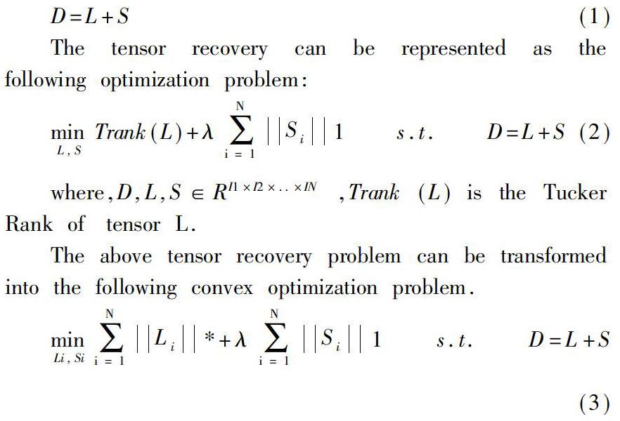
Low-rank tensor recovery[3] is also known as high order robust principal component analysis (High-order RPCA). The model can automatically identify damaged element in the matrix, and restore the original data. The details are as follows: the original data tensor D is decomposed into the sum of the low rank tensor L and the sparse tensor S,
The tensor recovery can be represented as the following optimization problem:
where,D,L,S∈RI1×I2×..×IN ,Trank(L) is the Tucker Rank of tensor L.
The above tensor recovery problem can be transformed into the following convex optimization problem.
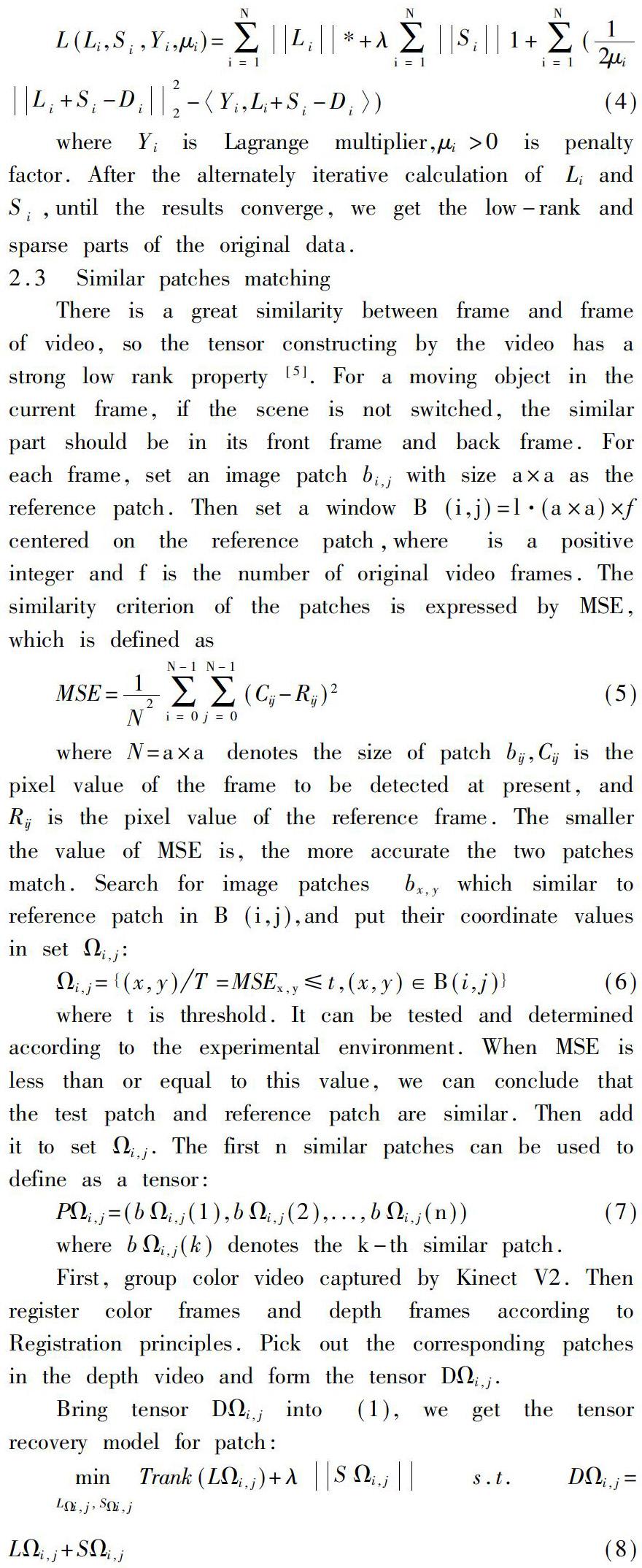
Aiming at the optimization problem in (2), typical solutions[4] are as follows: Accelerated Proximal Gradient (APG) algorithm, Augmented Lagrange Multiplier (ALM) algorithm. In consideration of the accuracy and fast convergence speed of ALM algorithm, we use ALM algorithm to solve this optimization problem and generalize it to tensor. According to (2), we formulate an augmented Lagrange function:
2.3 Similar patches matching
There is a great similarity between frame and frame of video, so the tensor constructing by the video has a strong low rank property[5]. For a moving object in the current frame, if the scene is not switched, the similar part should be in its front frame and back frame. For each frame, set an image patch bi,j with size a×a as the reference patch. Then set a window B(i,j)=l·(a×a)×f centered on the reference patch,where is a positive integer and f is the number of original video frames. The similarity criterion of the patches is expressed by MSE, which is defined as
where N=a×a denotes the size of patch bij,Cij is the pixel value of the frame to be detected at present, and Rij is the pixel value of the reference frame. The smaller the value of MSE is, the more accurate the two patches match. Search for image patches bx,y which similar to reference patch in B(i,j),and put their coordinate values in set :
where t is threshold. It can be tested and determined according to the experimental environment. When MSE is less than or equal to this value, we can conclude that the test patch and reference patch are similar. Then add it to set i,j. The first n similar patches can be used to define as a tensor:
3 Experiment
3.1 Experiment setting
The experiment uses three videos to test. Some color image frames of the test video are as listed in Figure 1.
Fig.1. Test video captured from the Kinect sensor (a) Background is easy, the moving target is the man.(b) Background is complex, the moving target are two men, and they are far from the camera.(c) Background is messy, and the moving target is the man in red T-shirt, he is near the camera.
3.2 Parameter setting
In the same experimental environment, we compare our method with VBM3D[6] and RPCA. For VBM3D and RPCA algorithm, the source code is used, provided by the literature, to get the best result. For our algorithm, the parameters are all set empirically, so that the algorithm can achieve the best results. In all tests, we set some parameters as follows: the number of test frames is 120; the number of similarity patches is 30; the size of patch is 6*6, the maximum number of iterations is 180; tolerance thresholds are ?著1=10-5,?着2=5×10⁻⁸. We use Peak Signal-to-Noise Ratio (PSNR)[7] to quantatively measure the quality of denoised video images. And the visual effect of video enhancement can be observed directly.
3.3 Experiment results
In order to measure the quality of the processed image, we usually refer to the PSNR value to measure whether a handler is satisfactory. The unit of PSNR is dB. So the smaller the value, the better the quality. As can be seen from table 1, in the same experimental environment, the effect of the proposed method is better than other methods in the three groups of test videos. Fig.2 shows the enhancement result of moving object after removing the background by our method .
As we can see from Figure 3, the proposed method in this paper can remove noise very well and basically restore the texture structure of the video. The effect of video enhancement is satisfactory.
Fig.2. The enhancement result of moving object after removing the background by our method. (a) (b)(c)are depth video frame screenshot in original depth video a,b,c. (d)(e)(f) The enhancement results of moving object in video a, video b and video c respectively.
Fig.3. Depth video enhancement result (a)(b)(c) Depth video frame screenshot in original depth video a, video b and video c respectively. (d)(e)(f) The enhancement results in video a, video b and video c respectively.
Fig.4. The comparison results(partial enlarged view) of our method and other methods(VBM3D and RPCA method). (a)(b)(c) The enhancement results(partial enlarged view) of depth video a, video b and video c respectively with our method. (d)(e)(f) The enhancement results(partial enlarged view) of depth video a, video b and video c respectively with VBM3D.(g)(h)(i) The enhancement results(partial enlarged view) of depth video a, video b and video c respectively with RPCA.
We compare the results of our method used in this article with those of the VBM3D and RPCA method. In order to make the experimental results clearer, we put the partial magnification. By comparison, we can see that our method is superior to the other methods in denoising, repairing holes and maintaining edges.
4 Conclusion
In this paper, we propose a tensor-based enhancement algorithm for depth video, combining tensor recovery model and video patching. Experimental results show that the proposed method can effectively remove the interference noise and maintain the edge information. It is superior to the traditional methods in the processing of depth video.
References
[1]Liu J, Gong X. Guided inpainting and filtering for Kinect depth maps[C]. IEEE International Conference on Pattern Recognition, 2012:2055-2058.
[2]Zhang X, Wu R. Fast depth image denoising and enhancement using a deep convolutional network[C]//Acoustics, Speech and Signal Processing (ICASSP), 2016 IEEE International Conference on. IEEE, 2016: 2499-2503.
[3]Xie J, Feris R S, Sun M T. Edge-guided single depth image super resolution[J]. IEEE Transactions on Image Processing, 2016, 25(1): 428-438.
[4]Compressive Principal Component Pursuit, Wright, Ganesh, Min, Ma, ISIT 2012, submitted to Information and Inference, 2012.
[5]Chang Y J, Chen S F, Huang J D. A Kinect-based system for physical rehabilitation: a pilot study for young adults with motor disabilities.[J]. Research in Developmental Disabilities, 2011, 32(6):2566-2570.
[6]Bang J Y, Ayaz S M, Danish K, et al. 3D Registration Using Inertial Navigation System And Kinect For Image-Guided Surgery[J]. 2015, 977(8):1512-1515.
[7]Zhongyuan Wang, Jinhui Hu, ShiZheng Wang, Tao Lu Trilateral constrained sparse representation for Kinect depth hole filling[J]. Pattern Recognition Letters, 65 (2015) 95–102
