Recent developments in aqueous ammonia-based post-combustion CO2 capture technologies
2018-04-08HaiYu
Hai Yu
CSIRO Energy,10 Murray Dwyer Circuit,Mayfield West,NSW 2304,Australia
Keywords:Aqueous ammonia NH3 Post-combustion capture Ammonia loss Regeneration energy Amines
A B S T R A C T Aqueous ammonia(NH3)is a promising alternative solvent for the capture of industrial CO2 emissions,given its high chemical stability and CO2 removal capacity,and low material costs and regeneration energy.NH3 also has potential for capturing multiple flue gas components,including NOx,SOx and CO2,and producing value-added chemicals.However,its high volatility and low reactivity towards CO2 limit its economic viability.Considerable efforts have been made to advance aqueous NH3-based post-combustion capture technologies in the last few years:in particular,General Electric's chilled NH3 process,CSIRO's mild-temperature aqueous NH3 process and SRI International's mixed-salts(NH3 and potassium carbonate)technology.Here,we review these research activities and other developments in the field,and outline future research needed to further improve aqueous NH3-based CO2 capture technologies.
1.Introduction
The intensive use of coal,oil and other fossil fuels for power generation and other industrial applications has results in excessive emissions of carbon dioxide(CO2),which is regarded as the major contributing factor to global warming.CO2emissions from fossil-fuel combustion and industrial processes account for about 78%of the total greenhouse gas emission increase between 1970and2010[1].Tohaveatleasta50%chanceoflimitingtheaverageglobal temperature increase to 2°C by 2100(2°C Scenario,or 2DS),CO2emissions from fuel combustion and industrial processes must decline significantly–by 60%by the year 2060–and carbon neutrality in the energy system must be reached by 2100[1].
Carbon capture and storage(CCS)involves separating carbon dioxide from emission sources,compressing it and transporting it to a suitable location for permanent storage.CCS is regarded as one of key approaches to significantly reduce CO2emissions from fossil-fuel combustion and industrial processes.In the 2DS,CCS technologies are required to deliver 14%of the cumulative CO2emission reductions,with around 142 Gt CO2captured in the period to 2060[1].
Post-combustion capture(PCC)is regarded as the most feasible,near-term technology to significantly reduce CO2emissions from existing coal-fired power plants,due to the following potential benefits:
•It is a commercially available and mature technology that has a lower technology risk than competing technologies.
•It can be retrofitted to existing power plants(or integrated with new infrastructure)to achieve a range of CO2reductions,from partial retrofit to full capture capacity.
•Renewable technologies can potentially be integrated with PCC—for example,low-cost solar thermal collectors can provide the heat required to separate CO2from solvents.
•PCC can be used to capture CO2from a range of sources—smelters,kilns,steel works,and coal and gas-fired power stations.
2.Review of Technologies
PCC technologies can use adsorbents,absorbents,membrane,chemical looping and cryogenic processes.The most advanced,near-term technologies use amine-based solvents or solvents that contain amino groups such as ammonia and amino-acid salts[2–4].Some of these technologies have been commercially realised in coal-fired power stations,including the Boundary Dam and WA Parish power plants[2,4].Table 1 summarises the recent development of these technologies.
Despite the significant advancements in PCC technology,its commercial deployment is still hindered by many challenges,including the following[17–19]:
•The material and capital cost is high.
•Solvents degrade during CO2capture,leading to generation of toxic wastes and costly solvent make-up.
•It has high levels of parasitic energy consumption.Installing the current MEA capture process in coal-fired power plants would decrease overall thermal efficiency by 25%–40%and raise electricity costs by 70%–100%.
•The amine solvent has poor SOxtolerance,which requires a deep cut inSO2content(ideally to levels below 10 mg·L-1).The presence of NO2may facilitate the formation of carcinogenic nitrosamines from the use of some amines in PCC and their potential release into the environment.Further treatment of the CO2-containing flue gas to minimise the adverse impact of SO2and NOxcan add a significant cost.

Table 1 Recent development of near-term post-combustion CO2 capture(PCC)technologies
Aqueous NH3is a promising alternative solvent for CO2capture from coal-fired power stations and many other industrial flue gases,and has many advantages over amine-based solvents[20]:
•It is the cheapest and most stable solvent.It does not degrade to generate hazardous waste.The environmental and health effects of NH3are well studied and are much less than that of amines.
•It has a higher CO2removal capacity and a lower regeneration energy than other amine-based solvents.
•Aqueous NH3can capture multiple components(NOx,SOx,CO2and Hg)and produce value-added products such as ammonium sulfate and ammonium nitrate, which are widely used as fertilisers.
In a previous paper[20],we reviewed research into the development of aqueous NH3-based capture technologies up to 2013 and compared its performance with other solvents,in particular monoethanolamine(MEA).Intensive research at various scales has been carried out to understand both the fundamental and practical aspects of aqueous NH3-based PCC processes.The thermo-chemical properties of the CO2–NH3–H2O system are well understood and can be satisfactorily predicted by several models.Rate-based process models for the capture of CO2in packed columns have been developed and validated against experimental results,including those from Munmorah pilot-plant trials.
Bench-scale and pilot-plant-scale investigations have demonstrated some of the benefits of aqueous NH3when used for CO2capture in various industries.They include low material cost and regeneration energy;high solvent stability,CO2removal efficiency and purity of CO2product;and the ability to capture both CO2and SO2in an integrated process.However,the same investigations reveal challenges that limit the technical and economic viability of aqueous NH3-based capture processes[20].These include the following:
•NH3absorbs CO2at a slower rate than the standard MEA solution under their respective operational conditions.This results in larger columns and higher capital costs.
•NH3is a hazardous gas that strongly irritates the throat,eyes and respiratory system,threatening the health of human beings and animals.The Safe Work Australia and United States National Institute of Occupational Safety and Health recommend that NH3concentrations in workplace air should not exceed 25 μl·L-1[21,22].It is also a major contributor to secondary aerosols in the atmosphere and can alter the kinetics of their formation.NH3loss is high during the absorption process,and its recovery of NH3requires a high consumption of cooling water and additional refrigeration energy.
•Solid precipitation is a practical issue that can lead to blockages and unintentional plant shutdown.
The assessment of overall performance using both equilibrium and rate-based process models show that the chilled NH3process(CAP)leads to a lower net efficiency penalty than a MEA-based process,subject to the availability of low-temperature cooling water.This may limit the application of NH3processes to locations where either lowtemperature cooling water or low-temperature waste heat is available.
Since 2013,considerable research efforts have been devoted to addressing the key challenges facing aqueous NH3-based CO2capture and improving its economic viability.The research mainly focuses on three processes:GE's CAP,CSIRO's mild-temperature aqueous NH3process and SRI International's mixed-salts technology.In this paper,we review these research activities and other developments in the field,and outline future research to advance the technology.
2.1.GE's chilled NH3 process(CAP)
The process was initially called Alstom Power's CAP[23].When GE acquired Alstom's power and grid business in 2015,the technology was renamed accordingly.The original process consists of the following steps[24]:
(1)Flue gas cooling to condense water vapour and remove residual emissions from the flue gas.
(2)CO2absorption in highly concentrated NH3solution at low temperatures(5–15°C),which produces a slurry containing ammonium bicarbonate.
(3)CO2regeneration.The slurry is concentrated to increase its solid content and regenerated at higher temperatures(above 80°C)and moderate pressure(2 MPa)in the stripper.This aims to increase the CO2content in the rich solvent and reduce the sensible heat in the generation process.
(4)NH3recovery.Some of the NH3in the solvent can evaporate to the flue gas in the CO2absorber.An NH3absorption and regeneration unit is needed to recycle NH3to the CO2capture process.
Fig.1 shows a schematic of the GE's CAP(solid mode).
Pilot-plant experience led to a shift from the original configuration(solid mode)to the non-solid mode in which no solid formation is involved.Fig.2 shows the modified CAP,in which solid-handling equipment such as the hydrocyclone is removed[25].Trials showed that the solid mode did not benefit energy savings and instead introduced difficulties in handling solid precipitation and maintaining operational stability[24].
CAP has been evaluated at different scales including bench,pilot and demonstration levels.The results from these tests have been reviewed by Augustsson et al.[24]and are summarised in Table 2.
Using the updated design basis for CAP from the work done during the Mountaineer project,a technical and economic study was carried out on its integration with a 750-MW net,ultrasupercritical,pulverised coal-fired power plant to achieve 90%CO2removal[24].The calculated efficiency loss was 9.5%points and the levelised cost of electricity(LCOE)increased by 59 USD·(MW·h)-1,nearly doubling the case without carbon capture.Detailed operational conditions were not available in public domain.

Fig.1.Schematic of GE's chilled-ammonia process(solid mode).Reproduced from[23].

Fig.2.Non-solid chilled-ammonia process.Reproduced from[25].
Jilvero et al.evaluated the techno-economic performance of CAP added to an existing,state-of-the-art,coal-fired power plant with an electric efficiency of 47.2%(based on low heat value)[26].The capture process included flue gas cooling,CO2absorption and regeneration,NH3recovery and CO2compression and is similar to that shown in Fig.2(non-solid process).The solvent had an NH3concentration of 15 wt%and a lean CO2loading of 0.25.The absorber was operated at 10°C and atmospheric pressure and the stripper at 2 MPa.The CO2product was compressed to 7.5 MPa.Heat from the steam cycle was taken from existing intermediate and low-pressure extractions to the stripper and the NH3stripper.Plant integration was regarded as a matter of matching the operating temperatures of the heat requirements of the capture process to the pressure levels in the steam cycle.Epsilon Professional 10.0 was employed to simulate the power plant and a rate-based process model built in Aspen Plus was used to assess the CO2capture.
Jilvero et al.'s technical evaluation showed that electrical output of the power plant dropped by 9.2%at 90%CO2capture efficiency,while the economic evaluation showed that the rich/lean heat exchanger was the most expensive capital item.This is because in the NH3-based capture process,the absorption liquid flow rate was higher and the temperature difference across the lean/rich heat exchanger was larger than those in amine-based processes.Hence,a much larger heat exchanger was required.In addition,a shell-and-tube heat exchanger was selected to reduce possible plugging due to solid precipitation in the rich solvents.A compact plate-and-frame heat exchanger has narrow channels and is more likely to be blocked by precipitates.The overall analysis showed that under the conditions investigated,the use of NH3as a CO2absorbent is economically competitive compared with amine-based absorbents.In Jilvero et al.'s study,access to lowtemperature(5°C)cooling water was assumed to be available.If the cooling water was at 20°C,the heat requirement of the NH3abatement cycle would be about half that of the CO2capture cycle.The performance of NH3-based PCC is therefore highly dependent on access to low-temperature cooling water.
Hanak et al.evaluated alternative retrofit options using a validated,highly reliable process model for a coal-fired power plant and a ratebased process model for CAP[27,28].The power station had a gross power output of 580 MW and a net thermal efficiency of 38.5%(high heat value).The CO2capture process included flue gas cooling,CO2absorption,regeneration and compression,but did not include NH3recovery.The flue gas and lean solvent were chilled to 7 and 10°C,respectively,before entering the absorber.The CO2product was compressed to 11 MPa.A sensitivity analysis showed that the lowest parasitic load occurred at a 12.5 wt%NH3concentration and 0.29 lean loading with the stripper operated between 1.25 and 1.75 MPa.Salt did not precipitate in the column under these operating conditions.
Hanak et al.'s integration study showed that a basic process integration decreased power plant net efficiency by 10.9%points.Advanced integration configurations investigated included substituting the let-down and throttle valves with let-down and back-pressure steam turbines,integrating heat for steam de-superheating and integrating an auxiliary turbine.The study found that overall process performance would be improved by 1.7%efficiency points if the steam pressure was controlled using a combination of a let-down turbine and a back-pressure turbine.If steam extracted from the steam cycle is also de-superheated using HP feedwater before it is sent to the PCC unit,the net efficiency is improved by 1.7%points compared to the base case.An efficiency improvement of 2.1%–2.2%points(a net efficiency penalty of 8.7%–8.8%)was reached when the novel configuration proposed in this study was implemented.This involved coupling a new two-stage or a single-stage auxiliary steam turbine with the boiler feedwater pump.
2.2.CSIRO mild-temperature aqueous NH3-based CO2 capture
CSIRO has been developing an aqueous NH3-based PCC technology for application under Australian conditions since 2008.Previous pilotplant trials at Delta Electricity's Munmorah Power Station demonstrated the technical feasibility of the process and confirmed some of the expected benefits[29,30].With support from the Australian Government and Australian National Low Emissions Coal Research and Development,CSIRO has worked with several universities in a combined processmodelling and bench-scale testing approach.The aim is to develop and evaluate innovative ideas to address issues limiting the economic viability of the aqueous NH3-based process,and to develop an advanced version.Fig.3 shows the schematic flow sheet of CSIRO's advanced NH3PCC process.
The advanced process consists of a SO2removal and NH3recycle unit,and a CO2absorption and desorption unit.It builds on the process tested previously at Munmorah Power Station and incorporates severalinnovative features as discussed below.The performance of the advanced process was assessed by a rigorous rate-based process model for CO2and SO2capture in aqueous NH3,which was validated by the pilot-plant results.

Table 2 Summary of test results for GE's chilled-ammonia process(CAP)[24]
2.2.1.Integrated flue gas cooling,SO2 removal and NH3 recovery
The integrated process can simultaneously cool flue gas,remove SO2and recover NH3.As shown in Fig.3(NH3recycle&SO2removal unit),it consists of a wash column,in which the vaporised NH3is recovered by wash water;a pretreatment column,in which the heat contained in the high-temperature flue gas is used to regenerate NH3in the wash water and recycle it to the CO2absorber via the flue gas;and a water separation unit for maintaining water balance.SO2is removed in the pretreatment column.Its presence in the wash water helps to recover NH3from the wash column,producing ammonium sulphite that can be used to make ammonium sulfate fertiliser.
Rigorous rate-based process modelling and bench-scale experimental work showed that the integrated process can recycle and reuse >99%NH3and remove >99%SO2with very low energy consumption.Results from a typical case study are shown in Fig.4.The flue gas contains 200 μl·L-1SO2and the NH3concentration in the gas stream entering the wash column is assumed to be 11500 μl·L-1.Detailed simulation conditions can be found in[32].
The NH3from the combined NH3recycling and SO2recovery system is split in two[33].As shown in Fig.4a,close to 97%of NH3is recycled to the CO2absorber as NH3make-up,while the remainder is used for SO2capture,where it remains in the solution in the form of(NH4)2SO3and NH4HSO3.As shown in Fig.4b,the NH3concentration emitted to flue gas after washing increases gradually to 25 μl·L-1after 385 cycles,and then experiences a sharp rise to 50 μl·L-1at 450 cycles.Before this point,the wash water needs to be treated for removal of NH3and SO2in the wash water.The average NH3concentration after 450 cycles is 11.2 μl·L-1,which could be a reference of total amount control of NH3.
The predicted SO2removal efficiency in this work was more than 99%(Fig.5a).With more cycles(increasing operation time),the captured SO2was accumulated in the solution in the form of(NH4)2SO3and NH4HSO3,with the(NH4)2SO3being the dominant SO2-containing species,as shown Fig.5b.The concentrated sulphur-containing solution needed further treatment before these chemicals reached saturation in wash water.Commercial processes are available for the production of(NH4)2SO4fertiliser using sulphur-containing solutions generated from the aqueous NH3-based SO2removal process[34].This new process can eliminate conventional flue gas desulfurisation(FGD)and produce value-added products,potentially saving hundreds of millions of dollars.
2.2.2.Integration of NH3 process with process improvements
The advanced NH3process incorporates the following process improvements.

Fig.3.Schematic flow sheet of the advanced NH3 post-combustion capture process developed by CSIRO.Reproduced from[31]).

Fig.4.(a)Predicted NH3 reuse efficiency and(b)NH3 emission concentration at the outlet of the wash column(b)as a function of number of cycles.Reproduced from[29].
Two-staged absorption(Fig.6):the lean solvent,rich in free NH3,is introduced to the middle of the absorber to achieve fast CO2absorption(Stage 1 absorption),and then enters the top of the column to recover NH3from the gas(Stage 2 absorption).This configuration can significantly reduce NH3slip in the absorption process by more than 50%compared with single-stage absorption[31].
Elevating CO2absorption temperature to ambient conditions(20–30°C)and using relatively high NH3concentrations(6 wt%–10 wt%):This can avoid both solid precipitation and the substantial energy input for solvent chilling while also improving the CO2absorption rate.NH3loss can be resolved by the NH3recycle unit and staged absorption shown in Fig.6.
New stripper configuration:Rich split and inter heating(Fig.7).Stripper rich split involves splitting one portion of the cold,rich solvent and pumping it to the top of the stripper,while the rest of the rich solvent is heated and introduced to the middle of the stripper.This configuration uses the cold,CO2-rich solution to cool the uprising hot gas vapour and recover the NH3from the vapour.No external stream is involved in the modification.The process can help eliminate solid precipitation in the stripper overhead condenser,and reduce reboiler duty and cooling water consumption.
Fig.8 shows the effect of the rich-split ratio(mass ratio of split solvent to the total rich solvent)on(a)energy consumption and(b)distribution of three heat components:heat of CO2desorption,heat of vaporisation and sensible heat.The rich-split process significantly decreased the heat of vaporisation with increasing split fraction,which was favourable for lowering condenser duty and the subsequent regeneration duty.However,at higher split fractions,the cold split stream started to cool the stripper and more sensible heat was required to heat the split solvent to the required temperature,which increased reboiler duty.The heat of vaporisation and sensible heat were therefore competing with each other,resulting in an appropriate split fraction that maximised the savings of energy duty.As shown in Fig. 8b, when a 0.05 split fraction was applied,the total energy duty reached a minimum of 3.28 MJ·(kg CO2)-1with reboiler duty of 2.89 MJ·(kg CO2)-1and condenser duty of 0.39 MJ·(kg CO2)-1.These values are much lower than those without rich split[35].

Fig.5.(a)Predicted SO2 capture efficiency and SO2 emission level and(b)(NH4)2SO3 and NH4HSO3 concentrations as a function of number of cycles.Reproduced from[33].
The inter-heating process exchanges heat between the hot,lean stream leaving the bottom of the stripper and the semi-lean solvent extracted from the middle of the stripper,before the hot,lean stream goes to the main cross-exchanger(Fig.9).The process uses the heat in the hot,lean stream and reduces reboiler and condenser duty simultaneously.
This process design aims to reduce reboiler duty and condenser duty in two ways.First,it recycles the high-quality,high-temperature heat in the hot,lean solvent stream,which elevates the overall temperature along the stripper column.Second,it reduces the energy loss associated with steam generation by reducing the temperature of the rich solvent entering the top of stripper column.Fig.10a shows that the interheated stripper changes the distribution of temperature profiles along the stripper column,increasing the temperatures at the stripper bottom sections while decreasing the temperatures at the top sections.This can reduce the energy consumption of sensible heat and heat of vaporisation(Fig.10(b)).As a consequence of inter-heating,the reboiler duty decreases to 3.00 MJ·(kg CO2)-1[35].

Fig.6.Schematic of two-stage absorption.

Fig.7.Schematic of rich-split process.
The process that combines rich split and inter-heating can achieve the benefits associated with each process.When a 0.05 split fraction and inter-heating process is combined,the regeneration duty is reduced to 2.46 MJ·(kg CO2)-1,while the cooling duty of the condenser is only 0.24 MJ·(kg CO2)-1.This is a reduction of 24.8%in reboiler duty and 83.4%in condenser duty compared with the reference case,which is very competitive and promising in terms of energy savings[35].
2.2.3.Improvement of solvent formulation
We have identified several additives that can promote CO2absorption in aqueous NH3.These include piperazine(PZ),2-methyl PZ,and the environmentally friendly amino-acid salts of taurine,sarcosine and proline.Introducing these five promoters significantly increases CO2mass transfer in the solvent,but at the expense of greater NH3vapour losses.As shown in Figs.11 and 12,the mass transfer coefficients of CO2in amino-acid salts and NH3mixtures are close to those in MEA but generally lower under the conditions studied.In comparison,NH3mixed with PZ or 2-methyl PZ can achieve mass transfer coefficients matching those obtained using MEA.
Stopped-flow spectrophotometry was used to elucidate the mechanism involved in the reaction of CO2(aq)with NH3/promoter mixture and understand the role of promoters in the reaction[37].PZ and sarcosine salt(sodium sarcosinate)were selected as the representative promoters[37,38].Global analysis of the kinetic measurements using a chemical model,which incorporated the complete reaction sets of the individual amines with CO2(NH3–CO2–H2O and PZ–CO2–H2O or sarcosinate–CO2–H2O),resulted in good agreement with experimental data.This confirmed the simple combination of those reactions involved in NH3–CO2–H2O and PZ–CO2–H2O or sarcosinate–CO2–H2O can explain the reaction mechanism between CO2and blended NH3/PZ or NH3/sarcosinate solutions.PZ and sarcosinate had no catalytic effect on the absorption of CO2.The enhancement by addition of PZ or sarcosinate is due to the fast reaction of CO2with PZ and PZ carbamate or CO2with sarcosinate.

Fig.8.Predicted effect of rich-split ratio(mass ratio of split solvent to the total rich solvent)on(a)energy consumption and(b)distribution of three heat components:heat of CO2 desorption,heat of vaporisation and sensible heat.
Li et al.performed a preliminary techno-economic analysis of CSIRO's advanced,aqueous NH3-based process(without rate promoters)and a generic MEA-based process,both of which are integrated with a 650-MW,supercritical,pulverised black-coal power station in the US to achieve 85%CO2removal efficiency[31].With the integration of the MEA-based PCC process,the output of the power station dropped from 650 to 473 MW,and the net efficiency decreased from 38.9%to 28.3%—a 10.6%(absolute term)decrease.The LCOE increased from 71.9 USD to 130.8 USD per MW·h,and the CO2avoided cost was 86.4 USD per tonne CO2.In comparison,the output of the power station when integrating the advanced aqueous NH3process was 525 MW and the net efficiency decrease fell only to 31.4%—a 7.5%(absolute term)decrease.The LCOE increased to 109 USD and the CO2-avoided cost was 53.2 USD per tonne CO2,which is 38%lower than in the MEAbased process.The MEA-based process benefits from process improvements applied to NH3processes and the CO2-avoided cost can drop to 75.1 USD,but this is still 29.2%higher than the advanced NH3process.
2.3.SRI mixed-salts capture technology
SRI International has been developing an aqueous NH3-based mixed-salts capture technology[39–41].The solvent is a mixture of NH3and potassium carbonate and combines the benefits associated with each adsorbent,including low cost,high stability and capture capability,and low regeneration energy at high pressure.The absorption chemistry involved is the combination of the reactions with NH3and carbonate.The selected key reactions in the absorption process include:

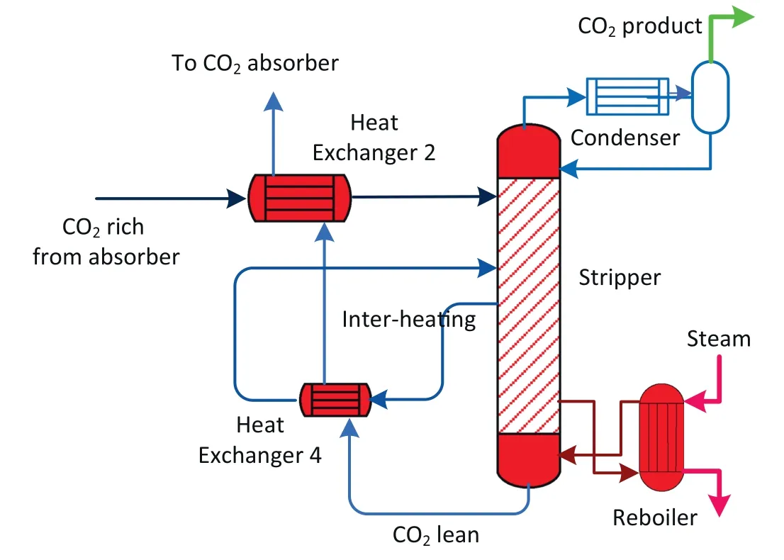
Fig.9.Schematic of inter-heated stripping process.

Both NH3and potassium carbonate can capture CO2.The unique feature of the mixed-salt solvent is that NH3can work as a promoter/catalyst for CO2capture,and potassium carbonate can help reduce NH3emissions in the absorber.Low NH3emissions enable the CO2absorption process to take place at ambient temperature,thus eliminating the chilling requirements and reducing cooling water consumption.The benefits are achieved through staged and recycled absorption and selective regeneration.The process flowsheet is shown in Fig.13.
The key feature of the mixed-salt CO2capture system is its two-stage absorber combined with a novel selective regenerator.Flue gas from the power plant first passes through the FGD unit and is cooled to 20–40°C before entering absorbers 1 and 2 in series.In absorber 1(first-stage absorption),an NH3-rich solvent is used to capture the majority of CO2(up to 80%).In absorber 2(second stage absorption),a potassium carbonate-rich solution is employed to recover the majority of NH3emitted and a relatively small percentage of CO2.The absorber operates with liquid recycle and cooling to keep the solution in the range of 20–40°C,thereby maintaining a relatively uniform temperature.
The regeneration process selectively produces two CO2-lean streams in response to the two streams used in absorber:an NH3-rich solution at the top and a potassium carbonate-rich solution at the bottom.In a typical operation,the CO2-rich solution with a total 38 wt%of NH3and potassium and CO2loading of up to 0.6 CO2/alkali molar ratio is introduced to the stripper top,and the regeneration is operated at an isobaric high pressure(1–4 MPa)but a varying temperature profile(60–70°C at the top and more than 120°C at the bottom).At the bottom of the stripper,potassium-rich solvent is produced and fed to the absorber top section.The high temperature at the bottom of the stripper drives evaporation of NH3,water and CO2.The NH3and water condense as the vapour rises and temperature drops,resulting in an NH3-rich solution in the middle section of the regenerator.This solution is then sent to absorber 1.
SRI International demonstrated the mixed-salt technology on a bench-scale facility and used the data obtained to develop a ratebased process model[40].Based on the model,a preliminary technoeconomic evaluation of mixed-salt technology was carried out for capture of 90%CO2from a 550-MW supercritical power plant in comparison with Fluor's Econamine FG PlusSMtechnology.The mixed-salt process has a calculated reboiler duty of 2.0 MJ per kg of CO2,much lower than of the Econamine FG PlusSMtechnology(3.56 MJ per kg of CO2).The calculated cost of electricity for the mixed-salt process is 127.3 USD·(MW·h)-1, more than 10% lower than both Fluor's Econamine FG PlusSMtechnology and Cansolv's amine process.

Fig.10.Predicted effect of inter-heating process on(a)temperature profile along the column and(b)distribution of three heat components:heat of CO2 desorption,heat of vaporisation and sensible heat.
2.4.Other developments
Several research groups have explored other options to improve aqueous NH3-based capture technologies[42–54].Some groups have used hollow-fibre membrane as the gas liquid contactor in aqueous NH3-based capture,aiming to reduce NH3loss in the absorption process[42–44].Liquid and gas flow in each side of the membrane contactor,and so do not contact directly.CO2from the gas side diffuses through the membrane pores to the liquid side.The advantages of the hollowfibre membrane contactor include:
(1)NH3loss can be controlled,since it needs to diffuse through the membrane pores before reaching the gas side.The pore size and membrane properties can be varied to control NH3evaporation to the gas side.
(2)The membrane contactor offers a much higher interfacial surface area than packed columns.
(3)The gas and liquid flows can be controlled separately.This can help avoid issues such as entrainment,flooding,channeling and foaming that occur in the packed column.

Fig.11.Mass transfer coefficient of CO2 in the mixture of NH3 with amino-acid salts as a function of CO2 loading at a temperature of 288 K.Reproduced from[36].
The results from these studies indicate that the membrane contactors can reduce NH3loss,but not eliminate it.The hollow-fibre membrane contactors are actually used for NH3recovery from water[55,56].This shows that gaseous NH3can also transfer through the membrane pores,causing NH3loss.In addition,membrane wetting occurred in aqueous NH3capture using a hollow-fibre membrane.Cui et al.investigated the absorption of CO2into aqueous NH3in a gas/liquid contactor fitted with hollow-fibre polytetrafluoroethylene membranes at ambient temperature. The absorption performance decreased gradually after 1 h of operation due to membrane wetting and fouling(formation of ammonium bicarbonate on the membrane surface).
Zhang et al.and Ullah et al.simulated a novel process for aqueous NH3-based CO2capture by integrating a flow-by capacitive ion separation device(CDI)[45,46].A CDI is an electrochemical purification system that uses charged electrodes to absorb and desorb ions in the solvent.By operating CDI in an adsorption and desorption cycle,the rich solvent can be split to ion-lean and ion-rich solutions.Only ionrich solutions will be sent to the stripper for regeneration.The process simulation indicated the stripper regeneration energy can be significantly reduced.
3.Future Research
CAPs have been well developed and trialled at scales of up to 100,000 t of CO2per year capture capacity.The next step is expected to demonstrate the technology at a commercial scale(more than 1 million tonnes per year).
With support from the Coal Innovation New South Wales fund,CSIRO will demonstrate the advanced technology described in Section 2.2 and its benefit using Delta Electricity's CO2capture pilot plant at Vales Point Power Station,NSW.The performance targets of the trials include:

Fig.12.Mass transfer coefficient of CO2 in the mixture of NH3 with piperazine(PZ)and its derivatives as a function of CO2 loading at a temperature of 288 K.Reproduced from[36].

Fig.13.Simplified diagram of SRI's mixed-salt technology.Reproduced from[41].
•achieving combined SO2and CO2removal percentages of more than 95%and 85%,respectively
•producing high purity of CO2(99 vol%–100 vol%)at elevated pressure
•reducing NH3slip in the exiting flue gas to acceptable levels that can match those achieved in the reference CAP,assuming the pilot plant can be operated under designed conditions
•reaching a CO2capture rate of 80–120 kg·h-1
•proving that the new stripper configuration can eliminate solid precipitation and reduce regeneration energy compared with the baseline operation
•reducing the thermal efficiency loss by 20%compared with reference MEA-based processes.
The successful completion of the pilot-plant trials will help lay a solid foundation for a larger-scale integration demonstration at a CO2capture capacity of more than 10000 t·a-1.
The integration trials allow a detailed evaluation of the interdependent relationship between the key components of the integrated process,including the power station,CO2capture unit and SO2removal unit.There is a significant knowledge gap in this area,and practical experience is also lacking for integration with Australian power stations.
SRI International's mixed-salt technology was tested at bench scale;the next step should involve pilot-scale trials to evaluate its potential.Many other developments in aqueous NH3-based PCC technologies,including the use of hollow-fibre membranes and capacitive ion separation,are still at early stage of the development.These approaches have already been applied to amine-based capture processes.Future research should therefore consider the unique properties and issues specific to aqueous NH3to advance the aqueous NH3-based capture technologies and make the technologies more competitive.
4.Conclusions
In this paper,we have reviewed recent advancements in aqueous NH3-based CO2capture technologies.Research efforts have mainly focused on GE's CAP, CSIRO's mild-temperature process and SRI International's mixed-salts technology.CAP has been assessed at bench,pilot and demonstration scales and is well developed.Field tests have demonstrated the chilled NH3process has a lower energy consumption and a lower NH3emission.CSIRO's mild-temperature process builds on the pilot-plant trials and incorporates several innovative features,including combined flue gas cooling,SO2and CO2capture and NH3recovery,staged CO2absorption,and stripper rich split and interheating.Preliminary techno-economic assessment has shown that the improvements could significantly reduce capture costs.SRI International has been developing a mixed-salt capture technology using a mixture of NH3and potassium carbonate.The process incorporates staged absorption and selective regeneration to reduce energy consumption and NH3loss in the capture process,and has a calculated reboiler duty of 2.0 MJ per kg of CO2.These three technologies need further research work to demonstrate their economic viability.Other early stage developments reviewed include hollow-fibre membranes and capacitive ion separation.To advance aqueous NH3-based capture technologies and make the technologies more competitive,more research is needed to make use of the unique properties of aqueous NH3and address its specific issues.
杂志排行

Chinese Journal of Chemical Engineering的其它文章
- Ni/bentonite catalysts prepared by solution combustion method for CO2 methanation☆
- Mass transfer correlations for membrane gas-solvent contactors undergoing carbon dioxide desorption
- Carbon deposition and catalytic deactivation during CO2 reforming of CH4 over Co/MgO catalyst☆
- The CO2 absorption and desorption performance of the triethylenetetramine+N,N-diethylethanolamine+H2O system☆
- Modelling of a post-combustion carbon dioxide capture absorber using potassium carbonate solvent in Aspen Custom Modeller
- High-efficiency and pollution-controlling in-situ gasification chemical looping combustion system by using CO2 instead of steam as gasification agent