LES Simulations of the Flow Around a Propeller in Crash Back and Crash Ahead
2018-03-28CHENJinZOUZaojian
CHEN Jin,ZOU Zao-jian,2,3
(1.School of Naval Architecture,Ocean and Civil Engineering,Shanghai Jiao Tong University,Shanghai 200240,China;2.Collaborative Innovation Center for Advanced Ship and Deep-Sea Exploration,Shanghai 200240,China;3.State Key Laboratory of Ocean Engineering,Shanghai Jiao Tong University,Shanghai 200240,China)
0 Introduction
Ships fitted with dynamic tracking or dynamic positioning systems need to maneuver under low speed conditions.Pilots need to know the maneuvering performance of the ships in the restricted water area,such as a narrow channel or a port.A ship may maneuver at low speed under these circumstances and it could move either headway or sternway while the propeller is thrusting ahead or astern.The propeller operates in four quadrants which are defined by the four combinations of ship speed directions with thrust directions.The schematic of propeller operation in four quadrants is illustrated in Fig.1.The four quadrants of propeller operation are defined as forward(ship ahead+V,propeller ahead+n),crash ahead(ship astern-V,propeller ahead+n),backing(ship astern-V,propeller astern-n),crash back(ship ahead+V,propeller astern-n),where V is the ship speed,n is the propeller rotational speed.The flow is quite complicated during crash ahead and crash back where the propeller wake interacts with the free stream flow.Side force occurs when the unsteady flow becomes dominant,which makes it difficult to control the ship’s trajectory.Highly fluctuation of the transient pressure leads to the vibration of the hull and the structural failure of the propeller.These considerations motivate the present study to access the hydrodynamic performance of a propeller operating in crash ahead and crash back.

Fig.1 Schematic of the propeller operation in four quadrants
The hydrodynamic performance of a propeller operating in four quadrants has been treated traditionally by experimental means.Oltmann and Sharma[1]conducted experimental research on a single-screw tanker and a twinscrew center-rudder container carrier,and proposed a maneuver model which is applicable to forward and backward motion,taking account of the hull-propeller-rudder interaction in four quadrants.Jiang et al[2]studied the flow structure under crash back and crash ahead using particle image velocimetry(PIV)measurements.Complex flow separation and unsteady vortex ring were found.They noted that the strength and location of the unsteady vortex ring were related to the unsteady shaft forces.Chesnakas et al[3]reported an experimental research on propeller 4381 operation in crash back and ahead condition in a 36-inch water tunnel.Bridges et al[4]and Donnelly et al[5]conducted experimental investigations of a submarine model during crash back in the same water channel.Unsteady forces and moments were measured on a ducted propeller under crash back condition.The unsteady rotor side forces were noted to be approximately 10%of the mean propeller thrust,while the total side force is approximately 30%of the rotor thrust.
The potential flow methods were widely used in propeller design for a propeller operating in forward condition.Hoshino[6]proposed a surface panel method for the analysis of steady and unsteady propeller flows.However,the potential flow methods are inadequate to predict the propeller flow during off design conditions.A propeller can operate in reverse motion under crash back.The free stream flow can impinge on the back side of the propeller under crash ahead.These flow phenomena are dominated by viscous effects.Computational Fluid Dynamics(CFD)methods can be employed for solving the unsteady,separated flows.Chen and Stern[7]solved the Reynolds-averaged Navier-Stokes(RANS)equations for propeller flow including forward,backing,crash ahead,and crash back conditions.They concluded that RANS yielded good results for forward and backing modes but produced significant discrepancies in crash back and crash ahead conditions.Complex flow pattern like turbulent wake,leading edge separation,marked velocity gradients,and unsteady ring vortices occurred while the propeller operated under crash ahead and crash back conditions.RANS methods failed to provide satisfactory results.Lee[8]employed a RANS method in conjunction with an overlapping moving grid to provide accurate solution of four quadrants propeller flows.He concluded that more accurate and robust numerical methods are needed in order to capture these unsteady effects induced by propeller operations under crash ahead and crash back conditions.Jang[9]and Jang et al[10]performed Large Eddy Simulation(LES)for a propulsor in crash back and validated against experimental data.A sliding interface method including search algorithm and interpolation scheme for arbitrary shaped unstructured grids on parallel computing platforms was developed.They found that both thrust and sideforce were seen to be mainly generated from the leading edge of the suction side of the propeller.The vortex ring core was closer to the propeller blades during high amplitude events.Verma et al[11-12]performed LES for a propeller with and without a hull at two advance ratios.It showed that the presence of an upstream hull significantly increased the side force on a propeller in crash back.A recirculation zone upstream in the vicinity of the propeller was formed and a vortex ring remained much closer to the propeller at high advance ratio.Sileo et al[13]presented the results of CFD simulations of the flow past a marine propeller.Computational results were obtained for all the four quadrants operational conditions,considering non-positive values for the advance ratio.
In the present study,CFD simulations of the flow around the propeller DTMB 4381 under crash back and crash ahead conditions are performed and the LES is applied.Grid dependency study in crash back is carried out.The simulation results of forces and moments are compared with the available experimental data provided by Chesnakas et al[3].The effect of advance ratio is investigated.Flow details like pressure contours on the blades,velocity distribution at the axial planes with typical streamlines are used to analyze the underlying physical mechanism.
1 Mathematical formulation and numerical method
1.1 Governing equations
The governing equations for the viscous flow around the propeller are the following continuity equation and unsteady RANS equations:

where xiis the ith component of the coordinate system,uiand ujare the mean velocity component,p is the mean pressure,μ is the viscosity coefficient,ρ is the density of water,the Reynolds stress.
1.2 LES
The direction of propeller wake and the free stream flow are opposite in crash back and crash ahead.The main difficulties of predicting the propeller performance lie in the modeling of the separation flow.The interaction between two opposing streams is characterized by largescale flow unsteadiness and separation.LES method is employed to determine the hydrodynamic characteristics under these circumstances.Chen and Stern[7]concluded that RANS yielded good results for forward and backing conditions,but produced significant discrepancies up to 110%in crash back and crash ahead conditions.The computed results demonstrated 3%oscillation about the mean value while the experiment showed 20%.RANS simulation is deficient in predicting the tangential velocity field.The time averaging employed by RANS neglects the turbulent fluctuations.It is believed that LES could provide more accurate solutions than RANS simulation in resolving the large-scale unsteady turbulent flow.However,LES costs more computational time and resources compared to RANS.
In LES,each flow variable is decomposed into a large-scale component and a sub grid scale component where the large-scale component is obtained by applying a moving-filter operation.The subgrid scale models generally contain fewer empirical coefficients and artificial factors than those used in the turbulence models of RANS simulation.The governing continuity and momentum equations using filtered variables are as follows:

The sub grid stress τijis defined asWhen the grid size is sufficiently small,the impact from the sub grid scale models on the flow will be small.Small-scale motions,with sizes smaller than the grid size,are removed and are modeled by the sub grid scale(SGS)model[14].Larger eddies are directly solved numerically by the filtered transient N-S equation.SGS Reynolds stresses are modeled by:

where μtis the sub grid scale eddy viscosity,Sijis the rate of strain tensor.
1.3 Numerical solution
Simulations are performed by using the CFD code ANSYS-FLUENT.The solver employs a point implicit Gauss-Seidel method to solve the linear system of equations in conjunction with the algebraic multi-grid method.A second-order central discretization scheme is used for the spatial differencing,and a second-order central differencing for the viscous terms.The SIMPLE segregated algorithm is adopted to calculate the pressure field and to couple it to the velocity field.Meshes are generated by using the meshing program Gambit and T-grid.Sliding Mesh(SM)is employed for the rotation of the propeller,and is the most physically complete approach.Unsteady calculations are performed,where the grids surrounding the propeller move arbitrarily following the movement of the interface boundaries.
1.4 Computational domain and boundary conditions
The computational domain is chosen with a cylinder surrounding the propeller and aligned with the hub axis.The propeller axis is aligned with the z-axis of the coordinate system,located on the central of the domain,with the xaxis directing upward and the y-axis following the right hand rule.The computational domain with the coordinate system is shown in Fig.2.The computational domain is defined by propeller diameter D.The left and right boundary is located 6.5D from the center of the propeller.The diameter of the cylinder is 8D.The cylinder is divided into a dynamic cylindrical part and a static part.The dynamic part surrounding the propeller is about 1.0D in length with a diameter of 1.2D.It rotates together with the propeller with the same rotational speed,and is placed at the center of the domain.Information is transferred between the dynamic part and the static one through the interface boundary condition.The free stream velocity is specified at the inlet and the circumferential boundary of the cylinder.The no-slip wall condition is imposed on the surfaces of the propeller blades and the hub.The rotational direction of the propeller and the boundary conditions on the both sides are listed in Tab.1.

Fig.2 Computational domain

Tab.1 The rotational direction of the propeller and the boundary conditions
2 Case for study
The model of propeller DTMB 4381,a right-handed propeller with variable pitch,no skew and no rake,is selected for the simulation.The propeller geometry is shown in Fig.3.The propeller parameters are listed in Tab.2.Jang et al[10]performed LES for this propeller in crash back for various advance ratios and validated against experimental data.Verma et al[11]employed LES to simulate the flow over the propeller with or without a hull at two advance ratios.
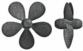
Fig.3 DTMB 4381 geometry
The Gambit is used for grid generation.The T-grid is employed to generate prismatic cells to resolve the flow in boundary layers around the blades.The surfaces on the hub and blades have been triangulated.Ten layers of prismatic cells have been attached to the blades.The first grid point away from blades and hub is placed at a distance 0.000 6D.A small cylinder domain which wraps the propeller is generated.The size of the small domain should be as small as possible since tetrahedral grids increase the overall mesh size and have poorer accuracy.The remaining region of the small dynamic part has been filled with tetrahedral cells.Hexahedral elements are used outside the small domain.The grid is coarse towards the left and right boundaries and is clustered around the blades in the circumferential and longitudinal directions for the resolution of typical flow features like the propeller wake and the vortex ring.Grids around the blade surface are shown in Fig.4(a).Grids on the slice plane at Z=0 are shown in Fig.4(b).

Tab.2 Geometric parameters of DTMB 4381 model

Fig.4 Grid around the blade(a),and at the plane Z=0(b)
3 Numerical results and discussions
The forces and moments acting on the propeller are obtained.Thrust TZis the axial component of the force,torque QZis the axial component of the moment,and side force Tyis the horizontal component of the force.Non-dimensional thrust coefficient KTz,torque coefficient KQzand side force coefficient KTyare defined as follows:

where nD is used as the characteristic reference velocity.
3.1 Grid dependency study in crash back
Grid dependency study is carried out when LES is employed under crash back.LES results depend heavily on various factors including the grid,the numerical method employed and the boundary conditions.The basic principle of LES is to resolve all large eddies,while the dissipative small eddies are modeled by SGS models.Geurts and Frohlich[15]concluded that grid resolution affects not only the numerical discretization error but also the sub grid scale model contribution.The transfer of momentum caused by turbulent eddies is modeled with turbulent viscosity.In the present simulations,Smagorinsky sub grid model is used to represent the turbulent viscosity.It assumes that an equilibrium exists between the kinetic energy flux across scale and the large scales of turbulence[16].
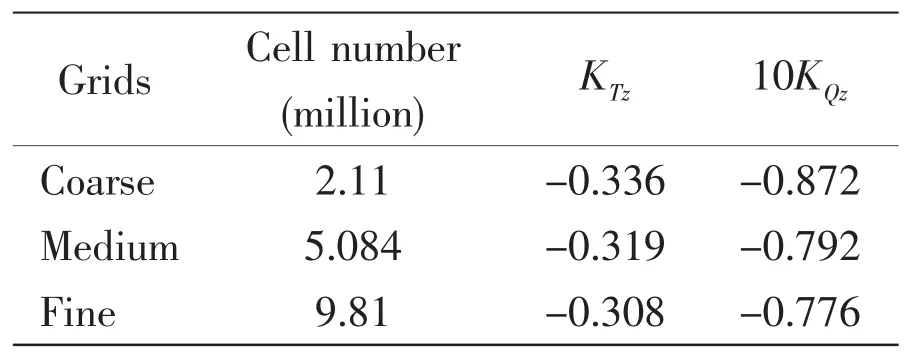
Tab.3 Resultsof grid independence study
Results of grid independence study are summarized in Tab.3 in terms of the number of cells,KTzand KQz.The meshes are refined on the blades and in the regions adjacent to the blades.The absolute values of KTzand KQzdecrease with the increasing grid numbers.The relative difference of KTzand KQzbetween the medium and fine grids is 3.9%and 2.11%.Fig.5 shows the contours of axial velocity at the plane x=0,(a)for coarse grids and(b)for fine grids.Similar trends are observed,the regions with accelerated flows are closer to the blades for finer grids.Fig.6 shows the contours of sub grid turbulent viscosity ratio at the plane x=0 under coarse grids and fine grids.It reveals that the fluctuating sub grid kinetic energy is dependent on the grid resolution.The turbulent viscosity ratio reaches a higher level for finer grids,and the fluctuating turbulent flow is more pronounced.It can be concluded that mean quantities become rapidly grid independent while resolved fluctuating quantities more pronounced for higher grid resolutions.
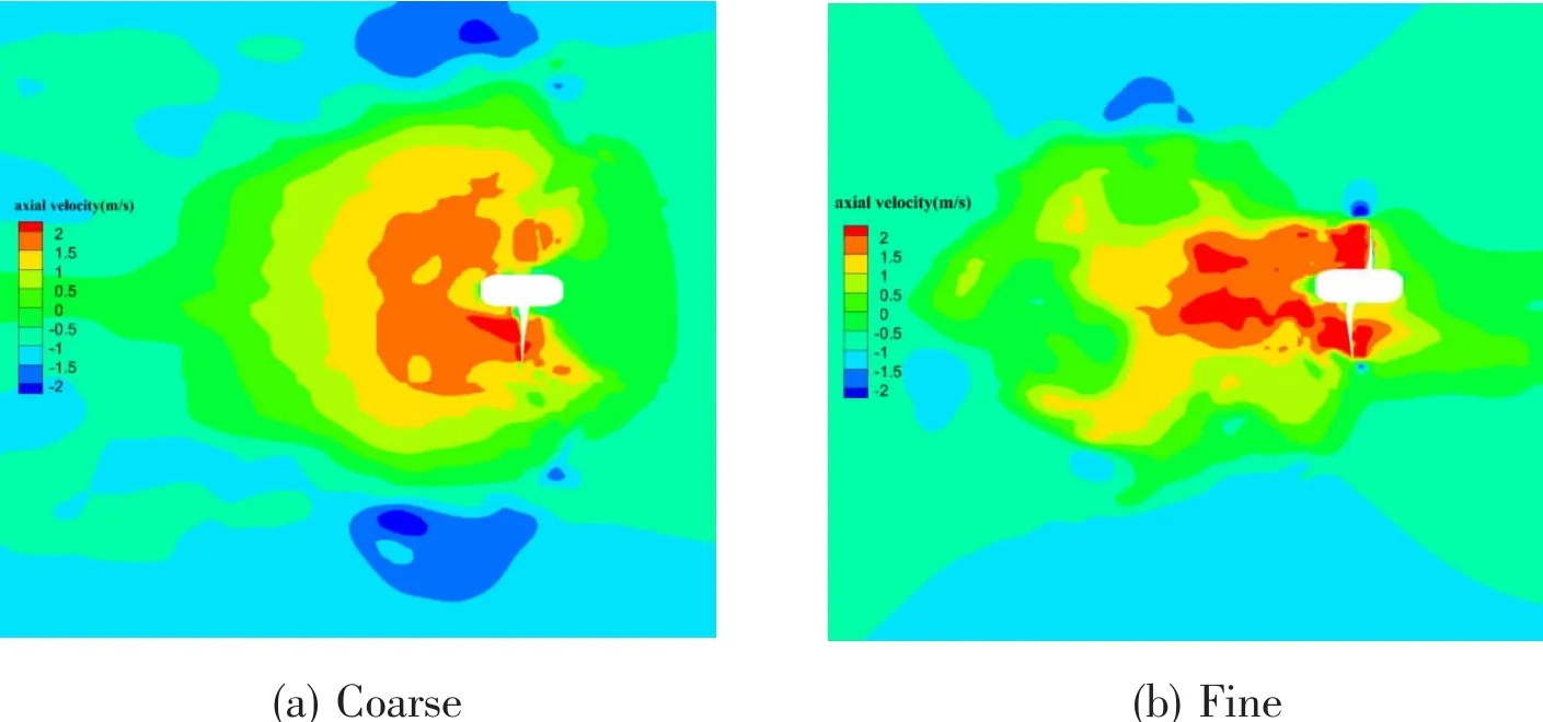
Fig.5 The contours of axial velocity at the plane x=0
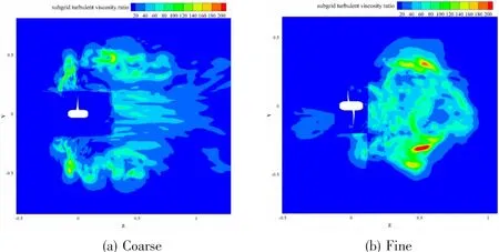
Fig.6 The contours of sub grid turbulent viscosity ratio at the plane x=0
3.2 Crash ahead
During crash ahead,the vessel moves in the backward direction while the propeller pushes the vessel forward.The propeller wake counteracts with the free stream flow coming from the stern.The speed of the vessel is gradually reduced.The propeller flow under several combinations of n and V is investigated.
LES method is applied for resolution of highly separated flows occurring in crash ahead.The computational mesh consists of 5.06M cells.A steady RANS simulation based on the SST k-ω turbulent model has been performed to provide the initial average flow field for LES.Then the unsteady LES is carried out.The time step is set depending on n,corresponding to 2°of propeller rotation.Uniform inflow is assumed at the inlet and Re=3.05×10⁵,where Re denotes the Reynolds number which is defined asIn order to analyze the effect of the loading condition on the propeller performance,three different advance ratios J=-are considered.The advance ratio is obtained through varying the rotational speed of the propeller at a constant V.
Instantaneous pressure contours on the face and back sides at J=-0.2 and-1.2 are shown in Fig.7(a),Fig.7(b),respectively.Cp is non-dimensionalized usingpressure occurs at the face side,relative lower pressure occurs at the back side.A very high pressure gradient is observed at the trailing edges under crash ahead.This phenomenon is related to the interaction between the propeller wake and the free stream flow.

Fig.7 Pressure contours on the blades under crash ahead
To understand the physical mechanism during crash ahead,axial velocity distribution with typical streamlines at J=-0.2 and-1.2 is shown in Fig.8.The free stream flow points to z direction while the propeller rotation sucks the flow to the negative z direction.Two large counter rotating zones are generated by the interaction between the free stream and the flow sucked by the propeller rotation.The recirculation zone is centered symmetrically at the upper and the lower halves,where the axial velocity is zero.A clockwise vortex on the upper half and an anticlockwise vortex on the lower half form.
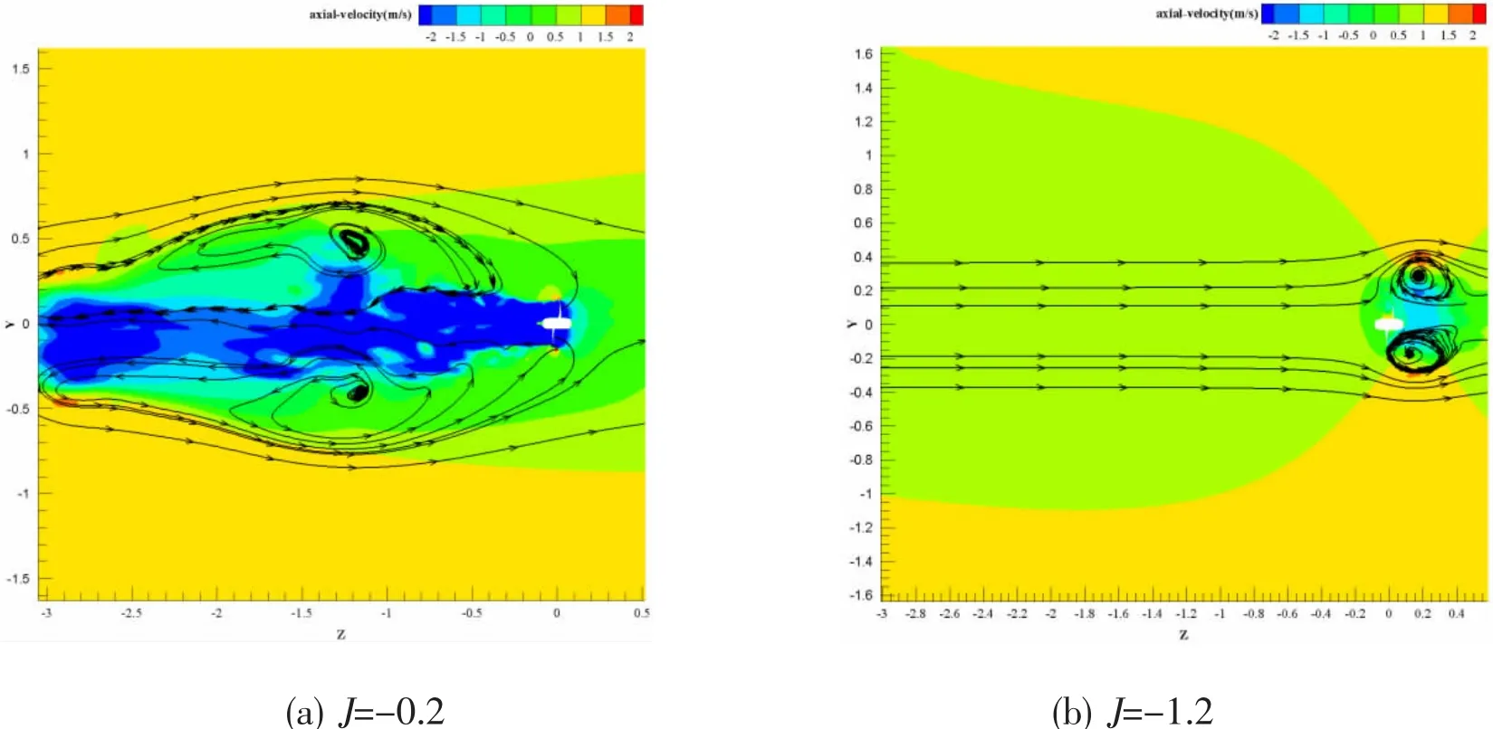
Fig.8 Transient axial velocity contours with streamlines
It should be noted that the location and size of the recirculation zone are dependent on operating J.At J=-0.2,the recirculation zones are located symmetrically at the upstream of the propeller,and the positions of the core are(y,z)=(±0.5,-1.2)which is far from the centerline.However,these zones are located symmetrically at the downstream of the propeller at J=-1.2,and its center is located at(y,z)=(±0.3,0.25)and is closer to the blade tip.It can be concluded that the propeller wake plays a dominant role over the free stream flow at lower J condition(absolute value),where a strong reverse flow is produced.
In order to investigate the influence of advance ratio on the separation characteristics,the topology of the wake for a high J and a low J is described.Axial velocity contours on several planes are shown to provide detailed information on the wake of the propeller.Four transverse planes,z=0,0.15,0.23 and 0.3,are used to track the propeller wake as it propagates downstream for J=-1.2.Fig.9 shows the contours of axial velocity on these planes.The strongest acceleration in circumferential position is observed at the section z=0.15.The regions with highest velocity in z direction stretch from z=0.05 to z=0.2.This should be expected as the outcome of the vortex ring in the circumferential position.
The fluctuation of KTzand its corresponding spectral characteristics at J=-0.2 under crash ahead are shown in Fig.10.Spectral characteristics are extracted from the data of time histories using a fast Fourier transform(FFT)algorithm.Relative regular fluctuation of KTzis observed due to periodicity of the flow in fully developed state.The average value of KTis 0.571.The complex recirculation areas could make the flow unstable and cause the fluctuation of the propeller thrust.Spectral characteristics of KTzdemonstrate peaks at 86 Hz,108 Hz and 216 Hz.It is observed that the amplitude around 108 Hz is the most significant,which is the blade passage frequency(BPF)of the five-bladed propeller.The frequency that is above 250 Hz can be negligible.The frequency of the vortex ring shedding due to the complex recirculation flow is around 86 Hz.The blade periodic flow due to propeller rotation is more remarkable than the effect of the vortex ring.
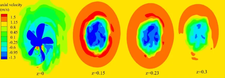
Fig.9 The axial velocity at several transverse sections of the downstream wake of the propeller at J=-1.2

Fig.10 The time history of KTzand its corresponding amplitude spectrumat J=-0.2
Fig.11 shows the comparison between the simulation results and experimental data[3]under different J in crash ahead condition.The computed KTzis in good agreement with the corresponding experimental data.Relative large discrepancy exists in KQz,where the maximum deviation of KQzis 14.78%occurred at J=-0.7.The validity of present LES method is achieved.Side force coefficient KTyincreases as J decreases.
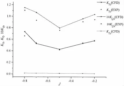
Fig.11 Comparison between the computed results and experimental data
3.3 Crash back
During crash back,the propeller moves in the forward direction while the propeller rotates in the reverse direction.The free steam velocity is-1 m/s.Different advance ratio is achieved by varying the rotational speed n.To obtain the average flow field,a steady solution of RANS simulation based on the SST k-ω turbulent model has been obtained.With this known steady flow field as the initial condition,an unsteady LES simulation has been performed.The target residuals were set at 10-4and the maximum iteration number per time step was 20.Calculations are performed for 2 000 iterations first when the time step was set corresponding to 360°of propeller rotation.Then the time step is reduced corresponding to 2°of propeller rotation.The forces and moments are averaged over the last 20 propeller revolutions.
The pressure distributions on the face and back side sunder crash back at J=-0.2 and J=-0.5 are plotted in Fig.12.The leading and trailing edges of propeller blades exchange its roles due to the reversal of the propeller.High pressure occurs on the back side and low pressure on the face side.The thinner edges of the blades act as the leading edge and the thicker edges act as the trailing edge.High pressure gradient around the sharper leading edge of the back side is observed.The pressure on the blades is in general quite irregular at J=-0.5,and is quite smooth at J=-0.2.This phenomenon is associated with the location of the recirculation zone.
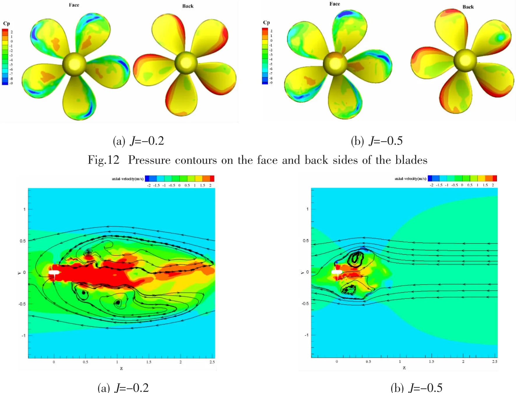
Fig.13 Axial velocity contours with streamlines
The distributions of axial velocity with typical streamlines on the plane x=0 at J=-0.2 and J=-0.5 are shown in Fig.13.The free stream is toward the negative z direction.The reverse fluid is sucked towards z direction due to the reverse rotation of the propeller.The recirculation zones around the blades are formed in the shape of a ring vortex caused by the interaction between the free stream flow and the reverse flow.The recirculation zone is located upstream of the propeller with higher axial velocity at J=-0.2,and is located downstream at J=-0.5.At J=-0.5,the downstream recirculation zone appears to be smaller and its center is closer to the blades due to the weaker reverse flow,resulting in smaller pressure difference and lower KTz.Lower advance ratio corresponds to the higher rotational speed of the propeller.It can be concluded that the effect of the propeller wake on the flow is dominant at higher J.The recirculation zone locates closer to the tip of the blades at J=-0.5 in comparison to J=-0.2.The location of the vortex ring affects the pressure difference on the blades.The pressure difference reaches its lowest value at J=-0.5 when the center of the vortex ring is located around the tip of the blade.
The time history of KTzand its corresponding spectral characteristics for J=-0.2 and J=-0.5 under crash back are shown in Fig.14.The data scatter appears to be slightly higher than that in the crash ahead cases.The standard deviation is used to describe the variation in loads relative to the mean value.The standard deviation(0.016)at J=-0.2 in crash back is significantly higher than that in the corresponding crash ahead condition(0.001 7).It indicates that the flow is highly unsteady in crash back.The data scatter is less for J=-0.5 with the standard deviation of 0.004 6.The flow becomes smooth with decreasing J.As is shown by the spectral response curves of J=-0.2 in Fig.14,two main peaks are concentrated in lower frequency region than the blade passage frequency,and have higher amplitude.It is caused by the periodic shedding of the ring vortex.
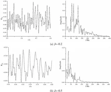
Fig.14 The time history of KTzand its corresponding spectral characteristics
The comparison between the calculated results and the experimental data under crash back is shown in Fig.15.The predicted KTzshows a good agreement with the experimental data.Relatively large discrepancy of KQzis 12.7%occurred at J=-0.3.The side force KTyis about an order of magnitude smaller than KT,and has a slight downward trend with increasing advance ratio.In Chesnakas’s experimental research[3],large areas of cavitation bubbles occur at the blade leading edge on the downstream side,which are dissipated by the unsteady recirculation region.Cavitation is not accounted for in the present simulations.This may cause large discrepancy.

Fig.15 Comparison between the LES results and experimental data
4 Conclusions
The unsteady separated flow over a propeller under crash ahead and crash back is investigated by using Large Eddy Simulation in non-cavitating condition.The calculated results of KTzand KQzshow reasonable agreement with experimental data for crash ahead,the recirculation region is located downstream of the propeller at J=-1.2 and is located upstream at J=-0.2.The propeller wake plays a dominant role over the free stream flow at lower J condition(absolute value).The blade passage frequency of the five-bladed propeller is the most significant at J=-0.2.The blade periodic flow due to propeller rotation shows dominant effect over the vortex ring.
LES simulations yield satisfactory results compared to experimental data under crash back.The location of the recirculation zone affects the pressure distribution on the face and back sides.The recirculation zone appears to be smaller and its center is closer to the blades at lower J condition.The flow is highly unsteady in crash back in comparison to crash ahead under the same J.The flow becomes smooth with decreasing J during crash back.The side force has a slight downward trend with increasing J.The frequencies of the oscillation of the ring vortex are concentrated in lower value than the blade passage frequency.
The presented method is adequate for predicting the flow over a propeller in crash ahead and crash back.Further improvements may be emphasis on the mesh technique and cavitation.The automatic dynamic mesh technique may be needed to resolve the wake of a rotating propeller during a revolution.Cavitation modeling needs to be taken into account in the future simulations.
Acknowledgements
This work is financially supported by the National Natural Science Foundation of China(Grant Nos:51279106,51779140).
[1]OltmannP,Sharma S D.Simulation of combined engine and rudder manoeuvres using an improved model of hull-propeller-rudder interactions[C]//Proc.Of 15th Symposium on Naval Hydrodynamics.Washington,DC,USA,1984:83-108.
[2]Jiang C W,Dong R R,Liu H L,et al.24-inch water tunnel flow field measurements during propeller crash back[C]//Proc.of 21th Symposium on Naval Hydrodynamics.Trondheim,Norway,1996:136-146.
[3]Chesnakas C J,Donnelly M J,Fry D J,et al.Performance of propeller 4381 in crashback[R].Hydromechanics Department Report,Naval Surface Warfare Center Carderock Division,2004.
[4]Bridges D H,Donnelly M J,Park T J.Experimental investigation of the submarine crashback maneuver[J].Journal of Fluids Engineering,2008,130(1):011-103.
[5]Donnelly M J,Jessup S,Etebari A.Measurement of steady and unsteady duct loads for propeller 4381 at crashback conditions in the 36’water tunnel[R].Hydromechanics Department Report,Naval Surface Warfare Center,2010.
[6]Hoshino T.Hydrodynamic analysis of propellers in unsteady flow using a surface panel method[J].Journal of the Society of Naval Architects of Japan,1993,174:71-87.
[7]Chen H,Stern F.Computational fluid dynamics of four-quadrant marine propulsor flow[J].Journal of Ship Research,1999,43(4):218-228.
[8]Lee S K.CFD simulation for propeller four-quadrant flows[R].ABS Technical Papers,2006.
[9]Jang H.Large eddy simulation of crashback in marine propulsors[D].Minnesota:University of Minnesota,2011.
[10]Jang H,Verma A,Mahesh K.Predicting unsteady loads in marine propulsor crashback using large eddy simulation[J].International Journal of Rotating Machinery,Article ID 543096,2012.
[11]Verma A,Jang H,Mahesh K.The effect of an upstream hull on a propeller inreverse rotation[J].Journal of Fluid Mech,2012,704:61-88.
[12]Verma A,Jang H,Mahesh K.Large eddy simulation of the effect of hull on marine propulsors in crashback[C]//Proc of the 2nd International Symposium on Marine Propulsors.Hamburg,Germany,2011.
[13]Sileo L,Aldo B,Vinicio M.RANS simulation of the flow past a marine propeller under design and off-design conditions[C]//Proc.of 4th Annual Conference of the Computational Fluid Dynamics Society of Canada.Canada,2006.
[14]Celik I B,Cehreli Z N,Yavuz I.Index of resolution quality for large eddy simulations[J].Journal of Fluids Engineering,2005,127(5):949-958.
[15]Geurts B J,Fröhlich J.A framework for predicting accuracy limitations in large-eddy simulations[J].Physics of Fluids,2002,14(6):41-L44.
[16]Gaitonde U,Laurence D,Revell A.Quality criteria for large eddy simulation[D].Manchester:University of Manchester,2006.
杂志排行
船舶力学的其它文章
- Numerical Study of the Shapes of the Super-Rogue Waves
- Hydroelasitic Analysis of the Gravity Cage Subjected to Irregular Waves and Current
- Application of Propagation Characteristics of Translating-Pulsating Source Green Function in the Side-Wall Effects Discrimination
- Study on Vulnerability Criteria and Model Experiment for Surf-Riding/Broaching
- Investigations on the Mechanical Behavior of an Innovative Subsurface Tension Leg Platform in Ultra-Deep Water(Part I)
- Low-Cycle Fatigue Crack-Propagation Behavior of Ship Cracked Plate Considering the Accumulative Plasticity under Variable Amplitude Loading
