Roughness evaluation in shotcrete-lined water tunnels with invert concrete based on cases from Nepal
2018-03-01ChhatraBahadurBasnetKrishnaKantaPanthi
Chhatra Bahadur Basnet,Krishna Kanta Panthi
Department of Geosciences and Petroleum,Norwegian University of Science and Technology,Sem Saelands Vei 1,NO-7491,Trondheim,Norway
1.Introduction
The waterway tunnels represent the most significant source of construction cost for hydropower projects,especially for run-of the-river plants.Reducing and optimizing the cost of waterway systems is therefore a major issue to make hydropower projects financially attractive.One of the economic solutions is to use unlined or shotcrete-lined pressuretunnels orcombination of both for the waterway system if the rock mass and applied shotcrete and/or systematic bolting guarantee long-term stability and safety(Panthi,2015).Originally,the application of unlined shafts and tunnels as waterway systems came in practice in Norway with the philosophy that accepts minor falls of rock blocks during the operation period provided that head loss is within permissible limits(Broch,1982).The basic criteria to be satisfied for unlined or shotcrete-lined pressure shafts and tunnels are safety against hydraulic splitting,hydraulic efficiency(frictional head loss)and long-term stability(Brekke and Ripley,1987;Benson,1989).Frictional head loss depends on both cross-sectional area and roughness of tunnel periphery in consideration(Rahm,1958),because rougher tunnel wall surfaces will result in higher head loss and larger cross-sectional areas result in smaller head loss.An alternative way to reduce the head loss can be the use of concrete or steel lining to make the tunnel surfaces smoother without increasing tunnel size.However,lining a tunnel with concrete or steel will demand considerable additional cost(Huval,1969;Westfall,1996).
Tunnel shape also influences hydraulic efficiency of the water tunnel.In tunnel boring machine(TBM)tunneling,the tunnel cross-section is circular(i.e.hydraulically ideal shape)with smooth rock surfaces.However,it is not always feasible to use TBM as an excavation method since the success of TBM application is largely dependent on the geological conditions and length of the tunnel to be excavated.Hence,the drill-and-blast method of tunnel excavation is popular and extensively used due to flexibility in making decisions if unforeseen geological conditions arise and it can be used in any length of tunnel to be excavated,provided that ventilation requirements during construction are met.However,tunnel walls excavated using drill-and-blast method have an undulating surface of varying smoothness and the shape of tunnel will be determined mostly by construction necessities and easiness(Lysne et al.,2003).The most practical tunnel shapes in drill-and-blast tunneling are inverted D and horse-shoe(Cuesta,1988;Panthi,2015).In waterway tunnels,excavated tunnel profiles may either be left unlined or shotcrete-lined or concrete/steel-lined(or a combination of different linings).The shotcrete-lined tunnels end up more or less with the excavated shape and surface as shown in Fig.1.
As seen in Fig.1,there are undulations in the contour surface in a tunnel excavated using the drill-and-blast method due to the presence of grooves and projections.The frequency distribution and amplitude of these undulations signify resistance to water flow and are defined by the term surface/physical roughness.These undulations are the result of over-break of the rock mass beyond the designed tunnel profile(Maerz et al.,1996).The larger the overbreak area is,the more the tunnel surface will be undulated and rough.Hence,over-break is the key parameter to define roughness of the tunnel surface.According tovarious researches,over-break in drill-and-blast tunnels is the result of look-out and deviation in contour holes,blasting energy,rock mass condition and in situ stress situation(Nilsen and Thidemann,1993;Mandal and Singh,2009;Kim and Bruland,2015).Longer blast rounds develop greater longitudinal over-break leading to an increase in roughness of the tunnel surface.Similarly,the rock mass condition influences over-break intensity and roughness.In Fig.2a,the blasted tunnel surface is relatively smooth in the case of a homogeneous rock mass,whereas,if rock mass is jointed,the surface roughness is partially determined by the jointing pattern(Fig.2b).In addition,there might be some localized enlarged over-break due to the presence of faults or weakness zones(Figs.1b and 2c),which will further increase the roughness.Fig.2a is seldom achieved in the jointed rock mass,thus Fig.2b and c represents the most common contour profile types in blasted tunnels.Over-break in Fig.2a and b may be defined as normal over-break,whereas localized enlarged area in Fig.2c may be expressed as excessive over-break.Such localized enlarged areas may also be formed due to stress induced rock spalling and bursting in hard rock(Panthi,2012).
Now the question arises as how the physical roughness can be used to calculate frictional head loss along the waterway tunnel.Both the Darcy-Weisbach and Manning formulae use coefficient of resistance,known as hydraulic roughness,in order to calculate frictional head loss.However,the hydraulic roughness in the equations is not equivalent to the physical roughness directly measured from the tunnel surface.Before 1980,according to Bishwakarma(2012),it was a common practice to calculate hydraulic roughness from the relative variation of cross-sectional area along the tunnel length using different methods proposed by Rahm(1958),Priha(1969),Reinius (1970),Wright(1971)and others.Later in the 1990s,the concept was updated with the introduction of physical roughness of the tunnel,which is related to both surface undulations and are a variation(Bruland and Solvik,1987;Ronn and Skog,1997),and the physical roughness was converted to the hydraulic roughness in order to fit into the head loss equations.It is a common practice to calculate hydraulic roughness using the relationship proposed by Colebrook(1958)considering physical roughness as equivalent sand roughness.Bruland and Solvik(1987)extended their research and proposed a new relationship between physical roughness and hydraulic roughness where the physical roughness in their definition does not correspond to the sand roughness.On the other hand,the total physical roughness defined by Ronn and Skog(1997)corresponds to the sand roughness and fits into Colebrook(1958)’s equation.More recently,attempts have also been made to relate measured physical roughness to hydraulic roughness for bored tunnels(Pegram and Pennington,1998;Hákonardóttir et al.,2009).Regardless of the type of method used,a correct definition of physical roughness and its relation with hydraulic roughness are the key issues to define unlined or shotcrete-lined tunnel hydraulics.
Existing methods of estimating tunnel roughness are used only after the tunnel is excavated and the geometrical data of actual tunnel surface are available.In parallel to these methods,attempts have also been made to predict tunnel roughness before tunnel excavation based on over-break in tunnels(Colebrook,1958;Huval,1969;Priha,1969;Kim,2009),even though it is difficult to define over-break intensity and its relation to physical roughness.In this perspective,this article attempts to establish a new relationship between physical roughness and over-break thickness by analyzing actual tunnel profiles of the shotcrete-lined headrace tunnel of the Chilime hydropower project(CHP)in Nepal.Similarly,the article also attempts to establish a correlation between physical roughness and the Manning coefficient(hydraulic roughness)and proposes modifications on the methods proposed by Colebrook(1958)and Solvik(1984).Furthermore,the modified equations are used to predict roughness and hence the head loss and results are compared with the head loss measured at both headrace tunnels of the CHP and Modi Khola hydropower project(MKHP),respectively.
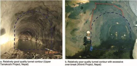
Fig.1.Tunnel contour quality after blasting and shotcreting.
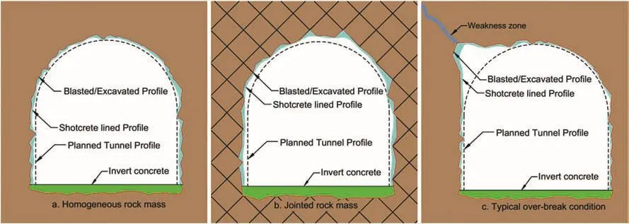
Fig.2.Quality of tunnel contour in different geological conditions.
2.Relevant theory
In the waterway system of hydropower projects,part of the potential energy is lost while transferring water from the headwater system to the powerhouse.There are mainly two reasons for this energy loss.First,the flowing water experiences resistance from the surface in which it flows due to a boundary layer developed in the interface of fluid and flow surface.The boundary layer is essentially formed due to viscosity of the fluid and condition of the surface.An energy loss is then produced by shear stress along the said boundary layer,which is called friction loss(Hager,2010).In addition,a part of energy is also lost as a singular loss,due to obstructions to the flow from different essential structural components built across the waterway system.Hence,the total energy loss,i.e.total head loss(H1),in the waterway system consists of two components:

whereHfis the frictional head loss andHsis the singular loss.The frictional head loss depends on flow surface condition and length of waterway system.On the other hand,singular loss typically consists of entrance loss,loss due to changes in cross-sections in the direction of flow,bend loss,exit loss and losses due to local disturbances caused by gates,trash racks,niches,rock traps,etc.
2.1.Roughness and frictional head loss
The flow surface of a waterway system is typically made up of different materials,such as gravel,concrete,rock,steel,and plastic.The resistance to flow is more pronounced in rough surfaces which have large undulations such as unlined or shotcrete-lined tunnel surfaces.The extent of undulations(protrusions and grooves)which has resistance to water flow can be expressed as the term roughness.Because of the spatial variation of these undulations along the surface,the roughness shall be generalized as equivalent roughness and is denoted as ‘ε’in this article.Since ‘ε’represents physical undulations of the surface,it is considered as physical roughness in the case of unlined or shotcrete-lined tunnel surfaces.However,the frictional head loss is calculated considering a coefficient of resistance called hydraulic roughness(forM),which depends upon physical roughness and/or hydraulic radius.It is important to note here that the friction factor(f)and the Manning coefficient(M)are hydraulic roughness,‘ε’in steel and concrete is equivalent sand roughness and ‘ε’in an unlined or shotcrete-lined tunnel is physical roughness that corresponds with equivalent sand roughness.Hence,in this article,the term roughness in general refers to all of the mentioned roughnesses.
As summarized in Table 1,the Darcy-Weisbach formula(Eq.(2))is used to calculate frictional head loss in any pressurized waterway.While using Eq.(2),the friction factor(f)is calculated by using different formulae for different flow conditions.According to Colebrook(1958),Eq.(3)can be used to calculate friction factor for the pipe flow when the Reynold’s number isR2300,whereas Eq.(4)is used in case of flow in rough pipesis the hydraulic radius).Alternatively,equivalent sand roughness of steel pipes and concrete conduits can be back-calculated by using Eqs.(2)and(3)if the frictional head loss is known beforehand.Colebrook(1958)also emphasized that unlined or shotcrete-lined tunnel hydraulics can be represented by the flow in hydraulically rough pipes.On the other hand,the Manning formula(Eq.(5))is mainly used in unlined or shotcrete-lined tunnels due to its simplicity where the Manning coefficient can be calculated by using different relationships such as Eq.(6).If carefully used,the Manning formula shows a good correlation with the Darcy-Weisbach formula,but this applies only for a specific range of applications according to Solvik(1984).Following the study of Colebrook(1958),Solvik(1984)developed Eq.(7)giving an application range of the Manning formula for frictional head loss calculation based on the inverse of relative roughness(4Rh/ε)of the closed conduit.
2.2.Singular losses
Different types of singular losses across the waterway system of hydropower projects are caused by entrance loss,trash rack loss,gate loss,bend loss,transition loss,niche loss,rock trap loss,exit loss and other similar factors.Table 2 shows all the equations that are relevant to calculating these singular losses.Each of these losses can be expressed as the function of velocity head and the coefficient ξ as defined by Eq.(8),where ξiis the head loss coefficient for a particular singular loss andviis the velocity of flow at the location considered.The total singular loss in whole waterway system is the sum of total number(n)of singular losses presented in the system(Eq.(9)).
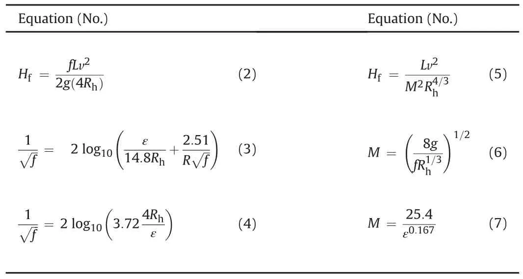
Table 1List of equations for the calculation of friction loss and roughness.
For entrance and exit losses,the coefficients(ξ1and ξ2)will be equal to 0.4-0.5 and 1,respectively(Lysne et al.,2003).Similarly,the coefficient of loss due to trash rack can be calculated using Eq.(10)suggested by Penche(2004).The typical arrangement of trash rack and rack types that are being used at the inlet and other locations of the water way system and their respective coefficients are shown in Fig.3 for the readers’reference.
In addition,there will be head loss at the gate location due to the presence of gate slots.The gate loss coefficient can be calculated using the relationship given by Hager(2010)for slide gates.The discharge coefficient(Cd)and the head loss coefficient(ξ4)of thegate with flat edge(i.e.edge roundingrvis zero)can be calculated using Eqs.(11)and(12),respectively,whereØis the relative opening of the gate as shown in Fig.4.
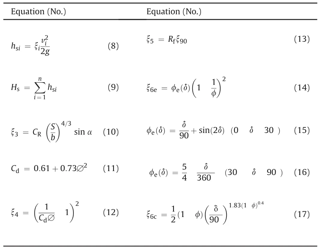
Table 2List of equations for singular losses calculation.
Also,bend loss is one of the significant parts of singular losses along the waterway system and it is even more pronounced in sharp bends with small radius.Fig.5 shows the bend loss coefficient(ξ90)as the function of ratio between bend radius(Rb)and width of the tunnel at bend(D)for 90?bend(Lysne et al.,2003).For bends with other angles,a reduction factor has also been proposed(Fig.5,right).The bend loss coefficient for different bend angles can be calculated by multiplying bend loss coefficient of 90?bend with a reduction factor described by Eq.(13).
The waterway systems have changes in cross-sectional area due to different shapes and tunnel linings.These changes result in transitions between two different sections and both expansion and contraction transitions are present as typically indicated in Fig.6a and b,respectively.In Fig.6,HL is the head loss from section 1 to section 2 and the velocity in smaller sections is considered to calculate head loss due to both expansion and contraction.According to Hager(2010),the loss coefficient in expansion can be expressed by Eq.(14),where experimentally measured values of φe(δ)are represented as a function of angle δ(Eqs.(15)and(16)).Similarly,Hager(2010)proposed a relationship for loss coefficient in contraction(Eq.(17)).
Additional niches are excavated in certain intervals along the headrace tunnel length in order to provide an extra space for laybys,vehicle parking,turning,storage of immediate construction materials and equipment.Lysne et al.(2003)studied the head loss due to niches and proposed a chart for head loss coefficient of niches,which is termed as loss coefficient due to the expansion of tunnel,ξ7(Fig.7).
In general,there is a rock trap at the end of unlined or shotcretelined tunnels in order to trap fallen rock blocks and coarse sand particles produced along the tunnel length and transported by the flow.The rock trap is constructed with the expansion of tunnel area at the invert.Therefore,it is considered similar to the niche in terms of head loss coefficient and the same chart(Fig.7)is used in the analysis.
3.Methodology for roughness evaluation
Initially,data and information from two hydropower projects(MKHP and CHP)were collected.Both projects have low-pressure headrace tunnels up to SSs.The remaining waterway segments from the SSs to the powerhouses are high-pressure shafts and tunnels.The CHP has a steel-lined penstock shaft and the MKHP has a combination of a concrete-lined horizontal pressure tunnel,a concrete-lined vertical shaft and a steel-lined horizontal penstock tunnel.The authors carried out head loss measurement in December 2015 at both low-pressure headrace tunnels and highpressure shafts and tunnels in both projects.
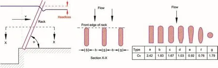
Fig.3.Head loss coefficient in trash rack(drawn based on Penche,2004).
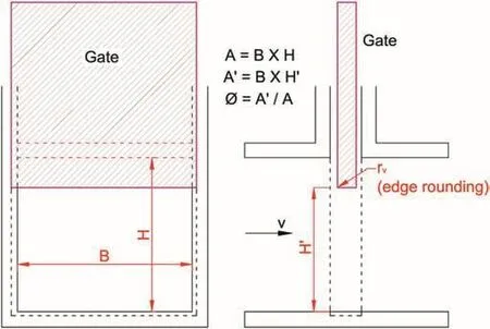
Fig.4.Slide type gate arrangement in the conduit.
Fig.8 shows the methodology used in predicting the roughness of tunnels at these two hydropower projects.As a first step of analysis(inside the black dotted rectangle in Fig.8),the roughnesses of the steel,concrete and shotcrete-lined sections of the tunnel and shaft(including invert concrete lining)have been backcalculated using the equations presented in Tables 1 and 2.In the back calculation,the measured head loss,discharge and geometry are known parameters and roughness is an unknown parameter.The calculated roughnesses of steel-and concrete-lined tunnels are considered as fixed entities for calculating the roughness of shotcrete-lined headrace tunnels with invert concrete as and when necessary.From the results of this back calculation,a new relationship between the Manning coefficient and physical roughness of a shotcrete-lined tunnel with invert concrete is proposed.
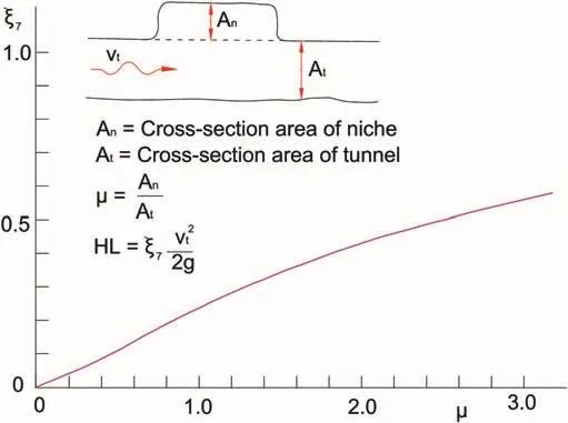
Fig.7.Head loss coefficient in tunnel expansion(drawn based on Lysne et al.,2003).
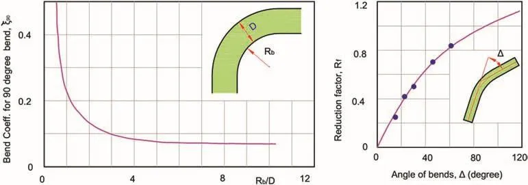
Fig.5.Bend loss coefficient chart(drawn based on Lysne et al.,2003).
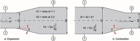
Fig.6.Transition between different sections(expansion and contraction).v1and v2represent the flow velocities at sections 1 and 2,respectively;and D1and D2represent the diameters at sections 1 and 2,respectively.
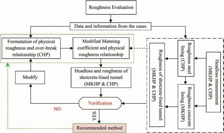
Fig.8.Methodology for roughness prediction in shotcrete-lined tunnels with invert concrete lining.
In the second step,statistical analysis is carried out to determine the extent of undulations in the surface of shotcrete-lined tunnel by using geometrical information of the selected cross-sections of the CHP.As a result of the analysis,a relationship has been developed between the physical roughness and over-break in the walls and the crown of the shotcrete-lined tunnel.By using this relationship,the physical roughness has been calculated from the data of actually measured over-break of all shotcrete-lined sections of the headrace tunnel documented in the as-built drawing of both projects.Since both headrace tunnels have shotcrete sections with invert concrete,the composite physical roughness of the whole cross-section is calculated as the weighted average of the shotcrete and concrete-lined sections.Further,the Manning coefficient(hydraulic roughness)is calculated from the physical roughness for each section using the proposed equation.Finally,frictional head loss in shotcrete-lined tunnels with invert concrete for both projects is calculated by using Eq.(5)and the established Manning coefficient.A new roughness prediction method is then proposed after verification of this calculated head loss with the one measured in the field.
4.Case studies
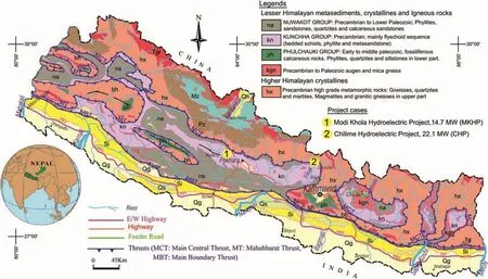
Fig.9.Project locations in geological map of the Nepal Himalaya.
The locations of two hydropower projects are shown in the geological map of Nepal(Fig.9).As seen in the figure,both the CHP and MKHP are located in the Lesser Himalaya meta-sedimentary rock formations.The drill-and-blast method of excavation was used for the construction of all underground works of both projects.
4.1.Modi Khola hydroelectric project
The MKHP is located in central-west part of Nepal at Nayapul,Parbat district,which is about 45 km to the northwest of Pokhara(Fig.9).Water from Modi Khola at Nayapul is diverted to the right bank and all project components are built on the same bank.The headworks components of this project consist of a diversion weir,an open concrete canal,desanding basins and a regulating poundage.The regulating poundage is used for head and discharge regulation.From the poundage to the powerhouse,water is transferred through a headrace tunnel,a vertical pressure shaft and a horizontal pressure tunnel and to the semi-underground powerhouse located at Patichaur.The project has a surface powerhouse with an installed capacity of 14.7 MW generated by utilizing 27.5 m3/s design discharge and a gross head of 71 m.The main rock types in the project area are quartzite and phyllitic schist(Shrestha and Panthi,2014).The headrace tunnel mainly passes through quartzite.
The total length of the headrace tunnel is 1507m,which extends from the regulating pond(RP)to the surge shaft(SS)of the project.The headrace tunnel is composed of different sections of concrete linings and shotcrete linings(Fig.10).The designed shape of the headrace tunnel is an inverted D.The cross-sectional area of concrete-lined section is very close to constant.On the other hand,the cross-sectional area of shotcrete-lined section varies due to blasting effect.However,the invert of the whole headrace tunnel is lined with concrete.
As shown in Fig.10,there are three stretches of tunnel downstream of the SS,i.e.a 42 m long horizontal inverted D shaped headrace tunnel,connecting the SS with the top of the vertical shaft,a vertical shaft of circular shape with a transition between horizontal tunnel,a circular tunnel before the start of the curve at the top,and a pressure tunnel from the bottom of vertical shaft to the powerhouse.The pressure tunnel consists of a circular concrete-lined tunnel and a circular steel-lined tunnel.Typical cross-sections of the tunnel with different lining conditions are shown in Fig.11.
Each of three different linings indicated in Fig.11 has different roughnesses against water flow.Even though this article mainly focuses on the roughness of shotcrete-lined tunnel with invert concrete,it is necessary to find out the roughness of both concrete and steel linings for calculation of the roughness from measured head loss.
4.2.Chilime hydroelectric project
The CHP is located in Chilime and Syabrubesi Village Development Committees in Rasuwa District in Central Nepal(Fig.9).The project has an installed capacity of 22.1 MW with the design discharge of 7.5 m3/s and gross head of 345 m.Water from Chilime River is diverted to the right bank of the river and reaches the regulating pound followed bydesanding basin,conduits and canals.The main purpose of the poundage is to regulate water level and to function as peaking reservoir.Water from the poundage to underground powerhouse is transported through the underground headrace system consisting of a pressure conduit,headrace tunnel and inclined penstock shaft.The water is then discharged back to the Bhotekoshi River through a tailrace tunnel(Fig.12).Geologically,the project area lies in the Lesser Himalaya meta-sediments and the main rock types in the project area are quartzite and mica schist(CHC,2005).
There exists a 425 m long pressure conduit with a syphon from the inlet gate downstream of the RP to the headrace tunnel inlet portal,of which 395 m is concrete box and the rest is circular steel pipe.The total length of headrace tunnel(HRT)from inlet portal to SS is 2827 m.The headrace tunnel consists of tunnel segments with concrete lining and shotcrete lining with invert concrete,and steel lining.Concrete lining segments of the headrace tunnel have two different shapes,i.e.horse-shoe and inverted D shapes.The inclined shaft and pressure tunnel from SS to powerhouse are embedded with steel penstock pipe,which has a total length of 650 m.
Fig.13 shows typical sections of the headrace system representing each lining system.These sections are the basis for the calculation of flow velocity and hydraulic radius of each headrace system,which are used chainage-wise as lining types for head loss calculation.
5.Analysis of roughness
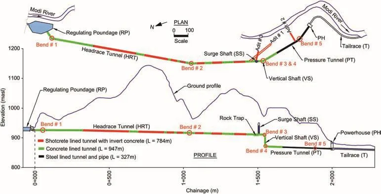
Fig.10.Plan and profile along the MKHP,Nepal(drawn based on Shrestha and Panthi,2014).masl represents meter above sea level.
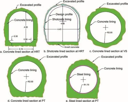
Fig.11.Typical sections at different stretches of tunnel in the MKHP(unit in meter)(drawn based on Sharma,2001).
Shotcrete-lined pressure tunnels are feasible only if the economic loss caused by the friction head loss is much less than the cost needed for full concrete or steellining.The head loss and hence the friction loss have to be measured once the hydropower project enters to the operation phase and the loss has to be verified whether it is within the design limit.The roughness of different linings in tunnels can be back-calculated from measured head loss.However,roughness needs to be predicted before and during the excavation of the tunnel in order to cope with design and contractual issues.
5.1.Head loss measurement
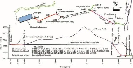
Fig.12.Plan and profile along waterway alignment of the CHP(Source:Chilime Hydropower Company Ltd.).
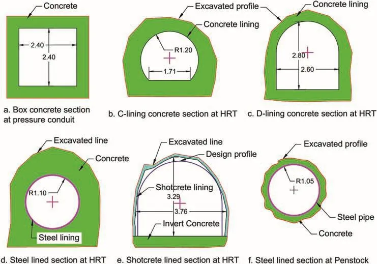
Fig.13.Typical sections at different stretches of waterway systems of the CHP(unit in meter).
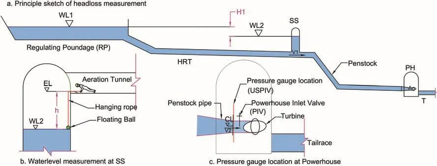
Fig.14.Typical sketch of head loss measurement locations and details.
Head loss measurement was carried out in both the MKHP and CHP.In each project,the head loss has been measured in two stretches:one is from the RP to the SS and another is from the SS to the upstream of powerhouse inlet valve(USPIV).The schematic diagram of measurement locations including project components is shown in Fig.14.The water level at the SS was measured multiple times using a floating ball hanging from the invert of the aeration tunnel at the SS.At the time of measurement,the water level at the RP and pressure at the USPIV were recorded from the data monitoring system of the projects and maintained constant throughout the measurement.The constant values were achieved by maintaining constant discharge and constant power production.
Head loss in different stretches has been calculated using the equations listed in Table 3.Head loss from the RP to the SS is calculated using Eq.(18),whereH1is the water level difference between the RP and the SS(Eq.(19))andV1is the velocity of water in the tunnel at the location of the SS(Eq.(20)),Qis the water discharge in m3/s andA1is the cross-sectional area of the tunnel at the SS location in m2.
Water level at the SS is calculated using Eq.(21),whereELis the elevation at the invert of aeration tunnel andhis the vertical heightbetweenWL2andEL,which is measured with the help of a floating ball hanging as shown in Fig.14b.ELis taken from as-built drawing of the SS provided from the respective projects.Furthermore,the head loss from the SS to USPIV is calculated by using Eq.(22),whereCLis the center elevation level at the USPIV(Fig.14c),Pris the pressure in bar at the USPIV,V2is the flow velocity at the USPIV and γwis the unit weight of water(9.81 kN/m3).Finally,Eq.(23)is used to calculateV2from the discharge at the USPIV(Q1)and pipe diameter(d).Even though both projects have two turbine units,only one unit was in operation in the MKHP at the time of measurement.This givesQ1in the MKHP as the total discharge of the plant.
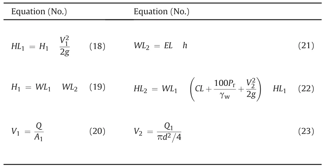
Table 3List of equations used to calculate head loss at different stretches.
During the measurement,total power production(Pw)was also recorded from the control panel at the powerhouse.Using Eqs.(18)-(23)and input data in Table 4,bothHL1andHL2are calculated for each measurement for both projects(Table 5).As one can see in Table 5,there were 8 measurements at the MKHP and 12 measurements at the CHP.
5.2.Roughness from measured head loss
One of the major parameters to calculate the roughness from measured head loss is frictional head loss.The frictional head loss in the considered tunnel stretch has been calculated after subtracting all other losses from total measured head loss.Once the frictional head loss,water discharge and tunnel geometry are known,roughness is the only parameter to be calculated which is unknown in the head loss equations(Eqs.(2)and(5)).As shown in Fig.12,at the CHP,there is a steel penstock lining from the SS to the USPIV.The roughness of the steel penstock lining is back-calculated from this section.At the MKHP,both steel and concrete linings are used in part of pressure tunnel and vertical shaft(Fig.10).In this stretch,the roughness of the concrete-lined tunnel is back-calculated with the help of the established roughness of the steel lining.By fixing the roughness of the concrete and steel linings,the roughness of shotcrete-lined tunnel with invert concrete sections is calculated along the headrace tunnels of both the CHP and MKHP.
5.2.1.Roughness for steel lining
There are altogether three bends in the penstock,but along unit#1 in the powerhouse,there is no bend from Y-furcation.As shown in Fig.12,the SS itself is along the bend and loss due to this bend is considered in penstock part.Unit#1 is taken into account in the calculation and hence effective bends in the penstock are bends#6,#7 and#8(Table 7).
Based on Tables 6 and 7,the total singular loss(Hsin Eq.(9))in this particular case will be 0.197 m(=0.161 m+0.036 m).Furthermore,friction loss in steel-lined part(Hfs)is calculated by subtractingHsfrom each value ofHL2in Table 5.Eqs.(2)and(3)are merged and the roughness for steel lining(εs)is established for the first friction loss for the given length of tunnel,geometry of tunnel and discharge(ε in Eq.(3)is εs).Here,εsis considered as a constant parameter irrespective of the size of tunnel,but the friction factor ofsteel pipefsslightly changes with the size and again Eq.(3)is used to calculatefsfor different sizes.Similarly,Manning coefficient of steel pipeMsis calculated by using Eq.(6)for eachfsand the result is shown in Table 8.
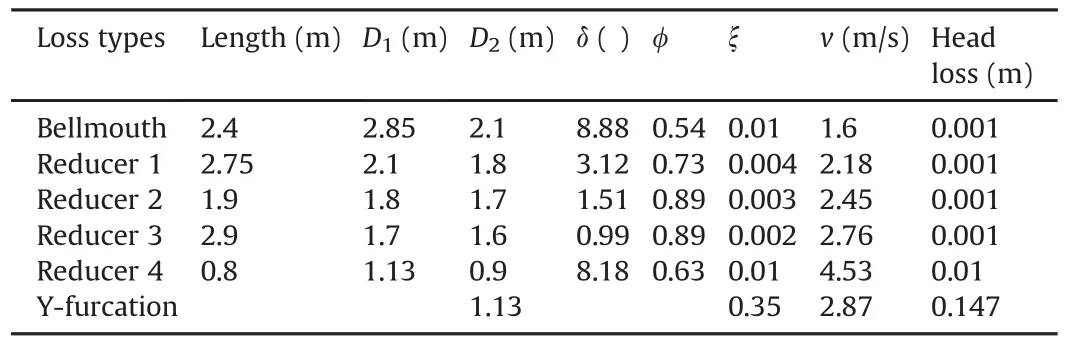
Table 6Bellmouth,reducers and Y-furcation losses from the SS to the USPIV of CHP.Total head loss=0.161 m.

Table 4Input data for the head loss measurement of both MKHP and CHP.
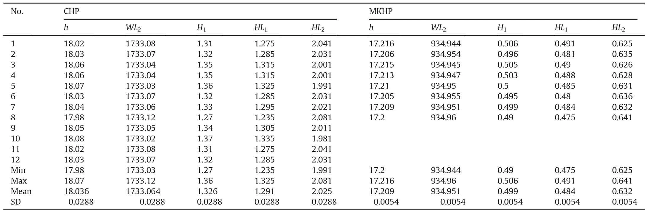
Table 5Head loss(in meter)at the waterway systems of both MKHP and CHP.
Following the same calculation steps as in Table 8,εsfor all head loss measurements(Hfs)is calculated and presented in Table 9.The table also shows average values offsandMsfor each length and size of the penstock pipe for all measurements.Further,the mean value of εsshown in Table 9 will be used as the fixed roughness for steel lining.
5.2.2.Roughness for concrete lining
As shown in Fig.10,the MKHP has both concrete lining and steel lining from the SS to the USPIV.In this stretch,friction loss inconcrete-lined tunnel(Hfc)is calculated by subtracting singular losses and friction loss in steel-lined tunnel fromHL2.For singular losses,the calculation process is the same as that for the previous case.Calculated values of reducer loss,bend loss and Y-furcation loss are presented in Table 10.
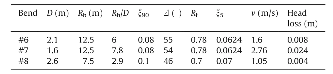
Table 7Bend loss calculation in the stretch from the SS to the USPIV of CHP.Total head loss=0.036 m.
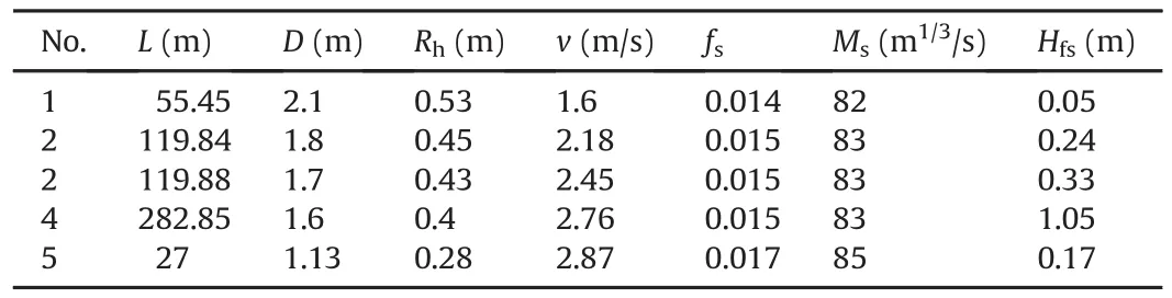
Table 8Roughness of steel lining(εs=0.551 mm)between the SS and the USPIV of CHP for the first measurement.Total Hfs=1.84 m.
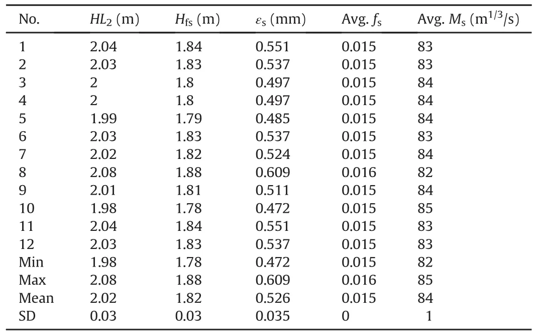
Table 9Roughness of steel lining(εs)between the SS and the USPIV of CHP.
Friction loss in the steel-lined pressure tunnel of the MKHP is calculated for the given length,size and established roughness of steel lining.The roughness of steel-lined pressure tunnel is equal to 0.526 mm(mean value of εsin Table 9)and friction loss is equal to 0.2 m.Total fixed loss is then 0.605 m,which is the sum of total singular loss and friction loss in steel-lined tunnel.Furthermore,friction loss in the concrete lining(Hfc)section is calculated by subtracting the total fixed loss frommeasured head loss(HL2)of the MKHP.For given geometry and length of concrete-lined tunnel,the roughness of the concrete lining(εc)is back-calculated fromHfcby using Eqs.(2)and(3),following the same calculation steps as in Table 8 for each measurement ofHfc.In addition to this,average values offcandMcare also calculated as that in Table 8 and shown in Table 11.
Table 11 shows the final result of the roughness of the concretelined tunnel of the MKHP for all eight measurements.The final value of εcis the average of all eight measurements and is used as afixed value for further calculations.
5.2.3.Roughness for shotcrete-lined tunnel
与此同时,要创新活动形式。课堂上思政内容的学习是一方面,另一方面,可以配合课堂内容开展如政策专题讨论、党史知识竞赛、演讲比赛、诗歌朗诵等活动。在一些重要纪念日可以带领学生走出校园,参观纪念馆、烈士陵园等,缅怀革命先烈,对学生进行“情境教育”,引导学生牢记历史。
Both the CHP and MKHP have shotcrete-lined headrace tunnels with invert concrete(Figs.11b and 13e).Roughness of shotcretelined tunnel is back-calculated from frictional head loss for stretches with shotcrete lining.The back-calculated roughness is the equivalent roughness of shotcrete linings in the walls and crown and concrete lining in the invert.
Since the headrace tunnel of the MKHP has both concrete lining and shotcrete lining,the total head lossHL1is the sum of friction losses in shotcrete and concrete-lined tunnels and singularlosses in the system.The total singular losses and friction loss in concretelined segment are considered as fixed losses for the given discharge.Table 12 shows input data required to calculate head loss in trash rack,gate,niches,rock trap and bends.
In addition,there are a total of 18 transitions between concrete to shotcrete and shotcrete to concrete linings.The loss coefficients of these transitions are estimated by using Eqs.(14)and(17).The detailed calculations of head loss due to transitions are made and the final results with all other singular losses are presented in Table 13.
Another fixed loss in the system,the frictional loss in the concrete-lined tunnel(Hfc),is calculated using Eqs.(2)and(3)with the established value of εcand given geometry and length of concretelinings.The totalHfcis equal to0.197 m and the total fixed loss,including singular losses,becomes 0.275 m.Finally,friction loss in shotcrete-lined tunnel(HR)is calculated by subtracting the total fixed loss from measured head loss(HL1)of the MKHP.A chainagewise calculation spreadsheet for 18 shotcrete-lined tunnel sections is prepared with input parameters to calculate εR,fRandMRfor eachHRfollowing exactly the same calculation process as given earlier inconcrete and steel linings,which are calculated as 0.18 m,0.13 m and 0.64 m,respectively.These losses are calculated in detail by using project data and information and previous calculation procedures.By subtracting the fixed losses fromHL1,the friction loss in the shotcrete-lined tunnel(HR)is calculated,which is shown in Table 14.In order to calculate the roughness of shotcrete-lined tunnel,a chainage-wise calculation spreadsheet is prepared for 299 tunnel cross-sections and the same calculation process is also employed as that for the MKHP.
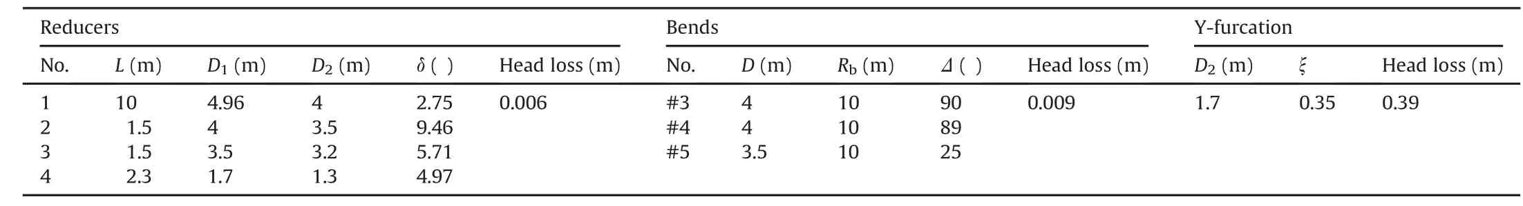
Table 10The singular losses in the SS to the USPIV of MKHP.Total singular losses=0.405 m.
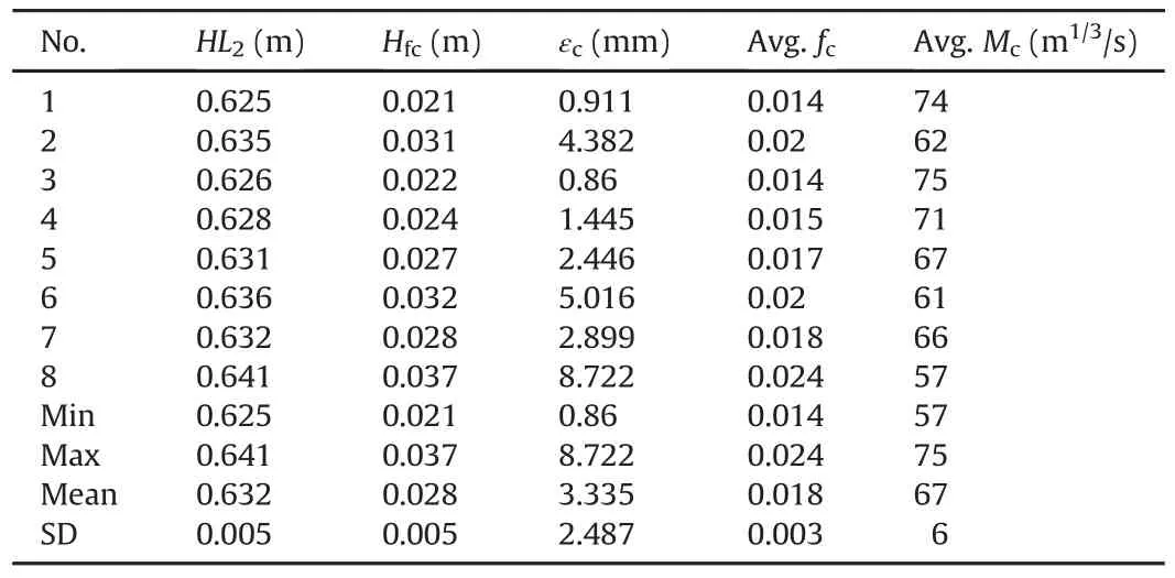
Table 11Roughness of concrete-lined tunnel of MKHP.
As shown in Table 14,the hydraulic roughness fromboth Darcy-Weisbach(Eqs.(2),(4)and(6))and Manning for mulae(Eqs.(5)and(7)) corresponds very well in both projects.Table 14 also shows the minimum,maximum and mean values of different roughnesses.Table 8,where Eq.(3)is replaced by Eq.(4).The outcome of these calculations is presented in Table 14.Additionally,MRand εRare also calculated by using Eqs.(5)and(7),respectively,and the results from the two different approaches are compared.
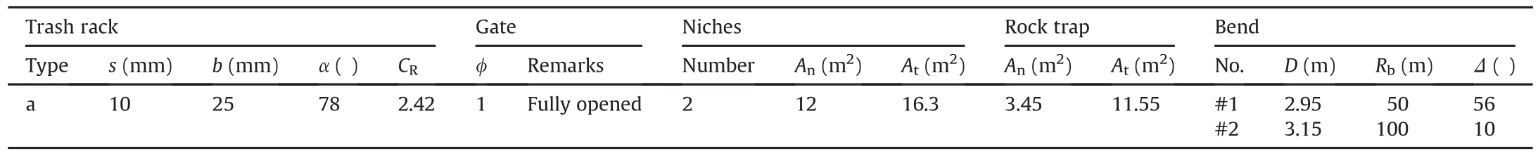
Table 12Geometrical and technical data for singular losses in the HRT of MKHP.
In the case of the CHP,the total head loss(HL1)is the sum of singular losses and friction losses in concrete box culvert,steel pipe,steel-lined tunnel,concrete-lined tunnel and shotcrete-lined tunnel.Fixed losses in this case are singular losses and friction losses in
5.2.4.Manning coefficient and physical roughness
The physical roughness,εR,from both the Darcy-Weisbach and Manning approaches in Table 14,has some deviation in the results for both projects,which indicates that modification in Eq.(7)is needed in order to define εRas a physical roughness equivalent to sand roughness given by Eq.(4).In this endeavor,an attempt is made to establish a modified relationship between Manning coefficient(MR)from Eq.(5)and equivalent sand roughness(εR)derived from the Darcy-Weisbach and Colebrook relationships(Eqs.(2)and(4))using 20 results presented in Table 14(Fig.15).
As Fig.15 indicates,in comparison to theMRvalues for shotcrete-lined tunnel with invert concrete lining back-calculated in Table 14,Eq.(7)gives lowerMRvalues for the same values of εR.Therefore,the authors suggest that the relationship betweenMRand εRfor shotcrete-lined tunnels with invert concreteis defined by Eq.(24),which shows a good fit in Fig.15:
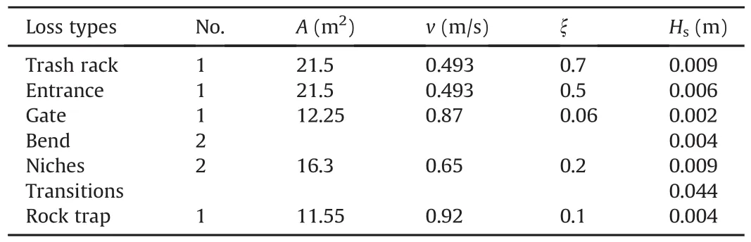
Table 13Singular losses in the HRT of MKHP.Total singular loss=0.078 m.
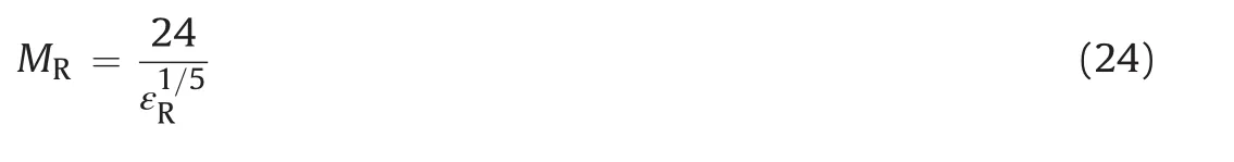
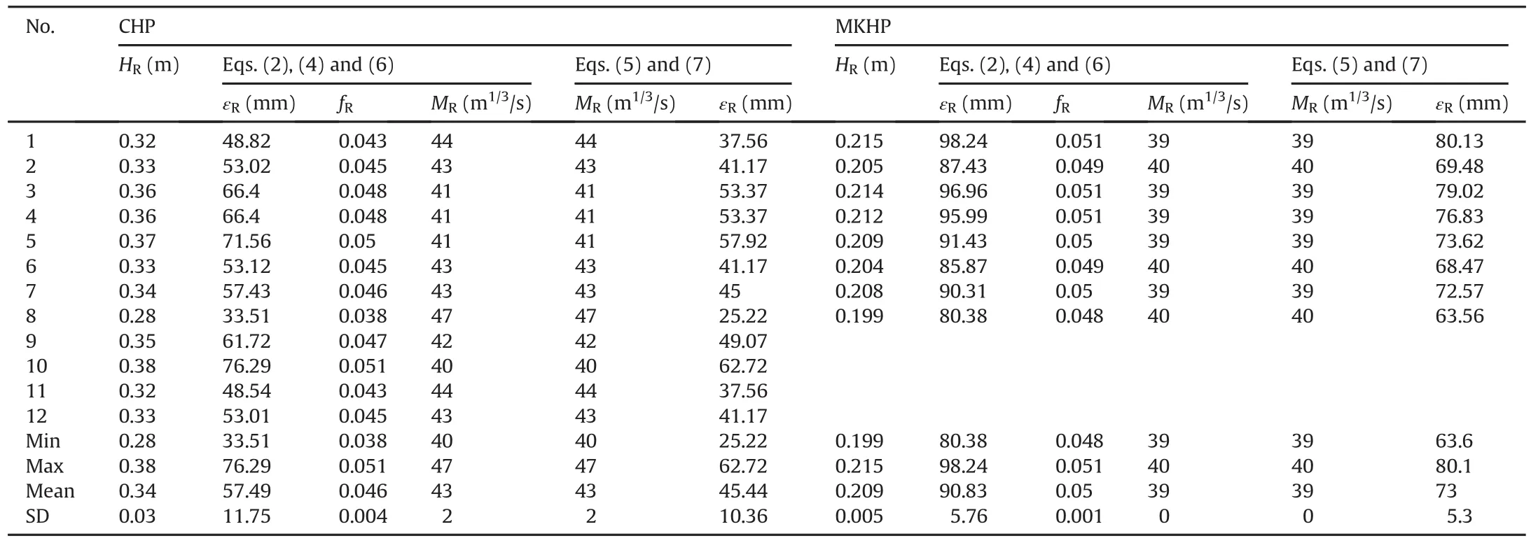
Table 14Roughness of shotcrete-lined tunnel with invert concrete in the HRT of CHP and MKHP.
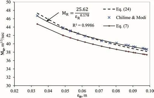
Fig.15.Relationships between MRand εRbased on different approaches.
The benefit of this equation is its simplicity in comparison to the one with Darcy-Weisbach and Colebrook equations.Moreover,Darcy-Weisbach and Colebrook equations do not consider different lining scenarios in the same cross-section of the tunnel.However,the authors emphasize that Eq.(24)is derived based on 20 datasets from two shotcrete-lined tunnels with invert concrete and it should be tested with many other tunnels with similar lining conditions,which are becoming more common in the Himalayan region and other part of the world such as the Andes.
5.3.Physical roughness in relation to over-break
If a correlation between the average over-break thickness and the undulations in actual tunnel profile is established,it may be possible to predict roughness.With this concept in mind,an attempt has been made to find a correlation between roughness and mean over-break thickness using actual cross-section data of the headrace tunnel of the CHP where the tunnel cross-sections are mapped at either every 5 m or 10 m.These records of tunnel crosssections are used to establish a correlation between over-break and physical roughness of the tunnel surface.The achieved correlation is further tested with the over-break and roughness properties of the MKHP headrace tunnel.
The cross-section profile of a blasted tunnel seldom meets the profile assumed in a design profile and differs from it with an undulating wall surface as shown in Fig.16.A shotcrete-lined tunnel follows almost similar surface conditions as in an unlined tunnel and hence has similar undulation along the tunnel periphery excluding the invert,which is mostly concrete-lined in the Himalayan water tunnels.
Hence,the roughness of a shotcrete lining(walls and crown in Fig.16)can be calculated using undulation depth measured from the minimum area profile as shown in Fig.16.In case of excavated tunnel sections,the minimum area profile may or may not coincide with the designed area profile depending on the quality of the contour blast.However,the shape of the minimum area profile is the same as that of designed profile(i.e.inverted D in this article).Since the minimum area profile follows innermost projections of the excavated profile or the shotcrete-lined profile,the undulation depth(Xi),which is measured perpendicular to the minimum area profile,is always equal to or greater than zero.There is statistical variation of undulation depth around the tunnel profile which demands that a single representative value of undulation depth is needed to estimate the equivalent sand roughness.According to Adams et al.(2012),depending on the type of undulating surface,different statistical parameters(calculated from the undulation depth)can be used to convert the undulation depth to the equivalent sand roughness.One of such parameters is the square root of variance of the undulation depth(Pegram and Pennington,1998;Adams et al.,2012).In this article,the square root of the variance ofXiis assumed to be equal to the physical roughness(equivalent sand roughness)of the unlined or shotcrete-lined profile of the tunnel in question and is expressed by
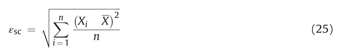
wherenis the number of undulation depths,andXis the average of undulation depths.
The mean area(Am)shown in Fig.16 is equal to the actually excavated area or area after shotcrete lining(Ae)of the tunnel in question.The mean area profile of the tunnel can be drawn to match the profile of the minimum area(Amin)maintaining uniform thickness(tm)around walls and crown.The thickness(tm)is therefore the mean over-break thickness for the cross-sectional profile in question and is calculated by
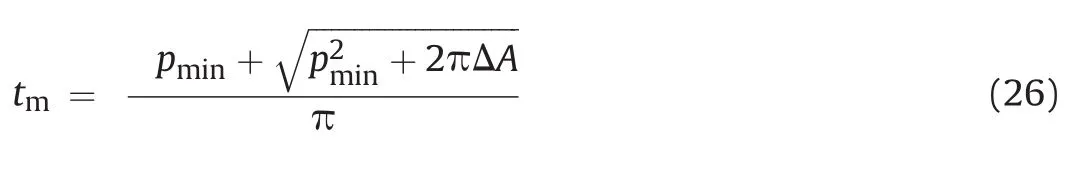
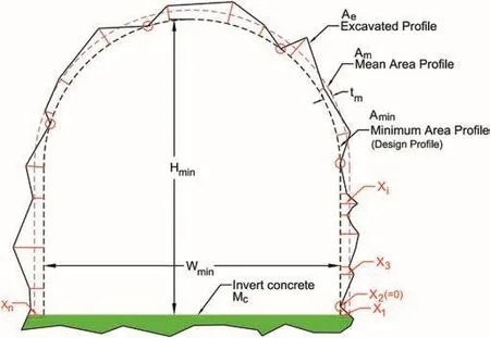
Fig.16.Roughness of unlined or shotcrete-lined tunnel with invert concrete.
wherepminis the perimeter of walls and crown of the minimum area profile andΔAis the over-break area(=Ae?Amin).
At the CHP,299 tunnel cross-section profiles were surveyed at either every 5 m or every 10 m of shotcrete-lined headrace tunnel with invert concrete lining.Out of these cross-sectional profiles,68 sections from chainage 0+105 m to 0+490 m are taken as representative cases for the measurement of roughness in walls and crown.The tunnel stretch is selected as representative considering the fact that it is the longest tunnel stretch where shotcrete lining is continuous.In this stretch,Xiis measured in each cross-section and the number of measurements is governed by the extent of undulations presented in the profile in question and varied from 11 to 16 measurements for each section.εscandtmare calculated for each section by using Eqs.(25)and(26),respectively,and the values are used to find out whether there exists any correlation between these two properties(Fig.17).
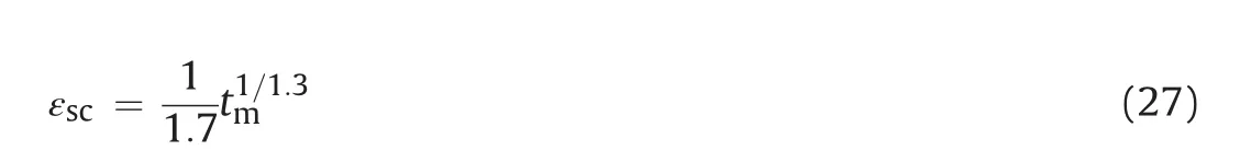
As Fig.17 indicates,the correlation between εscandtmis found satisfactory with a regression coefficient(R2)exceeding 80%.More importantly,Eq.(27)is proposed based on the result achieved,
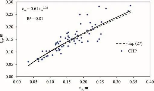
Fig.17.Correlation between roughness and mean over-break thickness.
which is slightly modified with the one shown in Fig.17,to improve the readability of the equation without any impact on the calculation results:
It is important to note that Eq.(27)represents only the walls and crown of a shotcrete-lined tunnel.Since there is concrete lining in the invert,the whole cross-section becomes composite lining,which should be analyzed accordingly.In this respect,the roughness of the composite lining is considered as the weighted average with respect to perimeter and can be defined by where the roughness of invert concrete lining εcis equal to 3.34 mm,i.e.the same as that of a concrete-lined tunnel(mean value in Table 11).It is considered as a fixed parameter over the entire length of the shotcrete-lined tunnel.
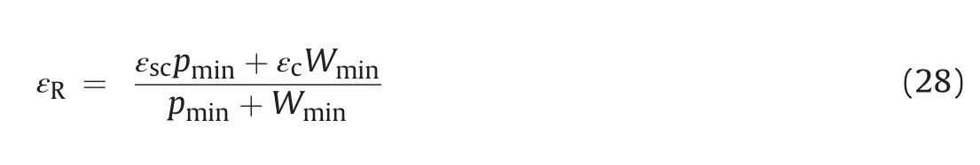
The proposed Eqs.(24)and(27)are further used in all shotcretelined sections of headrace tunnels of both the MKHP and CHP to calculate both physical and hydraulic roughnesses.In this regard,all 299 measured cross-sectional profiles from the CHP and 18 cross-section profiles from the MKHP are exploited.For each section,εscis first calculated by using Eq.(27)for respective measuredtm.Furthermore,Eq.(28)is used to calculate εRand finallyMRis calculated using Eq.(24)suggested by the authors.Furthermore,frictional head loss is calculated by using Eq.(5)and exploiting respectiveMRvalues,cross-sections and length of tunnel(Table 15).
As Table 15 indicates,there is fairly good match between measured and calculated head losses with approximately 15%deviation at the CHP.However,the results obtained for the MKHP are extremely good with a deviation of only 3%.
Furthermore,Eq.(24)is inserted in the chart drawn by Solvik(1984),for both the Manning and Darcy-Weisbach formulae as shown in Fig.18.As Fig.18 indicates,the proposed Manning formula for shotcrete-lined tunnel with invert concrete fits very well with the Darcy-Weisbach equations for the inverse of relative physical roughness range between 20 and 100,which is verylogical since the Manning coefficient for shotcrete-lined tunnels with invert concrete in general should vary between 35 and 50 depending on the quality of tunnel contour excavation.
Hence,it is concluded that the proposed equations,such as Eq.(24),can be used in shotcrete-lined tunnels with invert concrete to estimate the Manning coefficient and Eq.(27)can be used to predict physical roughness of shotcrete-lined surface.However,the authors highlight that the suggested equations are based on only two waterway systems and recommend that these equations are further verified using data from other projects.
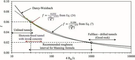
Fig.18.Comparison of Darcy-Weisbach and Manning formulae(updated in Solvik,1984).
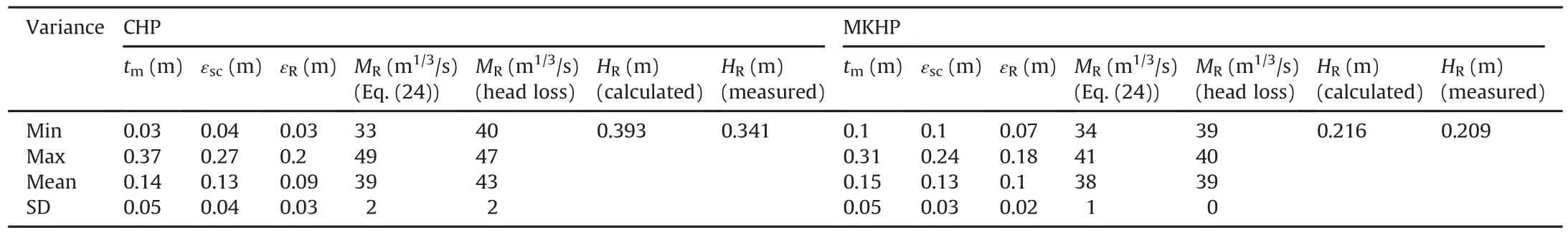
Table 15Head loss and roughness of shotcrete-lined tunnel with invert concrete of both CHP and MKHP,calculated using proposed equations.
5.4.Roughness from existing methods
The existing methods,such as those proposed by Rahm(1958),Priha(1969)and Reinius(1970),for calculating tunnel roughness were also tested to calculate the roughness of shotcrete-lined tunnel of the CHP.Altogether,299 cross-sections of shotcretelined tunnel are used for the calculation.Regarding the MKHP,available cross-sections are not enough to apply these existing methods.Hence,Table 16 shows only the result for the CHP.
The roughness obtained from the existing methods is higher than that from the actual head loss measurement at the CHP.It is important to highlight that the existing methods(Rahm,1958;Priha,1969;Reinius,1970)of roughness calculation were mainly established using data sources from unlined tunnels,and hence result in higher roughness predictions than appropriate for the tunnels with shotcrete and invert concrete lining.On the other hand,roughness obtained by using the equations proposed by the authors is closer to the back-calculated value based on the measured head loss of the CHP.Therefore,we claim that,for the composite lining consisting shotcrete and invert concrete,the proposed equations(Eqs.(24)and(27))have better reliability.
6.Over-break(excavation)vs.rock mass quality
The extent of over excavation on the tunnel excavated using the drill-and-blast method depends upon the quality of rock mass along the tunnel in question,type of blast methods(wedge cut/burn cut),length of drill holes,type and amount of explosive used and professional quality and awareness of the tunneling team involved in tunnel excavation work.As discussed above,the tunnel roughness is greatly influenced by the quality of excavation.In the following,the authors try to assess to what extent the rock mass quality influences the over-break thickness expressed bytm.The average or smoothened over-break thickness(tm)of 299 and 77 excavated tunnel cross-sections for the CHP and MKHP,respectively,has been calculated.The calculated over-break thickness(tm)is then plotted against mapped values of rock mass class defined by Q-system of rock mass classification(Fig.19).
As Fig.19 indicates,there is no clear correlation between over break thickness(tm)and rock mass quality class.Even though the rock types along these two headrace tunnels are similar and represented by jointed quartzite,the variation intmvalues at the CHP is found to be more pronounced in all rock mass classes than that at the MKHP.This is most likely related to professional quality and awareness of the tunneling team involved during the excavation.However,Fig.19 depicts one very important piece of information,which explains that the variation in over-break thickness in poor rock mass(Class IV)is higher than that of other rock mass quality classes.The authors believe that this is quite logical since the rock mass with Class IV according to Q-system typically has more than three joint sets and is blocky in nature.On the other hand,Class V represents very poor quality rock mass,where blasting length in each round is reduced(in general less than 1.5 m)to make sure that there is no tunnel collapse immediately after blasting.Lowerblasting round length reduces protrusion depth and therefore a reducedtmvalue.Another finding of this analysis is that the average over-break thickness seems to be between 0.1 m and 0.2 m in the blasted tunnels excavated using the drill-and-blast tunneling technique.
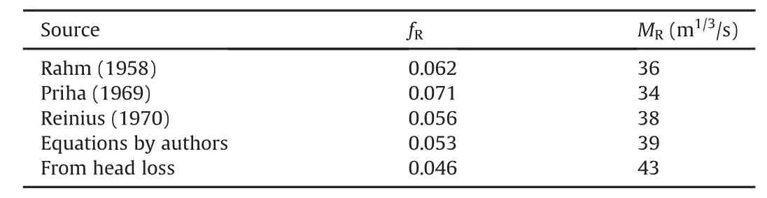
Table 16Roughness of shotcrete-lined tunnel with invert concrete using existing methods in CHP.
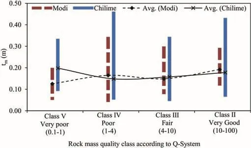
Fig.19.Smoothened over-break thickness(tm)against rock quality class according to Q-system of rock mass classification at CHP and MKHP.
7.Cost optimization
Traditionally,using a fully concrete-lined waterway system has been proven to be a costly solution due to extra need for construction resources and time.Therefore,innovative solutions are needed to reduce the fully concrete-lined length of the pressure tunnel system(in particular,low-to medium-pressure headrace and tailrace tunnels).On the other hand,innovative applied solutions must guarantee long-term stability and sustainability,cost effectiveness and construction time savings.Tunnel rock support,consisting of sprayed concrete and systematic bolting,is applied to almost all waterway tunnels constructed today in the Himalayan region.This is mainly to secure tunnel stability and also to guarantee the safety of working crew at the tunnel face.Hence,applied support should be capable of withstanding any type of tunnel collapses including block fall(Panthi,2015).
The basis of cost optimization is hence the use of shotcrete-lined headrace and tailrace tunnels with invert concrete instead of traditional concrete-lined tunnels.However,the construction cost of such tunnels should guarantee reduced construction cost and time.In addition,the waterway system should also be able to generate similar or higher financial revenue than that of concretelined tunnels.Regarding the waterway system,the main long-term revenue loss can be related to the frictional head loss.To evaluate this economic impact,in the following,a range of hydraulic roughness values for shotcrete and concrete-lined tunnels have been chosen for each lining type.Hydraulic roughness in concrete lining(Mc)is considered to vary from 60 to 75 and in a shotcretelined tunnel with invert concrete(MR),it is considered to range from 35 to 50.The shape of the tunnel was chosen as inverted D with equal width and height for both concrete-lined and shotcretelined tunnels in order to ensure a hydraulically efficient shape of the tunnel(Lysne et al.,2003).The ratio between the area of a concrete-lined tunnel(Ac)and the area of a shotcrete-lined tunnel with invert concrete(Asc)for equal head loss can be expressed by
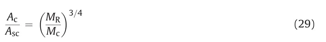
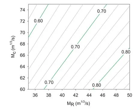
Fig.20.Area ratio(Ac/Asc)for different roughness values for the same hydraulic head loss.
The area ratio is calculated for all possible combinations within the given range of roughness,as presented in Fig.20.The contour lines in the figure are an area ratio that helps to find equivalent area of concrete-lined tunnel for a known area of shotcrete-lined tunnel and vice versa.
After having equivalent areas,the quantities of excavation and rock support have been calculated for each lining case.It is considered that there is a need for initial rock support consisting of sprayed concrete and systematic bolting to achieve construction safety in the tunnel.Even though the extent of this initial support is dependent on the quality of rock mass,it is considered that on average,10 cm fiber reinforced shotcrete and rock bolts(3 m long@1.5 m×1.5 m spacing)are required as initial tunnel support.The final lining required for shotcrete-lined tunnel is assumed as 40 cm thick reinforced concrete lining in the invert and 5 cm extra shotcrete lining and 20%extra rock bolts.The concrete-lined tunnel on the other hand is assumed to have 40 cm thick reinforced concrete along the tunnel periphery including tunnel invert.For cost calculation,the unit rate for each item has been fixed based on present market rates prevailing in Nepal(Himal Hydro,2016)and adjusted with global market rates based on international experience.Table 17 shows the adjusted unit rate for different main items.
All possible area and roughness ratios have been calculated within the given range of roughness.Construction cost per meter tunnel is calculated for both shotcrete-lined and concrete-lined tunnels with varying area ratio where the area of shotcrete-lined tunnel varies from 10 m2to 80 m2.Fig.21 shows the possible cost saving as a fraction of excavation cost per meter shotcretelined tunnel with invert concrete for different area ratios and roughness ratios.
As Fig.21a indicates,a cost saving is possible to achieve for all sized shotcrete-lined tunnels against concrete-lined tunnels as long as the area ratio is over 0.5.The figure also indicates that the cost savings are more pronounced in tunnels with smaller crosssectional area.Fig.21b indicates the cost savings for different tunnel cross-sectional areas in the form of ratio of roughness for shotcrete-lined and concrete-lined tunnels,which may also be used as a basis for cost optimization.
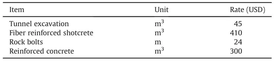
Table 17Unit rate of different support items.
8.Conclusions
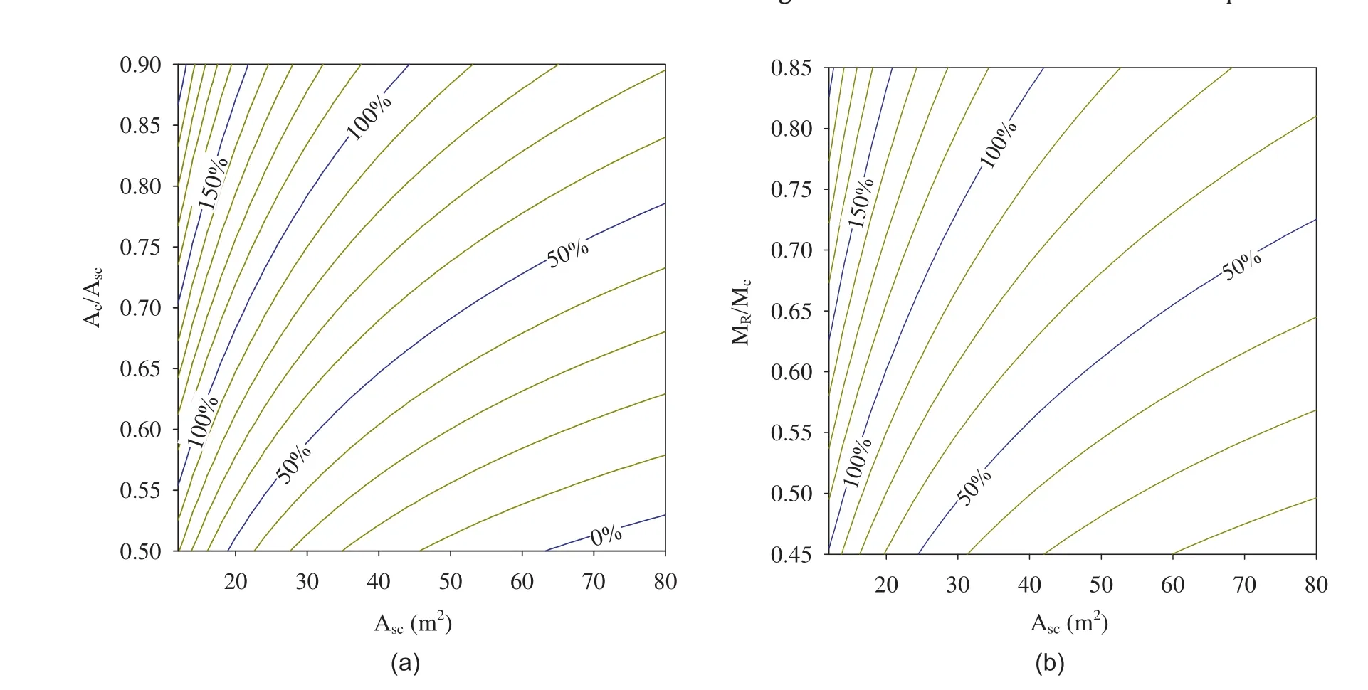
Fig.21.Contour lines showing possible cost saving as a fraction of excavation cost per meter of shotcrete-lined tunnel with invert concrete.(a)Area ratio,and(b)Roughness ratio.
As has been demonstrated in this article,shotcrete-lined waterway tunnels(both headrace and tailrace tunnels)with invert concrete will be innovative and optimal cost effective options for the future hydropower projects in the Himalayan region.However,one should make sure that the long-term stability and safety of the waterway system are achieved and tunnel segments crossing serious weakness/fault zones are fully concrete-lined.Suggested relationships between the Manning coefficient(hydraulic roughness)and the physical roughness(Eq.(24)),and between the physical roughness and the over-break thickness(Eq.(27))of tunnels excavated using drill-and-blast methods can be used to predict head loss along the shotcrete-lined tunnels with invert concrete. These relationships may be used for predicting tunnel roughness both before and after excavation of a waterway tunnel in question.The strength of the suggested relationships is their simplicity and the relationships are directly linked with the roughness of actual tunnel periphery.However,the authors note that the proposed equations are based on only two tunnel cases and hence assume that there may be some discrepancies in the outcome of the proposed method compared to the reality.Similarly,it is also concluded that there is no distinct correlation between over-break thickness(directly linked with the roughness of the tunnel periphery)and rock mass quality class defined by Q-system of rock mass classification.However,the study indicates that the rock mass quality under Class IV(poor rock mass)seems more vulnerable to the deviation on the over-break thickness.Finally, the study demonstrates the financial attractiveness of the use of shotcrete-lined waterway tunnels with invert concrete lining versus fully concrete-lined tunnels.
Conflicts of interest
The authors wish to confirm that there are no known conflicts of interest associated with this publication and there has been no significant financial support for this work that could have influenced its outcome.
Acknowledgements
The authors are grateful to the project operation team of the Modi Khola and Chilime hydroelectric projects for giving access to measure the head loss and for providing project background data and information and also giving permission to use these two projects as cases for this research,which will be a milestone in the use of unlined or shotcrete-lined pressure tunnel concept in the Himalayan region.
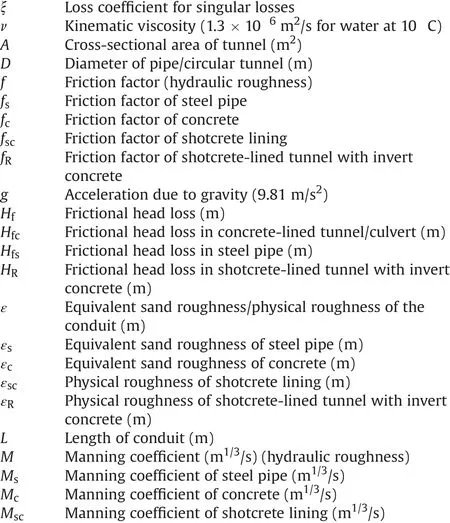
Notations
Adams T,Grant C,Watson H.A simple algorithm to relate measured surface roughness to equivalent sand-grain roughness.International Journal of Mechanical Engineering and Mechatronics 2012;1(2):66-71.
Benson R.Design of unlined and lined pressure tunnels.Tunneling and Underground Space Technology 1989;4(2):155-70.
Bishwakarma MB.Computation of head losses in hydropower tunnels.Dam Engineering 2012;23(2):1-15.
Brekke TL,Ripley B.Design guidelines for pressure tunnels and shafts.1987.Research Project 1745-17,EPRI,Section 5-Detailed design.Technical Report.
Broch E.The development of unlined pressure shafts and tunnels in Norway.In:ISRM international symposium.International society for rock mechanics;1982.
Bruland A,Solvik Ø.Analysis of roughness in unlined tunnels.In:Proceedings of the international conference on underground hydropower plants;1987.p.22-5.
Chilime Hydropower Company Ltd.(CHC).Project completion report.CHC;2005.
Colebrook CF.The flow of water in unlined,limed and partly lined rock tunnels.Proceedings of the Institution of Civil Engineers 1958;11(1):103-32.
Cuesta L.Unlined hydroelectric tunnels.In:ISRM international symposium.Isrm;1988.
Hager WH.Wastewater hydraulics:theory and practice.Springer;2010.
Hákonardóttir KM,Tómasson GG,Kaelin J,Stefánsson B.The hydraulic roughness of unlined and shotcreted TBM-bored tunnels in volcanic rock:In Situ observations and measurements at Kárahnjúkar Iceland.Tunnelling and Underground Space Technology 2009;24(6):706-15.
Huval CJ.Hydraulic design of unlined rock tunnels.Journal of the Hydraulics Division 1969;95(4):1235-46.
Himal Hydro.Archive of the present market rate of tunneling works in the Himalaya.Himal Hydro and General Construction Ltd.;2016.
Kim Y.Tunnel contour quality index in a drill and blast tunnel:definition,analysis and effects.Norwegian University of Science and Technology;2009.PhD Thesis.
Kim Y,Bruland A.A study on the establishment of tunnel contour quality index considering construction cost.Tunnelling and Underground Space Technology 2015;50:218-25.
Lysne DK,Glover B,Støle H,Tesaker E.Hydraulic design.Department of hydraulic and environmental engineering.Norwegian University of Science and Technology;2003.
Maerz N,Ibarra J,Franklin J.Overbreak and underbreak in underground openings,Part 1:measurement using the light sectioning method and digital image processing.Geotechnical&Geological Engineering 1996;14(4):307-23.
Mandal S,Singh M.Evaluating extent and causes of overbreak in tunnels.Tunnelling and Underground Space Technology 2009;24(1):22-36.
Mosonyi E.Water power development.Akademiai Kiado;1965.
Nilsen B,Thidemann A.Rock engineering.Division of Hydraulic Engineering,Norwegian Institute of Technology;1993.
Panthi KK.Evaluation of rock bursting phenomena in a tunnel in the Himalayas.Bulletin of Engineering Geology and the Environment 2012;71(4):761-9.
Panthi KK.Himalayan rock mass and possibility of limiting concrete-lined pressure tunnel length in hydropower projects in the Himalaya.Geosystem Engineering 2015;18(1):45-50.
Pegram GGS,Pennington MS.Hydraulic roughness of bored tunnels.Journal of the South African Institution of Civil Engineering 1998;40(4):9-14.
Penche C.Guide on how to develop a small hydropower plant.European Small Hydropower Association;2004.
Priha S.Hydraulic properties of small unlined rock tunnels.Journal of the Hydraulics Division 1969;95(4):1181-210.
Rahm L.Friction losses in Swedish rock tunnels.In:International water power&dam construction;1958.p.457-64.
Reinius E.Head losses in unlined rock tunnels.In:International water power&dam construction;1970.p.246-52.
Ronn P,Skog M.New method for estimation of head loss in unlined water tunnels.In:Proceedings of the 3rd international conference on hydropower.Rotterdam:A.A.Balkema;1997.p.675-82.
Sharma RH.Modi Khola hydroelectric project.Construction report.Himal Hydro and General Construction Ltd.;2001.
Shrestha PK,Panthi KK.Groundwater effect on faulted rock mass:an evaluation of Modi Khola pressure tunnel in the Nepal Himalaya.Rock Mechanics and Rock Engineering 2014;47(3):1021-35.
Solvik O.Unlined tunnel hydraulics.In:Hard rock underground engineering.Olso,Norway:Furuholmen-Astrup Høyer-Selmer(FHS);1984.
Westfall DE.Water conveyance tunnels.In:Tunnel engineering handbook.Springer;1996.p.298-310.
Wright DE.The hydraulic design of unlined and lined-invert rock tunnels.Construction Industry Research and Information Association;1971.
猜你喜欢
杂志排行

Journal of Rock Mechanics and Geotechnical Engineering的其它文章
- Corrigendum to“Back-analysing rock mass modulus from monitoring data of two tunnels in Sydney,Australia”[J Rock Mech Geotech Eng 5(2017)877-891]
- Effects of lime addition on geotechnical properties of sedimentary soil in Curitiba,Brazil
- KIN SP:A boundary element method based code for single pile kinematic bending in layered soil
- Anisotropy effect on strengths of metamorphic rocks
- Investigation of creep behaviours of gypsum specimens with flaws under different uniaxial loads
- Geomechanical characterization of volcanic rocks using empirical systems and data mining techniques