Online calibration of combustion phase in a diesel engine
2017-12-26QingyuanTANPrasadDIVEKARYingTANXiangCHENMingZHENG
Qingyuan TAN,Prasad DIVEKAR,Ying TAN,Xiang CHEN†,Ming ZHENG
1.Department of Electrical and Computer Engineering,University of Windsor,Windsor N9B 3P4,Canada;
2.Department of Mechanical,Automotive&Materials Engineering,University of Windsor,Windsor N9B 3P4,Canada;
3.Department of Electrical and Electronic Engineering,University of Melbourne,Parkville 3010,VIC,Australia
Online calibration of combustion phase in a diesel engine
Qingyuan TAN1,Prasad DIVEKAR2,Ying TAN3,Xiang CHEN1†,Ming ZHENG2
1.Department of Electrical and Computer Engineering,University of Windsor,Windsor N9B 3P4,Canada;
2.Department of Mechanical,Automotive&Materials Engineering,University of Windsor,Windsor N9B 3P4,Canada;
3.Department of Electrical and Electronic Engineering,University of Melbourne,Parkville 3010,VIC,Australia
In this work,an online calibration mechanism is proposed for the combustion phase in a diesel engine.In particular,a simplified event-based engine model,of which the output predicts the optimum combustion phase,is used to aid the calibration,and the model is updated online along with the engine operation to keep the integrity high so as to improve the quality of optimum combustion phase prediction.It is found this mechanism can be applied to develop an online automated calibration process when the engine system shifts to a new operating point.Engine test results are included to demonstrate the effectiveness of the proposed mechanism.
Extremum seeking,event-based model,diesel engine,online optimization,automated calibration
1 Introduction
The calibration of the diesel engine system is essentially a multi-objective optimization problem[1,2].In traditional engine calibration processes,extensive time and efforts have to be invested to derive the steady state look-up tables for on-board actuation during engine operations since the optimum set-points of the actuators vary over the range of engine operation[3,4].Profound knowledge of engine operation principles as well as advanced optimization methods are called in,therefore,to turn the sophisticated engine calibration process into an efficient and inexpensive one.
For an on-road vehicle,depending on the operating condition,the on-board electronic control unit(ECU)assigns the optimal parameter values to the actuators based on the feedback signals retrieved from various sensors.A finite number of the optimal parameters are calibrated off-line and stored inside the look-up table characterized based on engine operating conditions[5].The parameters for the un-calibrated conditions which have not been included inside the look-up table are interpolated using the calibrated parameters. Model based Design of Experiment(DOE)methods[5,6]are usually applied for engine calibration in which a statistical engine model is required for the determination of the optimal parameters at each “engine operating space”grid knot[7],the obtained values are then applied to engine test cells for validation and fine tuning.When the number of parameters to be calibrated is high,the experimental burden required for DOE based calibration would increase significantly.
To reduce the calibration burden,the data-driven optimization method,such as extremum seeking(ES),has been attempted for engine parameter calibration.Compared to the DOE method,the ES approach relies solely on the relationship between the system input and output[8–10],which is essentially a model-free method.Both engine operation and the ES optimization can proceed concurrently which further reduces the strict design requirements proposed in conventional DOE processes.Therefore,ES is a good alternative for solving engine calibration problems.In[11],ES is applied to the calibration of the air-fuel-ratio and the spark advance phase for a spark ignition engine to deliver high Indicated Mean Effective Pressure(IMEP)and low exhaust manifold temperature.In[12],the valve timings and spark trigger timing of a spark ignition engine is calibrated using ES in terms of achieving the best break specific fuel consumption.In[13],the spark timing for an spark ignition engine which runs on ethanol/gasoline blended fuel is calibrated using ES to operate at the best thermal efficiency.However,the work presented in[11–13]are all measurements dependent without taking the advantage of modeling knowledge.
To improve the efficiency of ES applied to engine calibration,a structure which utilizes both the engine model and the measurement is proposed in this paper.A model-data integrated structure is developed for the calibration of the diesel engine combustion phase in order to achieve the best IMEP value.An event-based first-principle engine model is applied in the structure to predict the optimum combustion phase which is later used to reset the ES method when the engine shifts to a new operation point.The ES optimization compensates the influence of external disturbances and model uncertainty.The event-based model is,on the other hand,updated in real time for its parameters in order to keep the model integrity.
The remainder of this paper is organized as follows.Firstly,a model-data integrated structure is introduced.The event-based model as well as the parameter online optimization are then presented.Thereafter,the effectiveness of the online calibration approach is demonstrated using engine test results.Finally,concluding remarks are made.
2 Online calibration procedures
The structure for the proposed calibration procedures are shown in Fig.1.υdrepresents the external control inputs that define the engine operating point(determined by different engine load or speed).The model is calibrated simultaneously during the engine operation using ES by tuning the coefficient Chtwhich affects the modeled heat transfer process;ˆpIMEis the IMEP acquired from the engine model;ˆθ∗CA50is the optimum CA50(crank angle for 50%of released accumulated heat)control obtained through gradient descent optimization(GDO)[14]on the engine model;pIMEis the measured IMEP value and θCA50is the CA50 control input applied to the real engine.
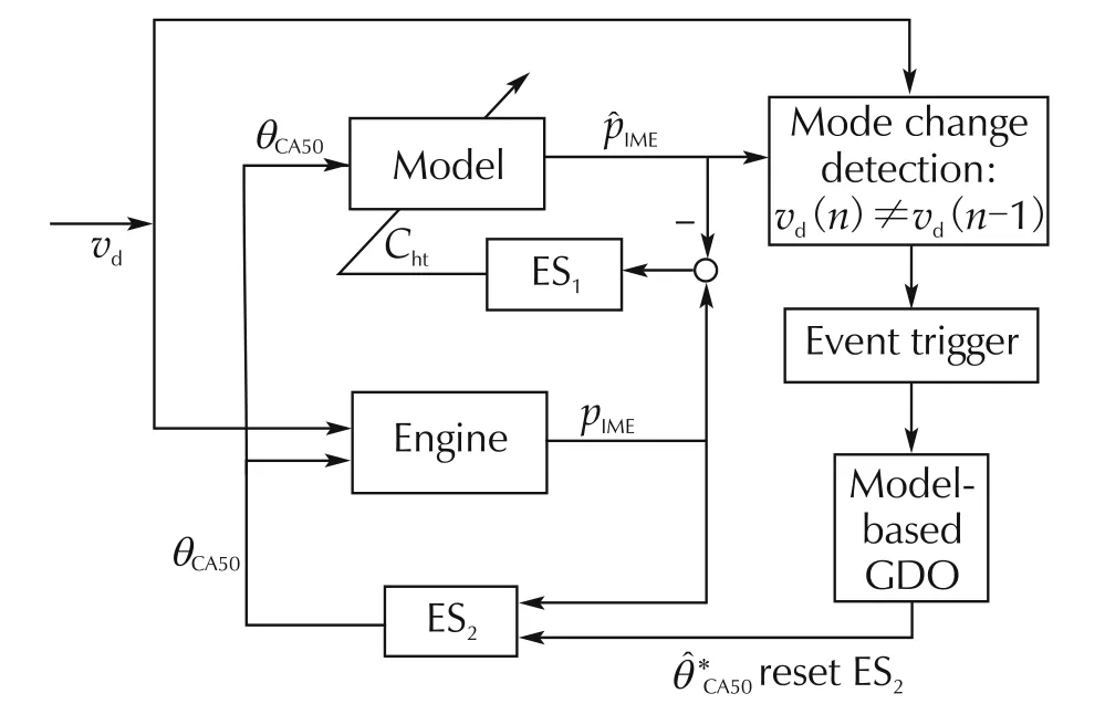
Fig.1 Proposed control structure.
In this work,ES is chosen as the data-driven method.ES is essentially a model-free optimization method which uses input-output measurements to achieve system optimal performances[8,9].As not much knowledge of the system is needed,ES is robust in handling disturbances[8].
ES runs iteratively and the optimization process is to guide the cost function to an extremum(minimum or maximum)by tuning the selected system control input based on the system steady-state response[8].ES would first initiate perturbation on the system input by adding a dither signal to it.The output from the system is used to construct a cost function.The gradient of the cost function can be extracted by ES through demodulation and the interaction with a series of embedded filters.The ES cost function design is based on the assumption that the system output has an asymptotically stable equilibrium.The behavior of the cost function is usually unknown and ES is able to determine the optimum control input from the cost function convergence based on the available measurement data.
In Fig.1,the block ES2represents the ES controller for engine combustion phase calibration.A dither signal with a relatively low frequency is used in order to achieve the time scale separation between the plant dynamics and the ES calibration.By using singular perturbation technique and averaging,ES can estimate the gradient of the cost function[8,9,15].
It is also worthwhile to highlight that modeling work on every automotive subsystems have been immensely investigated[16].These models usually are calibrated by extensive experiments.Even though the accuracy or the complexity of these models do not favor model-based DOE design,some useful system information can be retrieved from the model output.One possible application for these models is to improve the performance of data-driven techniques such as ES.As shown in Fig.1,when the external input υdhas caused a shift of system operation point,i.e.,υd(n)≠ υd(n−1),the“mode change detection”mechanism is triggered.This mechanisminitializes the model-based GDO to obtain the optimum inputunder υd(n)for the model as shown in Fig.1.is then applied as the starting point for ES2to perform the combustion phase calibration.Providing the model is very accurateinitializes ES2to the proximity of the realDuring the calibration,ES2only compensates the effects caused by external disturbances and the model uncertainty.Therefore,the work load on ES calibration is reduced.Note,even ifis faraway fromas the result of bad modeling,which is undesired in real applications,the proposed calibration would perform no worse than the conventional ES calibration.
The authors’have previously investigated the application of ES for online parameter tuning of the event-based engine model[17,18].In this work,the authors have strived an attempt to apply this technique by integrating it into the engine calibration procedures,Fig.1.Real time engine measurement data are acquired for model parameter corrections.The minimization of the differences between measurement and model output are used for this parameter optimization.In Fig.1,ES1indicates the ES block for model parameter optimization.In this work,only Chtis tuned by ES1while guidelines based on experience and literature review are used to select the other parameters of the event-based model.
3 Online optimization of engine model parameters
3.1 Event-based engine model
In this work,the model shown in Fig.1 is a first principle event-based model defined in the engine crank angle domain,θ.The model control input is chosen as the crank angle of 50%accumulated heat release,θCA50,within one engine cycle.The control of θCA50is implemented through the manipulation of fuel injection timing.The parameter identified for online tuning is chosen as Cht.Chtis a heat transfer coefficient defined in the Woschni’s heat transfer correlation[19].A brief introduction of this model is explained further below.Detail explanation and the validation of this model can be found in[17].
Thermodynamic expressions under the crank angle domain for bulk gas temperature T in the nth engine cycle can be represented as

where αis an empirical coefficient that is related to the specific heat ratio γ at the temperature Tnand is given by

The speed-density equation is used to evaluate Nimin terms of the intake manifold pressure,pim,intake manifold temperature,Timand the cylinder volumetric efficiency ηV.

where Vsis the cylinder displacement volume.
The specific heat ratio γ(Tn(θ))at temperature Tnis approximated by a linear expression:

where γ(θIVC)is the specific heat ratio obtained at the crank angle of intake valve closing(θIVC),which is considered as a constant in the model,and ρ is an empirical coefficient obtained from engine tests.
The amount of heat transfer,dQht,is modeled using Woschni’s empirical correlation while the heat release rate,dQhr,is estimated using a triangle function in the crank angle,θ,domain.The control input θCA50is incorporated in the definition of dQhr(see[17]for more details).
The amount of heat transfer is defined as

where As(θ)is the exposed combustion surface area at the crank angle θ,Twallis the cylinder wall temperature,Chtis a coefficient that varies under different types of combustion,B is the bore diameter,pnis the in-cylinder pressure,C1is swirl constant,Spis the mean piston speed,C2is combustion constant,and pmotis the cylinder motoring pressure.
The amount of heat release is approximated by
θCDis the combustion duration determined under the crank angle domain,mfuelis the injected fuel mass at each engine cycle,and Hlowis the lower heating value of the fuel.
The piston work dWpvis expressed as

with the cylinder instantaneous volume V calculated from the slider-crank mechanism(see[19]for more details):

where Vcis the clearance volume of the cylinder,l is the connecting rod length,and a is the crank radius.
The pressure pnin the combustion chamber is modeled as

The underlying engine model can then be expressed in state-space by combining(1)–(12):

is the state variable vector.
zn(θ)indicates the performance output vector,and unis θCA50,all in the nth engine cycle.Note that

where dQ(θ,un)=dQhr(θ,un)− dQht(θ).The performance output zn(θ)represents the normalized piston work,obtained at θ.
In this work,the calibration target is to maximize the engine output work for a constant fuel injection duration so as to achieve the best fuel efficiency.The indicated mean effective pressure or IMEP of the nth engine cycle is a representation of the indicated torque normalized to the displacement volume,and is defined from the time of intake valve closing,IVC,to exhaust valve opening,EVO:

3.2 Online parameter optimization
ES is applied for parameter online optimization.The differences between the realtime engine measured IMEP and the modeled IMEP values are used to form the cost function:

In the event-based model,the simplification for the amount of heat release,dQhr,and the specific heat ratio,γ,would introduce uncertainty to the engine model.The combustion of in-cylinder air-fuel mixture is a complicated thermodynamic process.It determines the amount of energy which is converted from heat to piston work.A good estimation of piston work increases the accuracy for the estimation ofˆpIMEat the end of the nth engine cycle.
As mentioned in the previous section,Chtis a coefficient which affects the modeled in-cylinder combustion characteristics.This coefficient is also dependent on different engine operating conditions.In this work,Chtis tuned for model accuracy improvement,as it determines the amount of heat that is transferred to the cylinder wall.The heat loss reduces the amount of energy which eventually converts to the piston work and therefore lowers down the IMEP value.
4 Engine test setup
The experimental work is conducted on a single cylinder common-rail direct-injection diesel engine with independent air and fuel management systems.The engine details are summarized in Table 1.A non-motoring eddy current dynamometer is used for engine speed control and power dissipation.The engine speed control is set at 1500r·min−1for all the tests.The boosted intake air for the research cylinder is simulated using hydrocarbon-free,dry,compressed air.The air flow rate is measured using a Roots air flow meter.Exhaust gas recirculation(EGR)is adjusted by a combination of EGR valve and exhaust back-pressure valve position.The engine coolant temperature is managed with external conditioning systems to maintain coolant temperature at 80°C.The engine fuel system consists of a high pressure common rail diesel injection with rail pressure up to 1600bar.The average diesel fuel flow rate is measured using volumetric fuel flow detector.

Table 1 Engine system configuration.
5 Engine test results
Engine tests are carried out in the authors’lab to demonstrate the performance of the proposed calibration procedures.In this section,the tuning of heat transfer coefficient,Cht,is first demonstrated.Note that this process runs continuously in real test conditions as to make sure that the modeled IMEP can track the measured IMEP during engine calibration.When the engine shifts to a new operating point,i.e.,υd(n)≠ υd(n− 1),GDO is applied to the optimized event-based model so as to locate the optimumwith the condition of meeting the optimum thermal efficiency demand. Lastly,is applied to reset the ES controller designed for engine combustion phase calibration. In this work,θCA50is chosen as the only control input to be calibrated.A cost function is designed for the calibration of θCA50using ES which starts from
5.1 Online optimization of heat transfer coefficient
The engine operation zone is governed by the engine load and the engine speed. For the engine test conducted in the authors’lab,the engine speed is kept constant at 1500r·min−1using the eddy current dynamometer.The engine load can be adjusted by altering the injection duration.When constant fuel pressure is maintained,a longer injection duration usually results in more fuel spray into the engine cylinder.
As shown in Fig.2,during the engine test,the injection duration is altered from 500μs to 450μs at the 43rd engine cycle.This change has led to a decrease in engine IMEP from around 5.5bar to nearly 4bar.The change in engine operation zone requires a calibration in Chtvalue to maintain a good prediction of IMEP values from the engine model.ES increases Chtto drive(17)to its minimum.
From Fig.2,it is clear that the model tracks the engine measured IMEP quite well as the average difference between the two sets of IMEP values is 0.17bar.The maximum difference between model and the measured IMEP takes place at the time of engine operation zone shifts.Where the difference is 0.98bar.ES responds to this sharp change of cost function values by increasing the Chtvalues drastically.
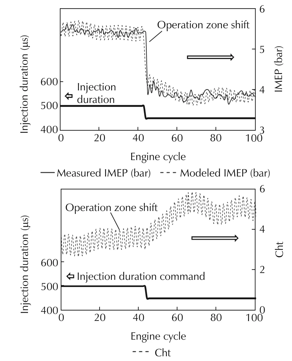
Fig.2 Parameter optimization.
Note that when the engine is operated within each operation zone,Chtis still altered by ES as to minimize the cost function(17).For this test,when the injection duration is 500μs,Chtis 3.7±0.5.When the injection duration is kept at 450μs,Chtis 4.8±0.6.Though variations do exist for Chtvalues within the same operation zone,the differences of Chtobtained under different operation zones are more significant.
5.2 Model input calibration
A simple GDO method is applied to find the optimumfor the event-based model after the injection duration has changed to 500μs:


When the fuel injection duration is kept constant,the minimization of J2is realized by varying thethrough the scheduling of injection timing.As the derived J2value reaches its minimum,the GDO locates thewhich makespˆIMEto its maximum.Thus the event-based engine model can produce the best fuel efficiency.
As shown in Fig.3,the searching forstarts at 364°CA where the modeled IMEP is 5.1bar.The equivalent fuel injection duration is 500μs.GDO delays theas the IMEP increases and the value of J2is reduced.When J2reaches its minimum,GDO terminates andis 369°CA.Thus 369°CA is considered asfor this operation point.The modeled IMEP is around 5.4bar which is close to a 6%increase as comparedto the condition whenis364°CA.ThisGDO calibration lasts for 4ms.

Fig.3 GDO calibration results.
In the following section,the derivedˆθCA50is applied to reset the ES calibration for engine θCA50control at 500μs injection duration.
5.3 Combustion phase calibration
In this section,two engine tests results are demonstrated as to compare the differences between the data only and the proposed procedures for calibrating the engine combustion phase
The injection duration is maintained at 500 μs thus the engine can stay at an IMEP close to 5.2bar.One engine test is conducted using the conventional ES controller to identifywhile the other test uses the proposed approach forsearching.The same cost function(19),which is designed for GDO,is also applied to obtain(pIMEis used to replace).Results from both engine tests are shown in Fig.4.A quick impression from the two results is that despite the ES searching starting point,the obtainedfrom the two tests are both 369°CA.
Fig.4(a)shows the engine test results using the conventional ES approach.Due to the lack of system information,the starting point for this calibration is chosen randomly at 377°CA.Since the delayed phase has caused the combustion to take place more in the engine expansion stroke,the energy can not be used efficiently to convert to piston work.As a result,the obtained IMEP value is low.Based on the measured information,the ES controller drives the θCA50value earlier which eventually rested at 369°CA.The measured IMEP value is around 5.5bar and the overall time consumed for this convergence is around 750 engine cycles.
Fig.4(b)shows the engine test results using the proposed approach.As shown previously,the online optimized model has an optimumof 369°CA when the injection duration is kept at 500μs.Therefore,369°CA is directly applied to initialize the ES controller for θCA50calibration.Note that for this very test demonstrated in Fig.4(b),thehappens to be the same as θ∗CA50for the real engine,thus little effort on the ES searching can be observed.The system can generate a 5.5bar IMEP since the very beginning of ES calibration usingtheprovided by the online optimized engine model.
In addition to the test results,the authors would like to address three remarks as future perspectives for the proposed calibration framework:
Remark 1With a slight modification,the proposed procedures can be extended to handle multiple parameters calibration in a diesel engine.Due to its data-driven nature,the procedures can be executed automatically in practice.Compared to the conventional DOE procedures,this can significantly reduce human interferences and time consumption for the engine calibration task.
Remark 2To accommodate the computational resource constraint,the criteria for event-triggered GDO can be appropriately designed.In particular,a user defined bound is set for variations in consecutive updates of the model parameters.Only if the model parameters updates exceed the bound,the GDO calibration of the engine parameters would be initiated.The defined threshold can be used as an additional index to classify engine operating points in this regard.
Remark 3Other system states can also be estimated from the online optimized model.Subject to the application as well as model complexity,this relatively accurate model can be used in model based designs to regulate engine(transient)performances.

Fig.4 Engine test results.
6 Conclusions
This paper presents a model-data integrated structure capable for online engine combustion phase calibration.θCA50is calibrated subject to the engine IMEP under one operation condition.
The parameters of an event-based model which has been developed by the authors is first optimized against the engine measurement data to guarantee a good matching between the model and real engine performance.GDO method is then triggered by a mode change detection mechanism to identify the optimumwhich maximizes the modeled IMEP value.Theis then applied to reset the ES controller for real engine combustion phase calibration.Engine test results demonstrate the effectiveness of the proposed procedures.
[1]L.Guzzella,A.Amstutz.Control of diesel engines.IEEE Control Systems Magazine,1998,18(5):53–71.
[2]G.Zhu,J.Wang,Z.Sun,et al.Tutorial of model-based powertrain and aftertreatment system control design and implementation.Proceedings of the American Control Conference,Chicago:IEEE,2015:2093–2110.
[3]Z.Yang,R.Stobart,E.Winward.Online Adjustment of Start of Injection and Fuel Rail Pressure Based on Combustion Process Parameters of Diesel Engine.SAE Technical paper 2013-01-0315.Detroit:SAE International,2013.
[4]H.Zhao.Advanced Direct Injection Combustion Engine Technologies and Development.Sawston,Cambridge:Woodhead Publishing,2009.
[5]M.Guerrier,P.Cawsey.The development of model based methodologies for gasoline IC engine calibration.SAE Technical paper 2004-01-1466.Detroit:SAE International,2004.
[6]S.Jiang,D.Nutter,A.Gullitti.Implementation of Model-based Calibration for A Gaslone Engine.SAE Technical Paper 2012-01-0722.Detroit:SAE International,2012.
[7]K.Ropke,C.von Essen.DOE in engine development.Quality and Reliability Engineering International,2008,24(6):643–651.
[8]K.B.Ariyur,M.Krstic.Real-time Optimization by Extremum-seeking Control.New Jersey:Wiley,2003.
[9]S.Liu,M.Krstic.Stochastic Averaging and Stochastic Extremum Seeking.London:Springer,2012.
[10]C.Zhang,R.Ordonez.Extremum-seeking Control and Applications.London:Springer,2012.
[11]E.Corti,C.Forte,G.Mancini,et al.Automatic combustion phase calibration with extremum seeking approach. ASME Journal of Engineering for Gas Turbine and Power,2014,136(9):DOI 10.1115/1.4027188.
[12]D.Popovic,M.Jankovic,S.Magner,et al.Extremum seeking methods for optimization of variable cam timing engine operation.IEEE Transactions on Control Systems Technology,2006,14(3):398–407.
[13]E.Hellstrom,D.Lee,L.Jiang,et al.On-board calibration of spark timing by extremum seeking for flex-fuel engines.IEEE Transactions on Control Systems Technology.2013,21(6):2273–2279.
[14]M.Bartholomew-Biggs.Nonlinear Optimization with Engineering Applications.London:Springer,2008.
[15]S.Z.Khong,Y.Tan,C.Manzie,et al.Multi-agent seeking via discrete-time extremum seeking control.Automatica,2014,50(9):2312–2320.
[16]L.Guzzella,C.Onder.Introduction to Modeling and Control of Internal Combustion Engine Systems.Berlin:Springer,2010.
[17]P.Divekar,Q.Tan,Y.Tan,et al.Nonlinear model reference observer design for feedback control of a low temperature combustion diesel engine.Proceedings of the American Control Conference,Chicago:IEEE,2015:13–18.
[18]Q.Tan,P.Divekar,Y.Tan,et al.A diesel engine combustion phasing optimization using a model guided extremum seeking approach.Chinese Control Conference,Chengdu:IEEE,2016:2837–2842.
[19]J.B.Heywood.Internal Combustion Engines Fundamentals.New York:Mc Graw Hill,1988.
2 December 2016;revised 9 February 2017;accepted 9 February 2017
DOI10.1007/s11768-017-6178-y
†Corresponding author.
E-mail:xchen@uwindsor.ca.
The work at the Clean Combustion Engine Laboratory was supported by the Canada Research Chair program,NSERC,CFI,OIT,AUTO21,the University of Windsor,Ford Motor Company,and other OEMs.
©2017 South China University of Technology,Academy of Mathematics and Systems Science,CAS,and Springer-Verlag Berlin Heidelberg

Qingyuan TANreceived his B.Eng.degree in Instrumentation and Control Science from Shanghai Jiao Tong University,China,and his M.Sc.degree in Bio Microfluidics from University of Toronto,Canada.He is currently a Ph.D.candidate at the University of Windsor,Canada.E-mail:tan1b@uwindsor.ca.

Prasad DIVEKARreceived the B.Sc.degree from the Shivaji University,India,in 2008,the M.S.degree from the Clemson University,U.S.A.,in 2010,and the Ph.D.degree from the University of Windsor,Canada in 2016,all in Automotive Engineering.E-mail:divekar@uwindsor.ca.

Ying TANis an Associate Professor and Reader in the Department of Electrical and Electronic Engineering at The University of Melbourne.She received her B.Sc.degree from Tianjin University,China,in 1995,and her Ph.D.from the National University of Singapore in 2002.She joined McMaster University in 2002 as a postdoctoral fellow in the Department of Chemical Engineering.She joined the Department of Electrical and Electronic Engineering Department at the University of Melbourne in 2004.E-mail:yingt@unimelb.edu.au.

Ming ZHENGis a Professor and Research Chair in Clean Diesel Engine Technology at the University of Windsor.He is the cofounder and the Director of the Clean Combustion Engine Lab.His research areas encompass Clean combustion including diesel combustion,low temperature combustion,diesel HCCI and PCCI,adaptive combustion control,high energy spark ignition and control,EGR hydrogen-reforming,active flow control aftertreatment,engine modeling,diagnosis,and dynamometer tests,biofuel and biodiesel research.E-mail:mzheng@uwindsor.ca.

Xiang CHENis a Professor in the Department of Electrical and Computer Engineering at the University of Windsor.He re-ceived the M.Sc.and Ph.D.degrees from the Louisiana State University,U.S.A.,in 1996 and 1998,respectively.His research areas include Network based control system,robust and nonlinear control,vision based motion control,control applications in automotive and manufacturing systems.E-mail:xchen@uwindsor.ca.
杂志排行

Control Theory and Technology的其它文章
- Towards to dynamic optimal control for large-scale distributed systems
- Comparison of generalized engine control and MPC based on maximum principle
- MPC-based torque control of permanent magnet synchronous motor for electric vehicles via switching optimization
- Optimal heat release shaping in a reactivity controlled compression ignition(RCCI)engine
- Two-degree-of-freedom H-infinity control of combustion in diesel engine using a discrete dynamics model
- Experimental investigation of control updating period monitoring in industrial PLC-based fast MPC:Application to the constrained control of a cryogenic refrigerator