Control method for multi-input multi-output non-Gaussian random vibration test with cross spectra consideration
2017-12-22RonghuiZHENGHuaihaiCHENXudongHE
Ronghui ZHENG,Huaihai CHEN,Xudong HE
State Key Laboratory of Mechanics and Control of Mechanical Structures,Nanjing University of Aeronautics and Astronautics,Nanjing 210016,China
Control method for multi-input multi-output non-Gaussian random vibration test with cross spectra consideration
Ronghui ZHENG,Huaihai CHEN*,Xudong HE
State Key Laboratory of Mechanics and Control of Mechanical Structures,Nanjing University of Aeronautics and Astronautics,Nanjing 210016,China
Cross spectra; Kurtosis control; Multi-input multi-output; Non-Gaussian; Random vibration test
A control method for Multi-Input Multi-Output(MIMO)non-Gaussian random vibration test with cross spectra consideration is proposed in the paper.The aim of the proposed control method is to replicate the speci fied references composed of auto spectral densities,cross spectral densities and kurtoses on the test article in the laboratory.It is found that the cross spectral densities will bring intractable coupling problems and induce dif ficulty for the control of the multioutput kurtoses.Hence,a sequential phase modi fication method is put forward to solve the coupling problems in multi-input multi-output non-Gaussian random vibration test.To achieve the speci fied responses,an improved zero memory nonlinear transformation is utilized first to modify the Fourier phases of the signals with sequential phase modi fication method to obtain one frame reference response signals which satisfy the reference spectra and reference kurtoses.Then,an inverse system method is used in frequency domain to obtain the continuous stationary drive signals.At the same time,the matrix power control algorithm is utilized to control the spectra and kurtoses of the response signals further.At the end of the paper,a simulation example with a cantilever beam and a vibration shaker test are implemented and the results support the proposed method very well.
1.Introduction
The traditional Multi-Input Multi-Output(MIMO)random vibration test is mainly to force the multiple outputs to have the speci fied reference power spectra and the test can only be used for the case of stationary Gaussian random vibration.However,non-Gaussian random vibration environments,such as the action of atmospheric turbulence on aircraft,the acoustic excitation by reaction engine and the vibration by combustion instability,are often encountered in aerospace engineering.It is important to monitor the dynamic behavior of the aerospace structures in these non-Gaussian vibration environments.Furthermore,a structure exposure of the same spectra by the Gaussian vibrations or non-Gaussian vibrations will have different damages.1–4Hence,it is necessary to research the method for MIMO non-Gaussian vibration environmental test.
In recent years,method for the simulation of non-Gaussian random signal has become one of the important topics in many fields,especially in the simulation of wind forces,radar clutters,sea waves and road vehicle vibrations.5–10Some methods are used such as Zero Memory NonLinear(ZMNL)transformation,Auto Regressive Moving Average(ARMA)models,filtered Poisson process,phase modification,alpha stable process,and spherically invariant random vectors process.In the random vibration environmental test,the ZMNL transformation and phase modification are most widely applied.11–13
ZMNL transformation method is based on ZMNL monotonic functions,among which the most classical one is Hermitian polynomial.Wint´erstein developed a Hermitian moment model to transform a Gaussian process into a non-Gaussian process.14But this method has some inherent shortcomings and some modified forms are suggested by other scholars later.15Smallwood presented three kinds of the ZMNL functions,and each covers similar but slightly different ranges of skewness and kurtosis.11The ZMNL transformation method is simple and computationally efficient,but it may induce harmonic distortion and significant dynamic range loss.11,16
Phase modification is also a commonly used method to generate non-Gaussian random vibration signals.It is noted that the Auto Spectral Density(ASD)of a random vibration signal is only related to the amplitudes of its Fourier spectrum;hence the kurtosis of the signal can be adjusted by modifying the phase angles without changing its ASD.Steinwolf gave an analytic phase modification formula to generate a non-Gaussian signal with a specified kurtosis from a Gaussian signal.17,18Smallwood utilized a non-uniform phase distribution method to realize the non-Gaussian signal with specified skewness and kurtosis and only kurtosis greater than or equal to 3 can be produced by the method.19Seong and Peterka constructed the Fourier phases by using the four parameterized phase angles.20Hsueh and Hamernik set the Fourier phase to zero within the selected band of frequencies to synthesize the non-Gaussian signal.21Generally,phase modi fication method is a good technique to generate non-Gaussian random signal,but its computational efficiency is not very well if the speci fied kurtosis is large.
Single Input Single Output(SISO)random vibration test has been widely performed in the laboratory for tens of years.But it is recognized that SISO test is inadequate to simulate the multi-dimensional vibration environments in the real fields.22,23MIMO random vibration test has been emerging and applied along with the advancement of hardware and software.Compared to SISO test,it is much dif ficult to generate the drive signals in MIMO test.Smallwood and Paez contributed to some methods for the generation of stationary Gaussian random drive signals for MIMO test.24But the methodsare difficultto be extended to the MIMO non-Gaussian case.25,26The spectra and kurtoses of the responses should be controlled simultaneously in an MIMO non-Gaussian random vibration test.The kurtoses are used to measure the amplitude distribution characteristics of the responses in time domain and the spectra are used to represent the vibration intensity in frequency domain.Note that the signal in random vibration test is always set to be zero-mean and zero-skewness,so in this paper we only use kurtosis to describe the non-Gaussian characteristic of a random signal.
In some circumstances,the reference spectra are only de fined as a diagonal matrix of auto spectral densities in an MIMO random vibration test.22In such cases,MIMO random vibration test becomes relatively simple,because only the auto spectral densities need to be controlled and the intractable coupling problems induced by cross spectral densities need not to be considered.26But,the cross spectral densities are very important and they determine the phase and coherence relationships among the outputs.So,the cross spectral densities should also be controlled in order to simulate the vibration environments more realistically.However,in MIMO case,the control to non-Gaussian random vibration test will become very dif ficult if the cross spectral densities are taken into account.Thus,the authors aim to solve this problem in the paper.
2.Generation of non-Gaussian random signal
It is known that a Gaussian signal and a non-Gaussian signal can have the same ASD but different kurtoses.As shown in Fig.1,three random signals have the same ASD but different kurtoses.
Zero-mean stationary Gaussian random signal can be completely determined by its standard deviation.But for zeromean zero-skewness stationary non-Gaussian signal,kurtosis must also be taken into consideration.Normalized kurtosis is de fined as the fourth statistical moment divided by the square of the second statistical moment as
where x(t)is a random signal.With this definition,the kurtosis of a Gaussian signal is equal to 3 and the kurtosis of a non-Gaussian signal is not equal to 3.Random signal with a kurtosis greater than 3 is said to be leptokurtic or super-Gaussian and random signal with a kurtosis less than 3 is said to be platykurtic or sub-Gaussian.Because moment higher than the fourth is difficult to estimate,kurtosis is always the only parameter used to measure the non-Gaussian characteristic of a random signal in the engineering practice.
As mentioned above,a non-Gaussian signal can be generated from a Gaussian signal by the ZMNL transformation method.Here,we suggest an improved ZMNL transformation method in order to overcome the defects from the original one.The improved ZMNL transformation method is based on a ZMNL function as
where g(x)is the resulted non-Gaussian signal and x is the Gaussian signal.The constants a and b are selected to control the skewness and kurtosis of g(x).When a=b,skewness is equal to zero.K represents the kurtosis range of g(x).This improved method should be performed in an iterative process to search a set of proper a and b to obtain a desired kurtosis.At the same time,we back-substitute the Fourier amplitudes of the ZMNL transformed signal with its original ones,which will guarantee the Fourier spectrum of the signal not to be changed.With the improved ZMNL transformation method,the defects of the spectrum distortion and dynamic range loss by the original method can be overcome.
The schematic of the improved ZMNL transformation method is shown in Fig.2.The Gaussian random signal is transformed to desired non-Gaussian random signal with the reference kurtosis Kfand tolerance kurtosis Ktolin an iterative process,where Eq.(2)is used in the ZMNL transformation.
3.Description of reference spectra
In MIMO random vibration test,not only the auto spectral densities need to be controlled,but also the cross spectral densities should be considered.The reference spectra matrix should be positive de finite or positive semi-de finite to be physically realizable.In general,in MIMO random vibration test,the reference spectra matrix is a positive de finite Hermitian matrix whose diagonal elements are real positive numbers and the corresponding off-diagonal elements are complex conjugate pairs.
For a linear time invariant system with n excitations and n responses,the positive de finite three-dimensional reference spectral density matrix can be expressed as
where Rjj(j=1,2,...,n)are the auto spectral densities and Rjk(j,k=1,2,...,n,j≠k)are the cross spectral densities.For convenience and brevity,the frequency notation ω will be omitted in the following expressions.The cross spectral densities can be de fined by the auto spectral densities as
From the fact that the reference matrix should be positive de finite,the mathematical constraint conditions for positive de finite matrix R at each frequency line can be expressed as
where Dkis the kth order principal minor determinant of R.Considering the general case that n=3,one can have
Substituting Eqs.(4)and(5)into inequalities(7),one can obtain
The former two inequalities in Eq.(8)are always true,and only the last inequality is required.Therefore,a reasonable set of coherences and phases is needed to make the reference spectra positive de finite.If the reference spectra are originated from the field measured data,there is no such concern because the reference spectra are always physically realizable.If we arti ficially de fine the reference spectra with coherences and phases as a function of frequency,the mathematical constraint conditions should be complied with.
4.Control method
The goal of MIMO non-Gaussian random vibration test is to control the kurtoses and the spectra of the response outputs to meet the references within speci fied tolerances.For a linear time invariant system with n excitations and n responses,we let
where P is a diagonal matrix named random phase matrix,whose the jth diagonal element is eiθj(j=1,2,...,n)and the phase angle θjis uniformly distributed –π to π.L is the Cholesky decomposition of R as
where the superscript ‘H’represents the complex conjugate transpose.
Then one frame Gaussian random signal u can be achieved from U by IFFT,and the jth element of u can be expressed as24
where F-1denotes IFFT and ljkis the element of L.The next step is to use the improved ZMNL transformation method as described in Section 2 and to modify the phase angles θj(j=1,2,...,n)in sequence to achieve one frame reference response signals unwith desired kurtoses.
For simplicity and without loss of generality,we can describe the process in detail with n=2.When n=2,from Eqs.(9)and(11),one can have
We first modify θ1to make the kurtosis of the first output(Line 1 in Eq.(13))meet its reference kurtosis,and then we modify θ2to make the kurtosis of the second output(Line 2 in Eq.(13))meet its reference.Note that the kurtosis of the first output is only affected by θ1and the kurtosis of the second output is affected by θ1and θ2,so θ1and θ2must be modi fied in sequence in order to avoid the cross affection between θ1and θ2.We call this method as Sequential Phase Modi fication(SPM)method.When n>2,we can continue to adjust the kurtoses from line 3 to n in sequence in Eq.(13).It is worthy to note that one cannot use the time domain randomization to u to obtain the continuous stationary non-Gaussian random signals25,27,otherwise the cross spectral structure will be destroyed.
Up to now,we have obtained the outputs whose spectra and kurtoses are met to the references.In order to achieve the drive inputs,an inverse system method in the frequency domain is used.The Fourier spectra of reference response signals uncan be written as
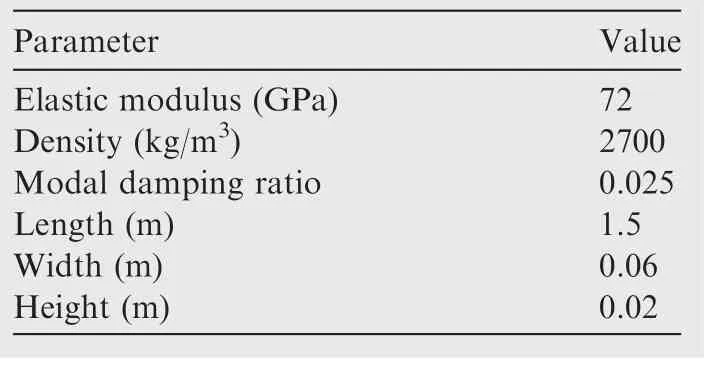
Table 1 Parameters of cantilever beam.
where F denotes FFT.We de fine the frequency response function matrices of the MIMO system as G and its inverse as A.
If G is ill-conditional at some frequencies,the Moore-Penrose pseudo inverse should be used.28,29Then,by the relationship between the outputs and inputs in the frequency domain,the drive spectra matrix can be obtained as
Afterwards,one frame drive signals in time domain can be obtained as
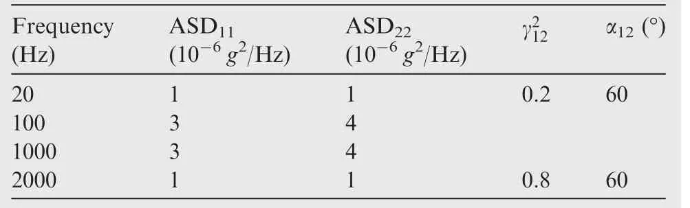
Table 2 Reference spectra for simulation test.

Table 3 Reference kurtoses for simulation test.
Repeat the above steps,and the continuously generated dnare windowed and overlapped to compose the continuous stationary drive signals d.It is obvious that the proposed method is different from time domain randomization technique.The time domain randomization technique uses one frame pseudo random signal to generate continuous stationary drive signals while the proposed method uses continuously generated dnto compose the continuous stationary drive signals by the windowing and overlapping.The function of the windowing and overlapping is to remove the discontinuities at the frame boundaries and to generate real drive signals.Here the Half-Sine window or Potter window with overlap factor of 2 is used to make d stationary and they have a good side lobe decaying.24It should be noted that the windowing and overlapping to a signal will decrease its kurtosis,but this in fluence is linear and does not affect the kurtosis control.30
Because there are many factors which will affect the control process during the test31,one can hardly achieve reasonable responses by one-time inputs.It is essential to correct the drive signals for many times in order to obtain the responses with satisfactory spectra and kurtoses.The control algorithm is used to implement the correction process.Here the matrix power control algorithm is utilized for spectra correction,which has a good stability and does not need scale process.31The two main formulas of matrix power control algorithm are
where Δlis the spectra error,Lris the Cholesky decomposition of the reference spectral density matrix R by Eq.(10)and Lcis the Cholesky decomposition of the spectral density matrix Scof the present responses.Lnewwill be used to substitute L in Eq.(9)to generate new U and Loldis L used in Eq.(9)last time.ε is the spectrum matrix power which is a constant between(0,1].Similarly,a control algorithm for the kurtosis correction is put forward.The two formulas are
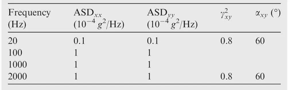
Table 4 Reference spectra for test.

Table 5 Reference kurtoses for test.
where Δkis the kurtoses error,Kris the reference kurtosis matrix which is a diagonal matrix with the reference kurtoses as the diagonal elements,and Kcis the kurtosis matrix of the present responses.Knewwill be used to generate one frame new reference response signals by the improved ZMNL transformation method in Eq.(11)and Koldis used last time.η is the kurtosis matrix power which is a constant between(0,1].
Finally,the block diagram for the control method of MIMO non-Gaussian random vibration test is shown in Fig.3.
5.Numerical example
To verify the effectiveness of the proposed control method given in Fig.3,a simulation test was carried out by an aluminum cantilever beam.The parameters of the beam are listed in Table 1 and the locations of the excitation(input)and control(output)points are shown in Fig.4.Accordingly,the amplitude-frequency diagrams of Frequency Response Functions(FRFs)of the system are exhibited in Fig.5.The control frequency band for simulation was from 20 to 2000 Hz with 400 spectral lines.The reference spectral densities and kurtoses were set as described in Table 2 and Table 3 respectively.Only values at the break points are given and values at other frequency points are calculated by the linear logarithmic interpolation with the given values.
The uncontrolled response spectra of two control points are shown in Fig.6.From Fig.6,we can see that the uncontrolled response spectra exceed the reference spectra at some frequencies because of the relatively large conditions of the FRF matrices at these frequency points,which make large errors during the inverse calculation of the FRF matrix.Fig.7 shows the controlled response spectra.It can be seen that the response spectra have been controlled within the±3 dB alarm limits after recurrent correction of the drive signals three times.Fig.8 shows the controlled response kurtoses.It is clearly to be seen that the kurtoses of the response signals have been stably controlled toward or around the reference values.The segment time histories of the drive signals and response signals are shown in Figs.9 and 10 respectively.
6.Test
6.1.Parameter setting
To verify the feasibility of the proposed control method for MIMO non-Gaussian random vibration test,a two-input two-output test was carried out.A personal computer with the programmed control software and an Agilent VXI were used to control the x and y directions of a three-axis vibration shaker table.The test system is shown in Fig.11 and the amplitude-frequency diagrams of frequency response functions of the system are exhibited in Fig.12.The control frequency band was from 20 to 2000 Hz with 400 spectral lines.The reference spectral densities were de fined in Table 4 and reference kurtoses for two directions were given in Table 5.For the reference spectra in Table 4,only values at the break points were given and values at other frequency points were calculated by the linear logarithmic interpolation with the given values.The tolerances for the test were set as follows.
(1)Auto spectral densities:set±3 dB as alarm limits and±6 dB as abort limits in all bandwidths.The relative error of the Root Mean Square(RMS)value of response acceleration at each controlled point should be within±10%according to its reference.
(2)Cross spectral densities:
(A)Coherence:set the tolerance to be±0.1 in the rangeand others are not set in this paper.
(B)Phase:set the tolerance to be±10°in the range 0.5any phase is acceptable.
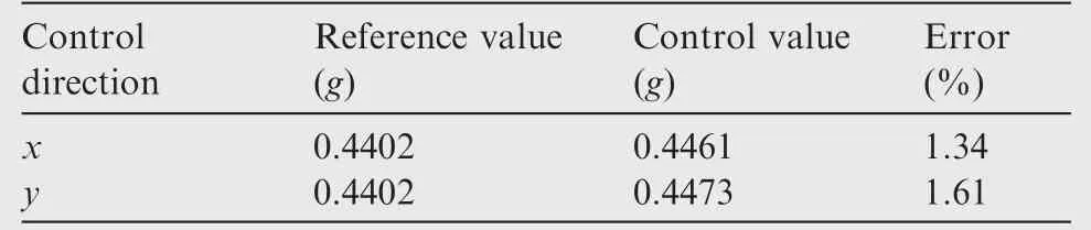
(3)Kurtoses:set the tolerance to be±1 in the range K>3 and±0.5 in the range 0 As shown in Fig.13,the uncontrolled response spectra deviate from the references largely.The uncontrolled auto spectra are not completely within the±3 dB alarm limits and even some spectral lines are beyond the±6 dB abort limits at the frequency points about 1265 and 1675 Hz.It can be seen from Fig.12 that 1265 and 1675 Hz are the resonance peaks of the FRFs,which lead to errors in the inverse calculation of the FRF matrices.From Fig.13,we can also see that the uncontrolled coherence and phase deviate from the references largely.Fig.14 shows the controlled spectra with four spectral corrections and it can be seen that the spectra are all within the tolerance ranges and very close to the references.The spectral RMS errors between the controlled auto spectra and the references are listed in Table 6.Before the kurtoses corrections,the kurtoses of the response signals were all about 3.Fig.15 shows the kurtosis controlling process.Two segments of the two drive signals and controlled responses are shown in Figs.16 and 17 respectively. Table 6 Spectral RMS errors. In this paper,a control method for MIMO non-Gaussian random vibration test with cross spectra consideration is proposed.The control method is composed of four parts which are the inverse system method,the improved ZMNL method,the sequential phase modi fication method and the matrix power control algorithm. Because of the coupling effects of the cross spectra,it is very difficult to generate the drive signals for the MIMO non-Gaussian random vibration test.The key idea of the inverse system method is to generate the reference response signals from the reference spectra and kurtoses in the time domain first and then to obtain the drive signals by inverse system in the frequency domain.The improved ZMNL method is set forth to adjust a random signal to have a desired kurtosis without dynamic range loss.The sequential phase modification method is introduced to eliminate the cross effects among the phase selections.The matrix power control algorithm is applied to the spectra and kurtoses iteration corrections. At last,the proposed control method is verified by a simulation example with a cantilever beam and a shaker test and the results are satisfactory. This work was supported by the Priority Academic Program Development of Jiangsu Higher Education Institutions and the Postgraduate Research&Practice Innovation Program of Jiangsu Province(No.KYCX17_0234). 1.Sarkani S,Kihl DP,Beach JE.Fatigue of welded joints under narrowband non-Gaussian loadings.Probabilist Eng Mech 1994;9(3):179–90. 2.Benasciutti D,Tovo R.Fatigue life assessment in non-Gaussian random loadings.J Fatigue 2006;28(7):733–46. 3.Kihm F,Rizzi SA,Ferguson NS,Halfpenny A.Understanding how kurtosis is transferred from input acceleration to stress response and its in fluence on fatigue life.11th international conference on recent advances in structural dynamics;2013 July 1–3;Pisa,Italy.Southampton:University of Southampton Press;2013.p.6. 4.Kihm F,Ferguson NS,Antoni J.Fatigue life from kurtosis controlled excitations.Proc Eng 2015;133:698–713. 5.Iii WHC.Comments on kurtosis of military vehicle vibration data.J IES 1991;34(6):38–41. 6.Gioffre`M,Gusella V,Grigoriu M.Simulation of non-Gaussian if eld applied to wind pressure fluctuations.Probabilist Eng Mech 2000;15(4):339–45. 7.Tatarskii VV,Tatarskii VI.Non-Gaussian statistical model of the ocean surface for wave-scattering theories.Waves Random Media 1996;6(4):419–35. 8.Rangaswamy M.Spherically invariant random processes for modeling non-Gaussian radar clutter.1993 conference record of the 27th Asilomar conference on signals,systems and computers.Pacific Grove,USA;Piscataway:IEEE Press;1993.p.1106–10. 9.Rouillard V.On the non-Gaussian nature of random vehicle vibrations.Lecture Notes Eng Comp Sci 2007;2166(1):1219–24. 10.Grigoriu M.Applied non-Gaussian processes:Examples,theory,simulation,linear random vibration,and MATLAB solutions.Upper Saddle River:Prentice Hall;1995.p.1–232. 11.Smallwood DO.Generating non-Gaussian vibration for testing purposes.Sound Vib 2005;39(10):18–24. 12.Steinwolf A.Vibration testing by non-Gaussian random excitations with specified kurtosis.Part I:Discussion and methods.J Test Eval 2014;42(3):659–71. 13.Steinwolf A.Vibration testing by non-Gaussian random excitations with specified kurtosis.Part II:Numerical and experimental results.J Test Eval 2014;42(3):672–86. 14.Wint´erstein SR.Nonlinear vibration models for extremes and fatigue.J Eng Mech 1988;114(10):1772–90. 15.Yang Q,Tian Y.Comparison of non-Gaussian peak factor formulae in wind engineering applications.8th Asia-Pacific conference on wind engineering;2013 Dec 10–14;Chennai,India;Singapore:Research Publishing;2013.p.885–94 16.Baren PV.The missing knob on your random vibration controller.Sound Vib 2005;39(10):10–6. 17.Steinwolf A.Approximation and simulation of probability distributions with a variable kurtosis value.Comput Stat Data An 1996;21(2):163–80. 18.Steinwolf A.Random vibration testing with kurtosis control by IFFT phase manipulation.Mech Syst Signal Pr 2012;28:561–73. 19.Smallwood D.Vibration with non-Gaussian noise.J IEST 2009;52(2):13–30. 20.Seong SH,Peterka JA.Experiments on Fourier phases for synthesis of non-Gaussian spikes in turbulence time series.J Wind Eng Indust Aerodyn 2001;89(5):421–43. 21.Hsueh KD,Hamernik RP.A generalized approach to random noise synthesis:Theory and computer simulation.J Acoust Soc Am 1990;87(3):1207–17. 22.United States Department of Defense.Test method standard for environmental engineering considerations and laboratory tests.Washington,D.C.:United States Department of Defense;2014.Standard No:MIL-STD-810G_CHG-1. 23.Underwood MA,Keller T.Recent system developments for multiactuator vibration control.Sound Vib 2001;35(10):16–23. 24.Smallwood DO,Paez TL.A frequency domain method for the generation of partially coherent normal stationary time domain signals.Shock Vib 1993;1(1):45–53. 25.Chen HH,Wang PY,Sun JY.Generation of multi-input multioutput non-Gaussian driving signal based on inverse system method.Acta Aeronautica etAstronautica Sinica 2016;37(5):1544–51[Chinese]. 26.Zheng R,Chen H,He X.Control method for multiple-input multiple-output non-Gaussian random vibration test.Packag Technol Sci 2017;30(7):331–45. 27.Smallwood DO.Multiple shaker random vibration control—An update.Albuquerque:Sandia NationalLaboratories;1999.Report No.:SAND 98–2044C. 28.Cui S,Chen HH,He XD,Zheng W.Multi-input multi-output random vibration control using Tikhonov filter.Chin J Aeronaut 2016;29(6):1649–63. 29.Cui S,Chen HH,He XD.Time-domain approach for multi-exciter random environment test.J Sound Vib 2017;398:52–69. 30.Jiang Y,Chen X,Tao JY.Study on the generation of super-Gaussian and true-random drive signals using time domain randomization.J Vibr Eng 2005;18(4):491–4. 31.Cui XL,Chen HH,He XD,Jiang SY.Matrix power control algorithm for multi-input multi-output random vibration test.Chin J Aeronaut 2011;24(6):741–8. 28 October 2016;revised 20 June 2017;accepted 11 August 2017 Available online 16 October 2017 Ⓒ2017 Chinese Society of Aeronautics and Astronautics.Production and hosting by Elsevier Ltd.This is an open access a rticle under the CCBY-NC-ND license(http://creativecommons.org/licenses/by-nc-nd/4.0/). *Corresponding author. E-mail addresses:rhzheng@nuaa.edu.cn(R.ZHENG),chhnuaa@nuaa.edu.cn(H.CHEN),hexudong@nuaa.edu.cn(X.HE). Peer review under responsibility of Editorial Committee of CJA.6.2.Test results
7.Conclusions
Acknowledgements
杂志排行

CHINESE JOURNAL OF AERONAUTICS的其它文章
- A general method for closed-loop inverse simulation of helicopter maneuver flight
- Numerical simulation of a cabin ventilation subsystem in a space station oriented real-time system
- Parametric analyses on dynamic stall control of rotor airfoil via synthetic jet
- Effect of particle size and oxygen content on ignition and combustion of aluminum particles
- Effects of axial gap and nozzle distribution on aerodynamic forces of a supersonic partial-admission turbine
- Effect of a transverse plasma jet on a shock wave induced by a ramp