Research on characteristics of integrated type hydraulic transformer’s control angle①
2017-12-19LiuChengqiang刘成强LiuYinshuiJiangJihaiYangGuanzhong
Liu Chengqiang (刘成强), Liu Yinshui , Jiang Jihai*, Yang Guanzhong*
(*School of Mechanical and Electrical Engineering, Xuzhou Institute of Technology, Xuzhou 221018,P.R.China) (**School of Mechanical Science and Engineering, Huazhong University of Science and Technology, Wuhan 430074,P.R.China) (***School of Mechanical and Electrical Engineering, Harbin Institute of Technology, Harbin 150001,P.R.China)
Research on characteristics of integrated type hydraulic transformer’s control angle①
Liu Chengqiang (刘成强)②, Liu Yinshui**, Jiang Jihai***, Yang Guanzhong***
(*School of Mechanical and Electrical Engineering, Xuzhou Institute of Technology, Xuzhou 221018,P.R.China) (**School of Mechanical Science and Engineering, Huazhong University of Science and Technology, Wuhan 430074,P.R.China) (***School of Mechanical and Electrical Engineering, Harbin Institute of Technology, Harbin 150001,P.R.China)
In order to realize remote control of hydraulic transformers and improve the control precision of the pressure ratio, an integrated type electric hydraulic servo hydraulic transformer is proposed in this paper, a mathematical model is built and simulation of electro-hydraulic servo integrated hydraulic transformer’s control angle is carried out, the principle prototype of the transformer is designed and manufactured, and experimental study is carried out on the experimental bench. The experimental results verify the correctness of the mathematical model. The results show that electro hydraulic servo control can improve the accuracy and dynamic response speed of control angle, which provides a reference for the further research of the hydraulic transformers.
electro-hydraulic servo, hydraulic transformer, control angle, simulation, experimental
0 Introduction
With more and more serious environmental pollution, energy saving and emission reduction technology has become a hot research topic. A hydraulic common pressure rail system is an efficient hydraulic transmission system[1], in which the power source is composed of a high pressure oil rail and a low pressure oil rail, and various executive components are connected to the pressure network in parallel, loads obtains power according to their own needs from the power system. The system fully realizes power supply on demand without throttling loss, therefore, it has high efficiency and broad application prospects. In the hydraulic pressure common rail system when the actuator is a hydraulic cylinder, because the hydraulic cylinder’s area is fixed in the process of working, the control of the load can only be controlled by the hydraulic valve, thus throttling loss affects the transmission efficiency of hydraulic common pressure rail system. In order to solve this problem, a hydraulic transformer, a kind of hydraulic component, is developed[2].
Hydraulic transformer can be categorized into tandem type and integrated type according to the structural form. The tandem type is that the hydraulic pump and hydraulic motor are connected directly in series through a spindle, having large volume and weight, slow dynamic response, which limits its application. The integrated hydraulic transformer is formed by processing three valve grooves evenly distributed on the valve plate, first proposed by the Holland Innas company and Noax company[3]. With the characteristics of compact structure, small volume, high efficiency, and fast dynamic response, the integrated type has broad application prospects and become a hot spot of research.
According to the features of the integrated hydraulic transformer, Achten, et al. studied the hydraulic transformer’s valve plate and hydraulic transformer application[4]. Rotation of valve plate caused reduced flow area to generate throttling loss. Transformation factor range of hydraulic transformer is limited due to the small rotation angle of the valve plate. Yang and Xu studied integrated manual hydraulic transformer and its application[5,6], an integrated hydraulic transformer’s principle prototype was designed based on A2F hydraulic motor. In order to avoid throttling loss, the rear end cover of the hydraulic transformer’s valve plate was designed. The application of hydraulic transformer in the hydraulic elevator, shield equipment, drilling machine cutter on the system were studied. The results show that the cutter power system transmission efficiency can be increased by 4.9%[7]. The research of integrated electronic control hydraulic transformer was carried out by Jiang, et al.[8-10], in which electronic control type hydraulic transformer was developed, the remote control of the transformation ratio was realized and the servo motor could directly drive valve disc rotation and a continuous adjustment of the range of 0~2 could be achieved to broaden the scope of the transformer ratio. Zhang, et al. analyzed and studied the hybrid excavator system with hydraulic transformer[11].
Many countries in the world have studied the application of hydraulic transformers, Vael conducted the hydraulic hybrid cars based on hydraulic transformer[12], and test results showed that in the medium car fuel consumption was decreased by 50%, CO2emissions was decreased by 82g/km, much lower than the European emission standards in 2012. In 2014, the United States Caterpillar Inc. applied the hydraulic transformer excavator boom energy recovery system patents[13]. Lee studied the trajectory tracking performance of hydraulic transformer control hydraulic cylinder[14]. Its experimental study has not yet been carried out because the hydraulic transformer’s principle prototype has not been manufactured. In 2015, Danzl, et al. applied for a non-road vehicles hydraulic power system of the invention patent, with the hydraulic transformer to control the power, the power matching of engine could be better[15].
Control angle of hydraulic transformer determines the control performance of hydraulic transformer directly. This paper simulates and experiments on the control performance of hydraulic transformer’s control angle, which has laid a foundation for the research of the integrated hydraulic transformer.
1 Mathematical model of control angle
The integrated electro hydraulic servo hydraulic transformer is composed of a hydraulic swing motor and a servo valve. The structure of integrated electro hydraulic servo of the hydraulic transformer is shown in Fig.1.
The servo amplifier is used for amplifying the control signal, in which the input is the voltage signal, the output is the current signal, and the output current of the servo amplifier is simplified as linear relationship.
i=Kau
(1)
where u is the amplifier input control voltage (V), i is the amplifier output current (A), and Kais the gain of amplifier (A/V).
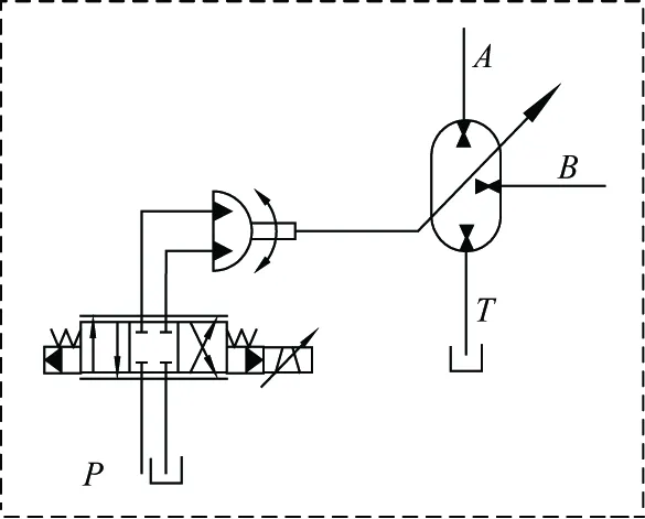
Fig.1 Integrated electro hydraulic servo hydraulic transformer
The electro-hydraulic servo valve is an electro-hydraulic converter and power amplifying element, where the electrical signal is converted into small hydraulic power, and a key component of electro-hydraulic servo control integrated hydraulic transformer, while the servo valve is seen as two order oscillation, when the transfer function is
(2)
where ωsvis equivalent to undamped natural frequency of electro hydraulic servo valve (rad/s), Ksvis no-load flow gain of electro hydraulic servo valve (m3/s·A), ξsvis equivalent to the damping ratio of electro hydraulic servo valve.
The linear flow equation of the valve port of the servo valve is
QL=Kqxv-KcPL
(3)
where Kqis the electro-hydraulic servo valve port flow gain, xvis the spool displacement of the servo valve, QLis the electro-hydraulic servo motor load flow, Kcis the flow of the valve port flow pressure coefficient, and PLis the load side pressure.
The Laplace transform of Eq. (3) is obtained:
QL(s)=KqXv(s)-KcPL(s)
(4)
Flow continuity equation of oscillating hydraulic motor is
(5)
where θcis the control angle of hydraulic transformer, Ctmis the total leakage coefficient of swing hydraulic motor, Dmis the swing displacement of hydraulic motor, Vmis the total volume of swing hydraulic motor, servo valve chamber and connecting pipe, βeis the effective volume elastic modulus of working fluid.
The Laplace transform of Eq.(5) is obtained as
(6)
Neglecting the mass of the oil in the chamber of the hydraulic motor, the torque equation of the main shaft of the hydraulic transformer is obtained:
(7)
where Jmis the total inertia on the motor shaft, Bmis the viscous damping coefficient, G is the spring stiffness of load, TLmis the external load torque on the motor shaft.
The Laplace transform of Eq. (7) is obtained:
DmPL(s)=Jms2Θc(s)+BmsΘc(s)+GΘc(s)+TLm
(8)
The transfer function of the control angle of hydraulic transformer is obtained:
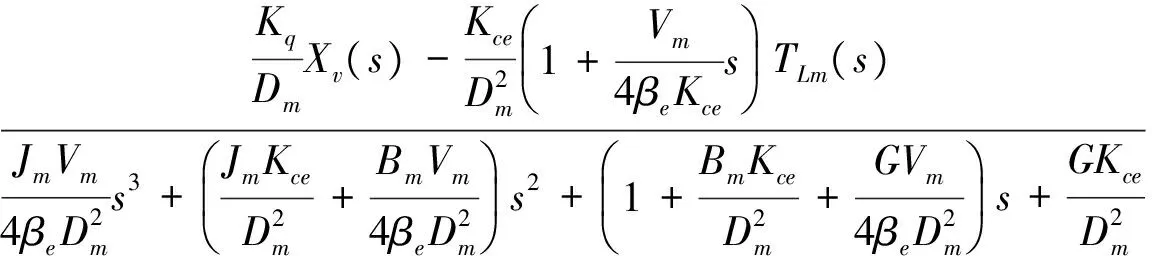
(9)
According to Eq.(9), the transfer function block diagram of electro-hydraulic servo integrated hydraulic transformer’s control angle is shown in Fig.2.
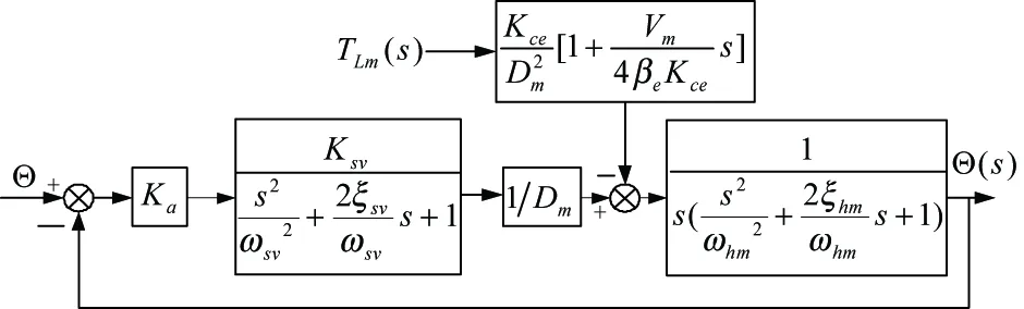
Fig.2 Transfer function block diagram of control angle of hydraulic transformer
2 Simulation research of control angle
According to the transfer function of the hydraulic transformer’s control angle, the simulation is carried out in Matlab. The Bode diagram of hydraulic transformer’s control angle is shown in Fig.3.
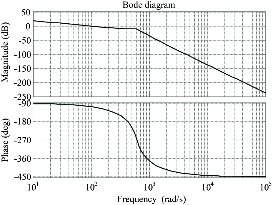
Fig.3 Bode diagram of hydraulic transformer’s control angle
Fig.3 shows that magnitude margin control angle of hydraulic transformer is 9.6dB, phase margin is 74°, the bandwidth of the control system is 94rad/s. The step simulation curves of hydraulic transformer’s angle are shown in Fig.4 and Fig.5, in which 1 is for a given signal, 2 is for tracking signal. The Fig.4 shows that when the amplitude is 50°, the adjusting time is 0.15s, the overshoot is 8%. The Fig.5 shows that when the amplitude is 100°, the adjusting time is 0.4s, the overshoot is 5%. The control angle of integrated type hydraulic transformer has fast dynamic response and small steady state error. The power density of integrated type hydraulic transformer is higher than that of servo motor.
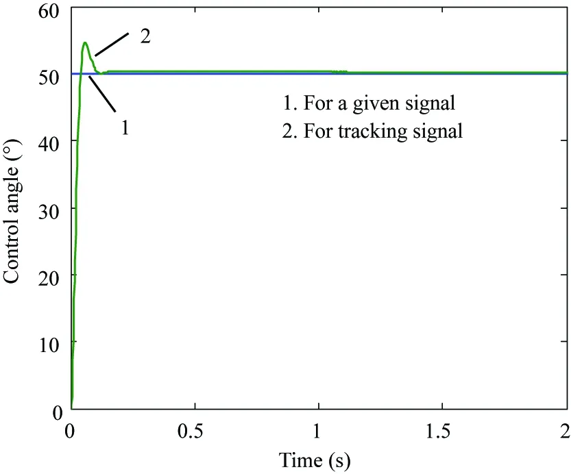
Fig.4 Hydraulic transformer’s control angle step response curve(amplitude 50°)
The slope response simulation curve of hydraulic transformer’s control angle is shown in Fig.6 and Fig.7, 1 for a given signal, 2 for tracking signal. When the slope of ramp signal is 80°/s, the control angle of hydraulic transformer can be tracked well. When the slope of ramp signal is 100°/s, the lag time of hydraulic transformer's control angle is 0.15s, the error of control angle do not continue to expand.
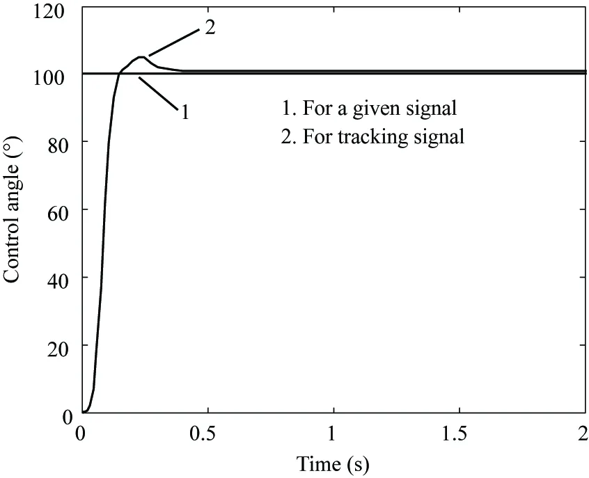
Fig.5 Hydraulic transformer’s control angle step response curve(amplitude 100°)
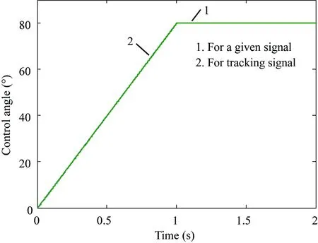
Fig.6 Slope response curve of hydraulic transformer’s control angle(slope 80°/s)
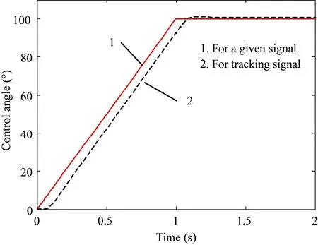
Fig.7 Slope response curve of hydraulic transformer’s control angle(slope 100°/s)
3 Experimental study
In order to carry on the research of the integrated electro hydraulic servo hydraulic transformer, a principle prototype of the integrated hydraulic transformer is designed and built. The experiment platform is built, and the system of the experiment table is shown in Fig.8.
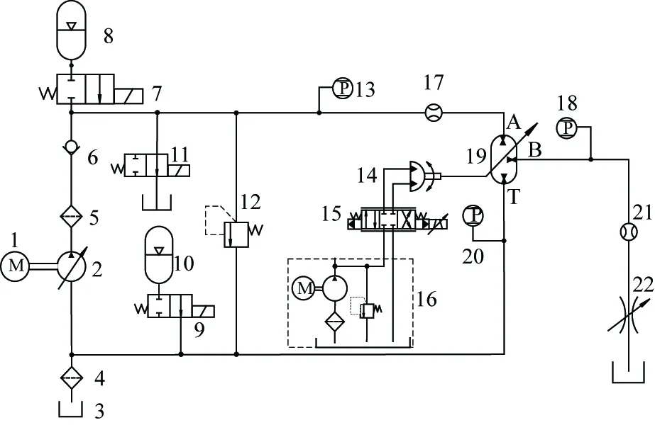
1- motor 2- constant pressure variable pump 3- tank 4, 5- oil filter 6- check valve 7, 9, 11-accumulator safety valve 13, 12- 18, 20- pressure sensor 14-swing hydraulic motor 15-servo valve 16- electro-hydraulic servo oil source 19- hydraulic transformer 22- throttle valve 17,21- flow sensor
Fig.8 Integrated hydraulic transformer test bench
The control program is written based on C++ language, and the experimental study was carried out used PID control strategy. The step response curve of electro-hydraulic servo hydraulic transformer’s control angle is shown in Fig.9 and Fig.10. Fig.9 shows that the adjusted time is 0.4s, steady state error is 2%, overshoot is 10%, when the amplitude is 10°. Fig.10 shows that the adjusted time is 0.7s, steady state error is 0.5%, overshoot is 5%, when the amplitude is 50°. The time lag of the control angle’s step response is about 0.1s, which is caused by inertia of integrated type hydraulic transformer. Steady-state error of hydraulic transformer’s control angle is less than 0.5°, it can improve the control precision of pressure transformer ratio.
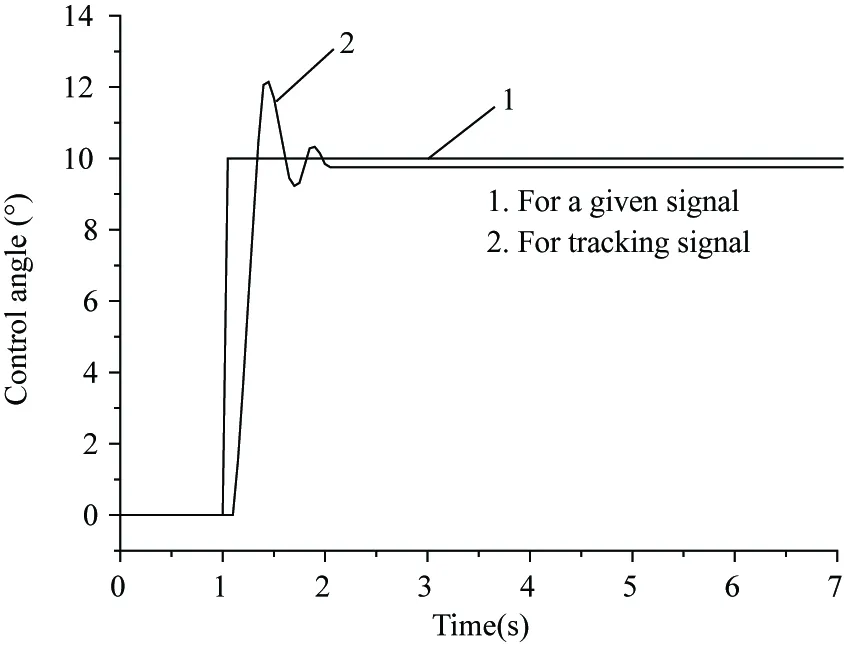
Fig.9 Step response of control angle(amplitude 10°)
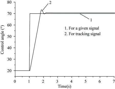
Fig.10 Step response of control angle(amplitude 50°)
The ramp response curves of the hydraulic transformer’s control angle are shown in Fig.11, Fig.12 and Fig.13, in which 1 is the given signal, 2 is the response signal. Fig.11 shows that when the slope of ramp signal is 40°/s the control angle can be well tracked. Fig.12 shows that when the slope is 70°/s the error of control angle continues to expand. Fig.13shows that when the slope of ramp signal is 0.02°/s the control angle produces crawl phenomenon, which is due to the compressibility of oil and change between static and dynamic friction, and the error within 0.03°.
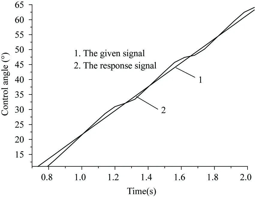
Fig.11 Slope response of control angle (slope 40°/s)
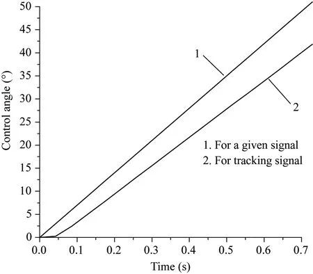
Fig.12 Slope response of control angle (slope 70°/s)
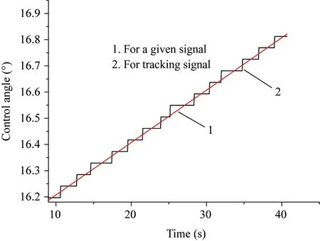
Fig.13 Slope response of control angle (slope 0.02°/s)
4 Conclusion
Electro hydraulic servo integrated hydraulic transformer’s control angle controlled by swing hydraulic motor implementation can achieve remote control of the pressure ratio and improve the control speed and control accuracy of the pressure ratio. Electro hydraulic servo integrated hydraulic transformer’s control angle is able to track the maximum ramp in 70°/s, the control angle step response exists in the time delay of about 0.1s. The experimental results are in agreement with the simulation results, and verify the correctness of the simulation model.
Reference
[ 1] Yang G Z, Jiang J H. Power characteristics of a variable hydraulic transformer. Chinese Journal of Aeronautics. 2015, 28(3):914-931
[ 2] Jiang J H, Lu H Y, Zhou R Y. Development of hydraulic transformer in constant pressure rail system. Journal of Southeat University (Natural Science Edition), 2006, 36(5):869-874
[ 3] Achten P A J, Fu Z, Vael G E. Transforming future hydraulics: a new design of a hydraulic transformer. In: Proceedings of the 5th Scandinavian International Conference on Fluid Power, Linköping, Sweden, 1997. 1-23
[ 4] Achten P A J, Vael G E M, Jeroen Potma, et al. ‘Shuttle’ technology for noise reduction and efficiency improvement of hydrostatic machines. In: Proceedings of the 7th Scandinavian International Conference on Fluid Power, Linköping, Sweden, 2001. 73-83
[ 5] Xu B, Ma J E, Yang H Y. Analysis of instantaneous flow rate character of hydraulic transformer. Journal of Mechanical Engineering, 2007, 43(11):44-49
[ 6] Ouyang X P, Xu B, Yang H Y. Innovation method of widening adjustable pressure range of hydraulic transformers. Journal of Mechanical Engineering, 2004, 40(9):28-32
[ 7] Liu T, Gong G F, Peng Z. Hybrid cutterhead driving system for TBM based on hydraulic transformer. Journal of Zhejiang University (Engineering Science Edition), 2016, 50(2):419-427
[ 8] Zhou R Y, Lu H Y, Liu Y H. Theory analysis and simulation research on the principle of hydraulic transformer. Machine Tools and Hydraulic, 2007, 35(1):103-105
[ 9] Lu H Y, Jiang J H. Study on hydraulic transformer driving linear load system based on fuzzy tuning PID control strategy. Machine Tools and Hydraulic, 2009, 37(1):58-61
[10] Liu C Q, Jiang J H, Gao L X. Valve plate’s buffer slot in electro-hydraulic servo plate-inclined plunger hydraulic transformer. Journal of Harbin Institute of Technology, 2013, 45(7):53-56
[11] Zhang S Z, Deng B, Ke J. Research on energy regeneration system of hydraulic excavator’s boom based on hydraulic transformer. China Mechanical Engineering, 2010, 10:1161-1166
[12] Vael G E M, Achten P A J. IHT controlled serial hydraulic hybrid passenger cars. In: Proceedings of the 7th International Fluid Power Conference, Aachen, Germany, 2010. 200-212
[13] Ma P, Chen D, Zhang J, et al. Hydraulic hybrid boom system hydraulic transformer, US patent: WO 2014/0325972A1, 2014
[14] Lee S, Li P. Trajectory tracking control using a hydraulic transformer. In: Proceedings of the 2014 International Symposium on Flexible Automation, Hyogo, Japan, 2014. 1-8
[15] Danzl P W, Rannow M B, Wang M, et al. Energy recovery system for off-highway vehicles with hydraulic transformer coupled to transmission power take-off. US patent: WO 2015/191661A1, 2014
10.3772/j.issn.1006-6748.2017.04.009
①Supported by the National Natural Science Foundation of China (No. 51575200), State Key Laboratory of Fluid Power Transmission and Control(No. GZKF-2008003), and the Fourteenth Batch of High Level Talents Project of “Six Talents Summit” in Jiangsu (No. JXQC036).
②To whom correspondence should be addressed. E-mail: lcq08@163.com
on Oct. 28, 2016*
the Ph.D degree in mechanical engineering from Harbin Institute of Technology in 2013. He received the M.S degree in mechanical engineering from Liaoning University of Science and Technology in 2008; He received his B.S degree in mechanical engineering from Shandong University of Science and Technology in 2005. His research interests include hydraulic components, hydraulic system and construction machinery.
杂志排行

High Technology Letters的其它文章
- Temperature field analysis of two rotating and squeezing steel-rubber rollers①
- Operation of the main steam inlet and outlet interface pipe of a nuclear power station①
- Studies on China graphene research based on the analysis of National Science and Technology Reports①
- First order sensitivity analysis of magnetorheological fluid damper based on the output damping force①
- Research on a toolpath generation method of NC milling based on space-filling curve①
- Novel differential evolution algorithm with spatial evolution rules①