Model-Based Control Development for Future Diesel Engines
2017-11-27HommenRamachandranRameshFeruSeykensWillems
Hommen,G.,Ramachandran,S.,Ramesh,S.,Feru,E.,Seykens,X.,2,Willems,F.,2
(1.TNO Automotive,Helmond,The Netherlands;2.Eindhoven University of Technology,Eindhoven,The Netherlands)
Model-Based Control Development for Future Diesel Engines
Hommen,G.1,Ramachandran,S.1,Ramesh,S.1,Feru,E.1,Seykens,X.1,2,Willems,F.1,2
(1.TNO Automotive,Helmond,The Netherlands;2.Eindhoven University of Technology,Eindhoven,The Netherlands)
Heavy duty diesel vehicles compliant with current Euro VI/EPA13 emission limits employ aftertreatment systems based on DOC/DPF technology for soot and particulate matter reduction and SCR catalysts with urea dosing for NOxreduction.Traditionally,the majority of the control systems used for urea dosing are map based.However,increasing system complexity combined with real-world performance requirements are a strong motivation to switch to a model-based control approach.Firstly,this article describes a model-based design approach for aftertreatment control development.Focus is on urea dosing control for Euro VI level SCR systems.To achieve the legal emissions limits,including in-service conformity over the vehicle lifetime,advanced model-based control strategies enable maximal NOxconversion in combination with minimum ammonia slip,while ensuring robustness against real-life disturbances.Simulation and experimental results of the control system are presented,which demonstrate the performance and robustness properties.Following this model-based approach,a concept study is performed to explore aftertreatment and control technologies to achieve ultra-low NOxemissions as will be imposed by regulatory bodies in the near future.It is shown that aftertreatment concepts with Passive NOxAdsorber and SCR on DPF are most promising.To optimize overall engine-aftertreatment performance,the modelbased control approach is extended towards Integrated Emission Management(IEM).Based on the actual system state,this supervisory controller minimizes operating costs at each instant in time under all operating conditions.This is key for costoptimal and robust performance.
Vehiclepowertrain,Model-based control design,Integrated control,Emissions
1 Introduction
Diesel engines play a crucial role in transport of goods.Applications range from trucks to ships and trains.Moreover,they are also applied in agricultural machines and electricity production.Transport of goods is expected to continuously grow in the future.However,this goes hand in hand with a further increase of fuel usage and of pollutant emissions,such as nitrogen oxide emissions(NOx)and particulate matter(PM)and of greenhouse gas(GHG)emissions,especially carbon dioxide(CO2)[1]anticipates a growth of more than 50%in global transport-related GHG emissions in 2050 relative to the current levels.
Driven by societal concerns about human health and the environment,governments have introduced limits on pollutant emissions.Since the introduction of Euro-I standards in 1992 for on-road heavy-duty applications,pollutant emissions have been dramatically reduced down to near zero impact levels;ten modern Euro-VI truck engines emit the same amount of NOxand PM as a single Euro-Iengine.Similar trends are visible in off-road applications.This is not only realized in the laboratory for test cycles under nominal conditions;due to additional real-world emission targets,also significant emission reductions are required on the road under varying duty cycles and ambient conditions.This emphasizes the need for robust solutions.
To meet these challenging emission requirements,a modern truck engine is equipped with a combination of engine measures and exhaust gas aftertreatment,as shown in Figure 1.On the engine side,common rail Fuel Injection Equipment(FIE),high pressure,cooled Exhaust Gas Recirculation(EGR)and turbocharging are applied to reduce engine out emissions.In order to comply with current strict tailpipe emissions limits,engines are also equipped with DieselParticulate Filters(DPF)and catalysts.
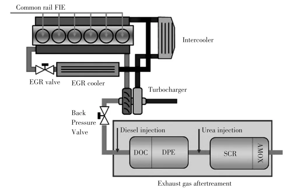
Figure 1.Illustration of modern heavy-duty diesel engine with aftertreatment system
The above discussed measures to improve air quality proved to be effective[2].Currently,attention is shifting towards minimizing global warming and on midterm towards scarcity of fuels.This results in fuel efficiency and tank-to-wheel CO2emission targets;with GHG Phase 2,40%fuel consumption reduction at vehicle level is targeted in 2027 for US trucks compared to 2010.In Europe,CO2reduction levels up to 20%are discussed for 2020.
As illustrated by historic fuel consumption of 40 ton trucks,it has been extremely challenging to simultaneously reduce fuel consumption and pollutant emissions;fuel consumption stabilized around 35 L/100 km,since the introduction of increasingly strict emission limits[3].Despite developments in the field of battery and fuel cell technology,internal combustion engines will remain the main propulsion source in the upcoming decades for heavy-duty applications.This is motivated by its combination of energy density,power output and reliability.In orderto meetupcoming targets,the complexity of diesel engines and powertrains will further grow:introduction of high efficient aftertreatment systems,advanced turbocharging and FIE systems,and energy recovery systems(waste heat recovery,hybrid electric drivetrains)are foreseen.On the long term,application of high efficient advanced combustion concepts and renewable fuels is anticipated.
Besides engine hardware,electronic control systems largely determine the diesel engine characteristics,in terms of performance,emissions and efficiency.Up to now,map-based control strategies have been widely applied.Moreprecisely,forvaryingenginespeed and load conditions,look up tables are implemented,which specify the required control settings.However,development of these map-based control systems is reaching a turning point.With growing engine complexity,powertrain diversity and the need for robust performance under varying on-road conditions,development time and costs reach unacceptable levels.Consequently,model-based control development becomes inevitable[4].By following a model-based approach,we can deal in a systematic and efficient way with different system configurations,with interactions between subsystems, and with varying dynamic operating conditions.This significantly reduces development time and costs and enables realization of minimal fuel consumption(and CO2emissions)for a wide range of real-world operating conditions.
This work starts from a review of model-based SCR control developments. Focus is on heavy- duty applications.We present a model-based development approach for diesel engine and aftertreatment control systems.To demonstrate its potential and benefit,this approach is applied to develop a SCR control strategy.Firstly,the operation principle of SCR-deNOxsystems and its control are discussed.Secondly,the proposed modelbased control approach is introduced and applied for Euro-VI aftertreatment development.For various steps in the development process,results are presented.Compared to earlier work,the main contribution of this work is the outlook on future diesel aftertreatment systems and engineaftertreatment control(see Section 4).An integrated engine-aftertreatment control approach(referred to as Integrated Emission Management) is introduced to guarantee real-world optimal and robust performance in the future.Finally,the main conclusions are summarized.
2 Control of Urea-Based SCR-deNOxSystems
Modern heavy-duty diesel engines are equipped with an exhaust gas aftertreatment system to realize near zero impact tailpipe emissions.As shown in Figure 1,these aftertreatment systems consist of a Diesel Oxidation Catalyst(DOC),Diesel Particulate Filter(DPF),ureabased Selective Catalytic Reduction(SCR)system and an Ammonia Oxidation(AMOX)catalyst.Similar layouts can be found in off-road applications.In this chapter,the operating principle of the SCR-deNOxsystem and the associated control problem are discussed in more detail.
2.1 SCR System Description
Figure 2 shows the layout of a standard urea-based SCR-deNOxsystem.In this system,three subsystems can be distinguished[5]the urea dosage system,catalyst system and control system.The dosage and catalyst subsystems will be discussed in more detail below.The control system is dealt with in a separate control subsection(Section 2.2).
2.1.1 Urea dosage system
To form ammonia(NH3),the required reducing reagent for NOx-reduction in the SCR catalyst,an aqueous urea(H4N2CO)solution(also called Diesel Exhaust Fluid(DEF)or AdBlue©)is injected through a nozzle,such that it is atomized in the exhaust pipe,upstream of the catalyst.After evaporation of the water,ammonia is formed in two steps(see also Figure 3):
Thermal decomposition:

Hydrolysis:

The ammonia(NH3)is the essential reagent for the catalytic process in the SCR system.
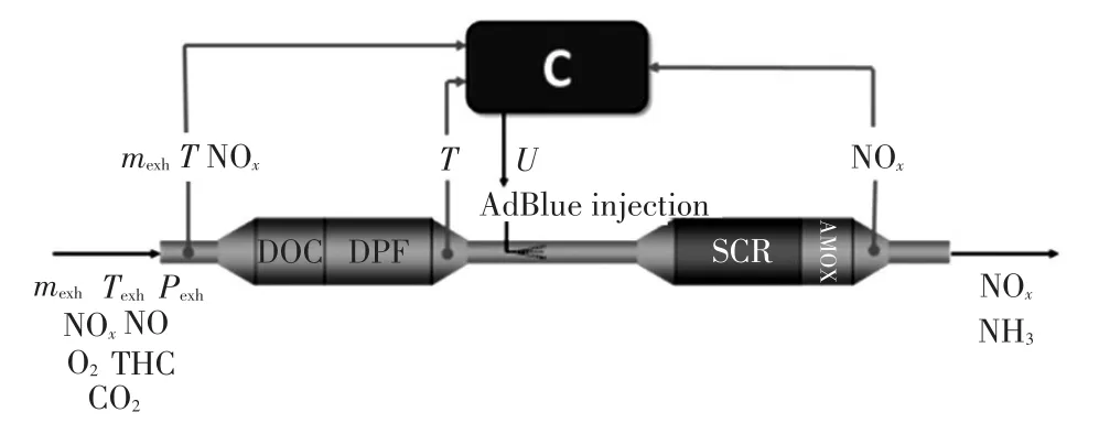
Figure 2.Lay out of urea-based SCR control system[6]
2.1.2 Catalyst system
Inside the SCR catalyst,gaseous ammonia is adsorbed onto the catalyst surface.Using the adsorbed ammonia,the nitrogen oxides emitted by the engine are reduced and converted over the catalyst.This is done according to the following reaction mechanisms:
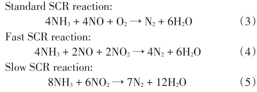
Where the highest NOxconversion reaction rates are found for reaction(4).For high temperatures,maximal achievable NOxconversion is limited by NH3oxidation.
Figure 3 summarizes the main mechanisms inside the SCR system.Only ammonia stored on the catalyst substrate is able to convert NOxinto harmless N2and H2O emissions.In ideal conditions,NOxconversion efficiencies of close to 100%can be achieved.

Figure 3.Phenomenological model of urea-based SCR catalyst system[6]
2.1.3 NOxconversion performance
The NOxconversion performance of an SCR catalyst is a function of:
a.Catalyst temperature;
b. Space velocity,which is reciprocal to residence time and is given by:

Wherėis the volumetric exhaust gas flow rate;ρexhis the exhaust gas density;Vcatis the catalyst volume based on outer dimensions;
c. NO2-to-NOxratio;
d.Ammonia storage level on the catalyst surface.
In order to anticipate the highest NOxconversion reaction rates,it can be concluded from reaction(4)that we target NO2:NOxratios of 0.5.As these values are typically not found in diesel exhaust emissions,a DOC is applied,which oxidizes NO to NO2.Its effect on NO2:NOxratio is illustrated in Figure 4a.Generally,high temperaturesand low space velocitiesincrease NOxconversion efficiency.For a specific NH3slip level of 10 ppm,the stationary SCR conversion efficiency is shown in Figure 4b.
2.1.4 Ammonia surface coverage
Besides the effect of catalyst temperature and space velocity,ammonia surface coverage plays a crucial role to achieve maximum NOxconversion efficiency,as illustrated in the right hand plot of Figure 5.However,the allowable surface coverage level is limited by the risk of ammonia slip,i.e.,excessive NH3emissions out of the SCR catalyst and into the environment.
The distribution and propagation of NH3surface coverage along the length of the SCR,is affected by adsorption,desorption,downstream propagation of gaseous NH3,and consumption of adsorbed NH3by the SCR reactions(3)~(5).As the NH3desorption rate increases with temperature,NH3is propagated downstream more quickly in high temperature operation.The reaction rates of the SCR reaction mechanisms that consume NH3and NOxalso increase with temperature.Because of these effects,the desired NH3surface coverage for an optimal balance between NOxconversion and slip is typically a decreasing function of temperature,see left hand plot in Figure 5.The SCR catalyst has a large ammonia surface coverage,which results in a slow dynamic response.At any given time,the surface coverage is the result of urea and NOxinflow history,over the past thousands of seconds.
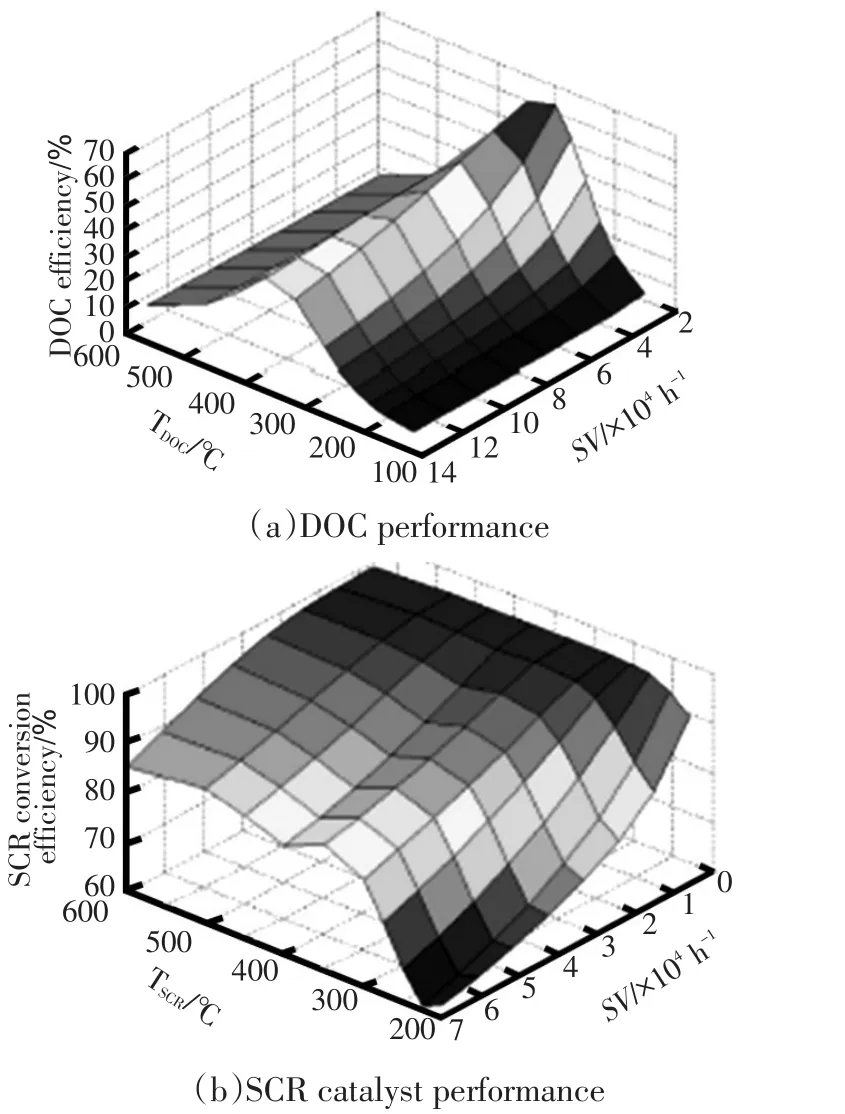
Figure 4.Catalyst performance maps showing catalyst conversion efficiency as function of temperature and Space Velocity(SV)[7]
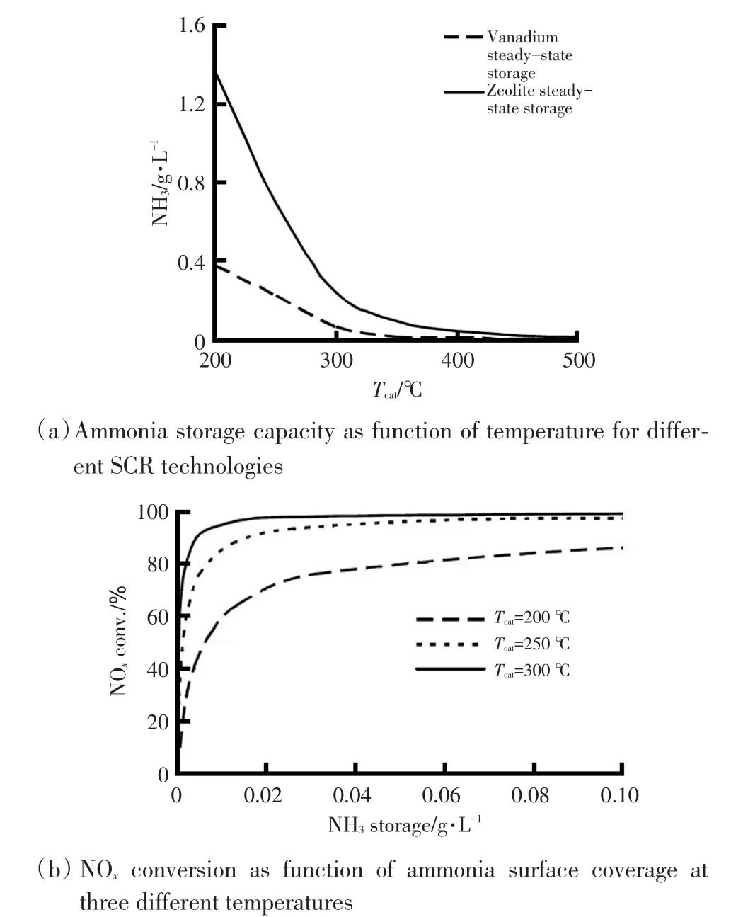
Figure 5.Role of ammonia surface coverage in NOxconversion process[8]
To realize a specific surface coverage level,ammonia can only be actively added,but not removed from the catalyst.This makes sudden rises in exhaustgas temperature and flow rate,resulting for example from a tipin maneuver,especially challenging.Starting from a low temperature situation with a high level of ammonia storage and relatively slow rate of desorption and downstream propagation ofstored ammonia,a sudden rise in temperature and exhaust mass flow significantly speeds up ammonia desorption and downstream propagation.Together with a high initial storage level and large storage capacity,this can result in significant ammonia slip.Although AMOX catalysts are often applied as a safety measure,accurate urea dosing control is essential to avoid unacceptable slip.In the next section,the SCR control problem will be discussed in more detail.
2.2 SCR Control Problem
Figure 2 illustrates the SCR control problem:based on information from mass flow,temperature and emission sensors,the controller C determines the optimal urea dosing.This controller aims to realize desired tailpipe NOxemissions with minimal AdBlue consumption and acceptable NH3slip under varying engine operating conditions.NOxconversion,which is the main performance variable for the SCR system,can be manipulated mainly through the ammonia storage level.This means that the controller has to deal with the slow,non-linear and timevarying SCR system dynamics.Also,the ammonia storage level can only be reduced by cutting off the urea dosing and waiting for the stored ammonia to be consumed through SCR-reactions,also called one-sided control.
2.2.1 Observability
In order to observe the SCR system states,exhaust gas temperature,flow and NOxand NH3sensors are available.However,no practical in-situ measurements are available to determine the actual ammonia surface coverage level.This further complicates the control problem.
In addition,currently available NOxsensor technology is cross sensitive for NH3emissions.The implication on urea dosing control is illustrated in Figure 6;NH3slip is read as NOxemission,so it is not possible to achieve the actual maximal SCR conversion efficiency using closedloop control on the basis of the tailpipe NOxsensor only.To overcome this issue,expensive NH3sensors can be applied,or smart sensing techniques can be used to estimate the levels of tailpipe NOxand ammonia from the NOx-sensor signal only.
The observability problem of the ammonia storage level,the highly non-linear and time-varying SCR dynamics and the extremely wide range of operating conditions and disturbances make this control problem especially challenging.
2.2.2 Real-world performance
Compliance with tailpipe emission limits on the road requires robust,real-world performance under highly varying operating conditions.Engine out exhaust gas conditions vary due to different load cycles,ambient conditions and fuel quality.Besides these disturbances,catalyst washcoat thickness variations and catalyst ageing affect the ammonia storage capacity,and actuators and sensors are prone to production tolerances,ageing and wear.Thisemphasizesthe need forrobustcontrol solutions,which are capable ofmaintaining optimal performance in all real-world conditions.

Figure 6.Illustration of cross-sensitivity of NOxsensors to ammonia,and the implications for dosing control[6]
3 Model-Based Control Development
With growing system complexity,and the need for robust real-world performance,a map-based control approach would result in an unacceptable test and calibration effort to cover all possible operating conditions of interest.To overcome the limitations associated with map-based control,a model-based approach,as illustrated in Figure 7,is inevitable.This enables a systematic,time efficient development process.Models can be applied in the control development process in different ways:
a. Virtual powertrain and simulation environment is built by combining subsystem models.This allows for system optimization by concept,configuration,and component sizing studies.
b. Model-based control design:models are used for system and control design.
c. Model-assisted calibration of control strategies:this includes off-line tuning of the control parameters and performance validation in simulation for various test cases.
d. Real-time models can be embedded in the control system:this supports the development of smart sensors to estimate those variables on-line which cannot be measured directly;and of model-based predictive control strategies.
In this work,the model-based-design methodology is applied forthedevelopmentofaEuroVI/EPA13-compliant SCR urea dosing control system.For different steps in the development process the potential and benefits of this approach are discussed.Additionally,the scalability and flexibility of the modeling environment is used in a configuration and sizing study to assess the feasibility of achieving ultra-low tailpipe emission levels that would be compliant with future legislations.
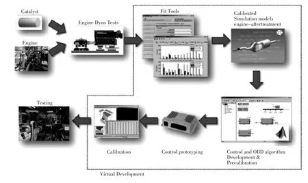
Figure 7.Illustration of model-based control development approach for diesel engine[9]
3.1 Model Development and Validation
The SIMCAT aftertreatment modeling suite is used to set up such a virtual testing platform,called the Virtual Exhaust Line[10]. The models of the individual aftertreatment elements are calibrated and validated using enginetest-cellmeasurements.In Figure8 model validation results are presented, showing accurate prediction of tailpipe NOxand NH3levels.
Models developed on first principles follow the laws of physics.The models used in this work follow the principles of conservation of heat,mass,and momentum.The use of physics-based models results in accuracy over a very wide range of operating conditions beyond the test conditions and therefore,reduces the required measurement effort for the models,while increasing the range of operating conditions where the models are valid.This virtual testing platform allows detailed model- based control development,includingfunctionality and performance testing.
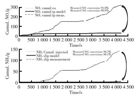
Figure 8.Model validation results:measured vs modeled tailpipe NOxand NH3levels
3.2 Model-Based Control Design
Because of the strong non-linearity of SCR NOxreduction and NH3storage,combined with large variations in operating conditions,the dynamic behavior of the SCR catalystis strongly time-varying and temperature dependent.Additionally,the storage state of the SCR catalyst is not directly measurable.
For optimal NOxconversion with minimum ammonia slip,an ammonia storage control approach has been identified as the most promising approach[11].To apply a storage control strategy,an estimate of the storage level must be available to the control system in real time.An online aftertreatment model,using inputs from available sensor signals,can act as an observer of the catalyst state,providing a real-time estimate of the actual ammonia storage level on the catalyst substrate.This enables the use of a model-based ammonia storage control strategy,which can realize the ammonia storage level that yields the maximum achievable NOxreduction without exceeding slip limits during fast transients.
To achieve an optimal trade-off between the NOxconversion and ammonia slip in dynamic conditions,the ammonia storage controller is optimized for fast response to transients,by adopting a feedforward approach.By using only measurements upstream of the SCR catalyst,the response of the urea dosing controller to changes in exhaust gas conditions is not affected by the long timescale of the SCR storage dynamics,and an immediate response is possible.In Figure 9 the structure of the model-based storage controller is presented.
Many factors affect the NOxconversion performance of the aftertreatment system in real-world conditions.These including tolerances on sensors,the urea dosing system,and the catalysts themselves,and ageing affects.Additionally,OnBoard Diagnostics(OBD)requirements mustbe complied with,byraising warningswhen compliant performance cannot be guaranteed.To comply with these requirements and maintain NOxconversion performance,real-time monitoring and feedback control of the SCR system must be applied.
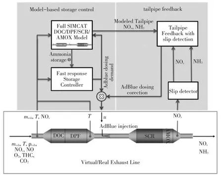
Figure 9 Urea dosing control with ammonia storage control andtailpipe feedback[6]
In this work,the model-based storage controller is combined with a tailpipe feedback module to provide robustness to disturbances.The tailpipe feedback module adjusts the dosing demand from the storage control system on the basis of the actual tailpipe NOxand NH3levels.This aspect of the urea dosing control system acts on longer timescales than the feedforward ammonia storage controller,to allow for the long timescale response of the ammonia storage level to take effect.The tailpipe feedback controller compares the measured and modeled concentrations of tailpipe NOxand NH3,and suppresses the difference by adjusting the dosing demand for the AdBlue injector.The dosing demand signal used for the control model however,is not adjusted by the tailpipe feedback controller.In this way,the modeled tailpipe emissions remain unaffected and serve as setpoints for the tailpipe feedback controller,and thus the real exhaust line.
The use of NOxsensors in the tailpipe of an SCR aftertreatmentsystem is complicated by the cross sensitivity of the NOxsensor to NH3.This problem can be alleviated by the use of a separate NH3sensor.From a cost and complexity perspective however,this is not a favorable solution.Another possibility is to apply an NH3slip detection algorithm to the NOxsensor signal.This is the approach adopted in this work,which is described in more detail in[6].
3.3 Control Validation-Simulation Study
The performance of the urea dosing control strategy is first tested using the Virtual Exhaust Line(VEL).The virtual exhaust line represents a standard Euro-VI aftertreatment system shown in Figure 9.The real-time aftertreatment model used for the model-based storage controller,called the On-line Model(OLM),is identical to the Virtual Emission Line models in functionality and detail,but is fed with a limited number of signals from virtual NOx,temperature and mass-flow sensor-models that are part of the VEL.This results in an accurate representation of the operating conditions of the modelbased urea dosing control strategy,and gives great flexibility in testing different cycles as well as various offnormal conditions.
The aftertreatment catalyst models in this simulation environment are fitted to a state-of-the-art Euro VI heavyduty aftertreatmentsystem.The urea dosing control strategy described in this paper was developed and finetuned in the virtual testing environment,and Euro VI level emission compliance,as well as low slip in demanding user cycles was shown in virtual testing.Table 1 shows the nominalperformanceachieved bythemodel-based ammonia storage controller,compared to a simple NOxfollowing,Ammonia-to-NOx-Ratio(ANR)controller,which injects ammonia proportionally to the engine-out NOxrate.
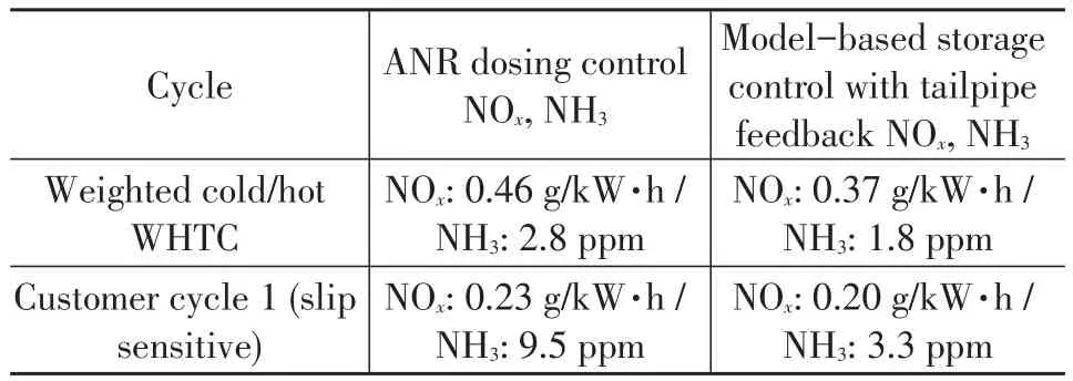
Table 1.Nominal performance of model-based storagecontrol,compared toANR 1.1followingcontrol[6]
The virtual testing environment can also be used to asses aftertreatment performance in non- nominal conditions.Such conditions can include errors in sensors and actuators of the urea dosing control system,extreme ambient conditions,catalyst ageing or washcoat thickness variations,or off-normal engine operation resulting in different exhaust gas conditions.This work focusses on the effect of errors in aftertreatment sensors and actuators.The range of errors treated is presented in Table 2.

Table 2.Overview of disturbances applied to urea dosing control system[6]
These type of disturbances can be suppressed by the tailpipe feedback module of the dosing control strategy.The tailpipe feedback module works by detecting differences in tailpipe NOxand NH3emissions between the OLM and the(virtual)aftertreatment system,and adjusts the dosing correction factor to suppress these differences.When a disturbance is introduced to the system,the response time of the closed loop system is determined by the combination of the SCR and the feedback control dynamic response.In Figure 10 the response of the dosing correction factor to a 10%overdosing bias on the urea injector introduced att=0 s is shown.The dosing correction factor converges to 0.9,and thereby suppresses the introduced error.
In real-life operation,disturbances such as sensor or injector bias are typically constant or very slowly varying.The relatively long time-scale response of the dosing correction factor is therefore sufficient to suppress such disturbances.
As a demanding test for the robustness of the urea dosing control strategy,combinations of the disturbances in Table 2 are applied in the virtual testing environment.A set of 25=32 tests was carried out,where each of the 5 disturbances is either minimum or maximum.These cases all represent extreme outliers in terms of system tolerances;all the considered disturbances are at the limit of their tolerance range,simultaneously.
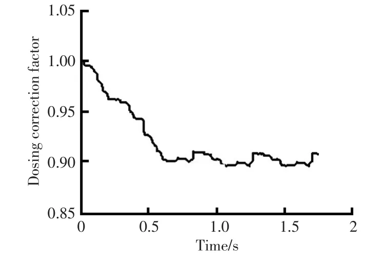
Figure 10.Transient response of dosing correction factor to a disturbance of the urea dosing system
Figure 11 shows the resulting emissions performance for the 32 worst-case disturbance combinations,after convergence of the dosing correction factor.For all tested combinations of disturbances,the urea-dosing control strategy is able to maintain conformity on the tested customer cycle,which represents a high-load cycle susceptible to ammonia slip.This shows the tailpipe feedback solution is capable of suppressing a wide range of disturbances while maintaining robust performance.
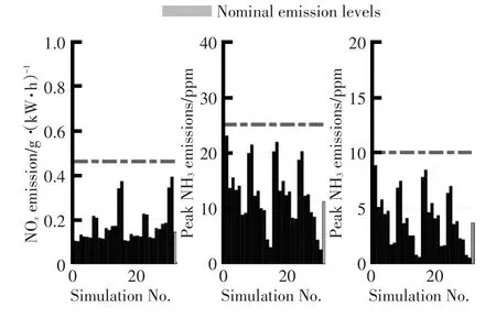
Figure 11.Emission performance under the influence of combined worst-case disturbances[6]
The remaining sensitivity observed for the storage controller with tailpipe feedback results from non-linearity of the aftertreatment system,and in the particular case of the biased NOxsensors,the small sensitivity of the slip-detection to sensors errors.
An important disturbance to the model-based control strategy,which was not treated in the virtual testing results,lies in difference between the On-Line Model and the exhaust aftertreatment system.This effect and other complications in real-life operation are identified through an experimental validation of the urea dosing control strategy on a state-of-the-art Euro VI heavy-duty engine and aftertreatment test-setup.
3.4 Control Validation-EngineDynamometer
The urea dosing control system developed on the virtual testing platform is validated on a real testing platform,consisting of a Euro VI level engine and aftertreatment system in an engine test-cell.For the experiments presented in this work,the urea dosing control system, including the online model, have been implemented on adSpacerapid controlprototyping platform.Due to the realistic nature of the virtual testing environment,the implementation effort to go to a real testing platform is minimal.Additionally,due to the high accuracy ofthe aftertreatmentmodels,the control calibration obtained using the virtual testing environment needs only minor adjustments to work optimally on the physical exhaust aftertreatment system.
For this work control experiments have been carried out for both nominal aftertreatment performance as well as with a disturbance on the engine-out NOxsignal.The model-based urea dosing control system is compared to a production,Euro VI-generation control system in use on commercial vehicles.
In Figure 12 the results of the control experiments are presented.A zero percent error on the engine-out NOxsensor represents nominal conditions.In this condition,the model based urea dosing control strategy matches the NOxconversion and improves on the slip performance of the reference control system.Once the disturbance on the engine-out NOxsensor signal is applied,the reference controller is not able to maintain compliant tailpipe emissions,especially in terms of average and peak tailpipe ammonia slip.The model-based urea dosing control strategy with tailpipe feedback however,shows greatly reduced sensitivity to the disturbance of the engine-out NOxsensor,and is able to maintain compliant emissions in all cases.
The benefit of the model-based design and modelbased control strategy with high fidelity On-line-Model is apparentin itsNOxconversion and ammonia slip performance,as well as in providing a reference for the tailpipe feedback correction that brings robustness to disturbances.Furthermore,the development of the control strategy in the model-based,virtual testing environment has resulted in a high performance,robust control system that can be easily ported to a real testing platform.Only minimal changes to the control calibration were required to reproduce the virtual test results on the real testing platform.
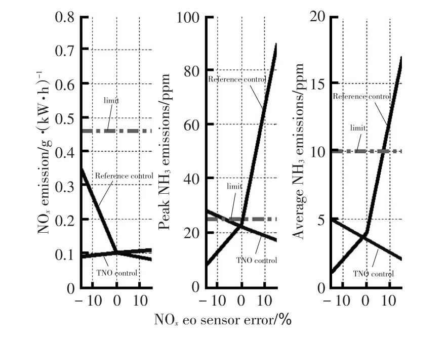
Figure 12.Experimental robustness of dosing controllers to biased engine-out NOxsensor
4 Outlook on Future Diesel Aftertreatment and Control Systems
This chapter will give an outlook on the impact of future legislation on required aftertreatment and control technologies.For automotive industry,the main challenge is to simultaneously meet the increasingly strict emission targets and reduce the CO2emission and fuel consumption.Applying the introduced model- based approach,requirements on aftertreatment systems to meet future emissions standards are explored in a concept study.New technologies such as the Passive NOxAdsorber(PNA)and SCR on Filter(SCRoF)are expected to be used in the future for heavy duty aftertreatment systems.Therefore,aftertreatment configurations including these new technologies are modeled in the virtual exhaust line framework. Additionally, the model- based control approach is further extended by integrating engine and aftertreatment control.
The currentlegislation limits on tailpipe NOxemissions for Europe and the US foron road HD Diesel(HDD)vehicles are 0.46 g/kW·h and 0.2 g/bhp-hr respectively.Additionally,Euro-VI legislation also specifies In Service Conformity regulations(ISC),while the US specifies Not to Exceed(NTE)limits that target emissions in the real world.Asian countries are also quickly following suit in emission standards,including OBD and in-service conformity requirements[12].
Further reductions in legal emissions limits are expected in the near future.The California Air Resources Board(CARB)is leading the introduction of next level emissions standards,where manufacturers may choose to certify their engines to three optional NOxemission standards:0.10,0.05 or 0.02 g/bhp-hr[13].These emissions levels,representing a 90%reduction as compared to current limits,are expected to become the norm in the near future.
Challenges in meeting stringent emission norms arise from the fact that the tailpipe NOxlimits have to be met without a significant penalty on fuel consumption.This limitation can be looked at from two different angles.Firstly,the legislation will also impose penalties on CO2emissions,which means the fuel consumption must be as low as possible.Secondly,from an economical perspective,fuel and Diesel Emissions Fluid (DEF/AdBlue)consumption should be minimized.Additionallegal requirementsareposed in theform ofreal-world robustness requirements.Meeting the emission targets in the presence of real-world disturbances and uncertainties in the system such as ageing,poisoning,drive cycle variations,and system and sensor tolerances represents a major technical challenge.
4.1 Model Library of New Aftertreatment Systems
In the previous chapter the application of modelbased software toolchain towards control systems developmenthasbeen presented.Themodelbased toolchain can also be used to create virtual engine and aftertreatment.The virtual exhaust line toolchain has been explained in detail in[10],wherein components of a standard Euro-VI aftertreatment system were presented.The components presented are the DOC,DPF,SCR,and AMOX.
More recently,technologies such as Passive NOxAdsorber(PNA)and SCRonDPF are also gaining popularity.It is expected that these technologies would be necessary in order to meet the ultra-low NOxemission targets.A brief overview of the new technologies is presented here.
4.1.1 Passive NOxadsorber
The PNA catalyst is a NOxstorage device that is used to mitigate the poor low temperature performance of the SCR catalyst.At low temperatures(below 160℃),the PNA is capable of storing NOxemissions by adsorbing it onto the catalyst surface.Once the exhaust temperature increases,the adsorbed NOxis released,and it can be converted by the SCR system downstream.The low temperature performance of the PNA becomes particularly important considering the fact that the SCR system is capable of conversion efficiencies of over 97%once the engine and aftertreatment system are warmed-up.The emissions in the cold start-up phase can now be significantly lowered using the PNA catalyst.
4.1.2 SCR on DPF
The SCR on DPF(SCRoF),as the name suggests,is capableofsimultaneouslyreducingNOxaswellas Particulate Matter(PM)emissions.It is essentially a DPF with SCR catalytic material coated on its wall filter.The DPF can be replace by the SCRoF,meaning there is a higher volume of NOxconversion catalyst available.This increases the efficiency of the aftertreatment system.Placing the SCRoF closer to the engine also results in achieving quicker light-off temperature,which can help reducing emissions in the warm-up period(during cold start conditions).
In the upcoming section,the importance of having detailed models of the PNA and the SCRoF to meet future emissions target will be shown.Following the model based design approach presented in the previous section,the physics of the PNA and the SCRoF can be modelled.They follow the same structure as the earlier models presented in[9].The development,validation,as wellas ECU embedment of the SCRoF model has been explained in detail in[14].
4.2 Concept Study on Aftertreatment Technologies toMeet theFutureLimits
A feasibility study was conducted to evaluate the technological requirements for the aftertreatment system in order to meet the future demands.Different aftertreatment technologies and configurations were studied.The main motivation behind this work is to identify an aftertreatment system that is capable of meeting ultra-low tailpipe NOxemission levels.A technically feasible solution capable of being deployed in the real world is a base requirement.
Ultra-low NOxlevels that are expected to be applied in the next few years’time can be considered in two steps-1)a 75%reduction from current levels,and 2)followed by a 90%reduction.Note that the 75%and 90%steps are an assumption,and it could very well be that the new limits,especiallyfrom CARB/EPA stipulatea 90%reduction in one step.An engineering safety margin of 15%is applied.Using these numbers,the expected tailpipe NOxemission limits for future legislation can be summarized in Table 3.

Table 3.Table showing current and expected future legislation limits on tailpipe NOxlevels for on road HD Diesel vehicles
Several aftertreatment technologies currently exist in the mainstream market,with new technologies such as SCRoF also gaining popularity.For the work presented here,a baseline aftertreatment technology consisting of DOC,DPF,SCR,and AMOX is considered.The baseline aftertreatment system is calibrated to meet Euro-VI as well as current EPA and CARB standards.New technologies such as the PNA and the SCRoF are also considered.
Validated physics based aftertreatment models and controls presented in the previous section are used in this work to create a virtual exhaust line.Focus here is on obtaining a high efficiency aftertreatment system.So,the engine output is considered to be constant;i.e.,engine measures and interaction with the aftertreatment system is not considered.Engine output data from measurements for WHTC and FTP cycles are used-WHTC for the Europe and FTP for the US.Engine output consists of transient measurements of temperature,flow,pressure and exhaust gas species compositions measured on an Euro-VI capable engine.The summary of the engine output measurements for these two cycles are given in Table 4.
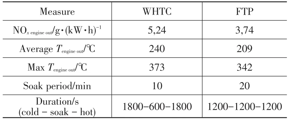
Table 4.Summary of engine output measurement for WHTC and FTPcycles
A cold-soak-hot cycle is considered for both WHTC and the FTP.Two primary methods of further reducing tailpipe NOxemissions are:
a. increasing the efficiency of the aftertreatment system.
b. reducing the engine out NOxemissions.
Efficiency ofthe aftertreatmentsystem can be improved by increasing the temperature of the exhaust gas,while lower engine out emissions can be obtained in the existing configuration by high EGR flows.
In simulating the performance ofthe baseline aftertreatment configuration,it was noticed that in order to meet the ultra-low tailpipe NOxtargets,either the average exhaust gas temperature had to be increased by at least 150℃or the engine out NOxemissions had to be reduced by 80%.Both these numbers,although technically feasible to obtain(through better thermal management,exhaust burner,or high EGR flows),they are not practical enough to be implemented especially considering the limitations on fuel consumption and CO2emissions.It was also noticed that the cold part of the test cycle(i.e.,during the warm-up period)produced the most of the emissions.Once the system had warmed-up,the emissions increased by only 7%for the rest of the cycle.
Important conclusion from the above study indicates that with the current baseline,although the 90%reduction target can be technically met by increasing exhaust gas temperaturesand by reducing the engine outNOxemissions,the increase in fuel consumption does not make this a viable option.This shows that alternative aftertreatment technologies may have to be considered.
As mentioned earlier,alternative aftertreatment technologies such as the PNA,SCRoF,and closed coupled SCR(ccSCR)are also considered in combination with the traditional aftertreatment technologies. The existing components in the aftertreatment line are replaced by similarcomponents(e.g.,PNA,SCRonDPF,ccSCR)wherever possible.For example,DOC can be replaced by a PNA and the DPF and SCR can be replaced by the SCRoF.The total volume of the aftertreatment system is kept the same asthe baseline configuration,while replacing components.This is to make an even comparison and considering minimal impact on packaging design.
With the help of simulations,the most promising of these solutions was found to be a configuration consisting of PNA,SCRoF,SCR,and AMOX.The PNA stores NOxemission during the cold cycle and releases it once the temperatures are above 160~180 ℃,which is the light-off temperature for the SCR.This reduces the NOxemissions in the cold part of the cycle.Additionally,the presence of SCRoF and SCR simultaneously,results in a higher capacity for NOxreduction.The overall result is an increased aftertreatment efficiency with respect to NOxreduction. The baseline and the best feasible configurations are shown in Figure 13.

Figure 13.Different aftertreatment configuration possibilities for a HDD engine.To meet ultra-low NOxemission level,configuration with PNA-SCRonDPF-SCR-AMOX seems to be most promising
The result of the simulation study is shown in Figure 14 for the WHTC.The baseline and the best case aftertreatment system performance are compared for this cycle.Any point lying within the yellow and green shaded regions mean that they are within the legislative limits for 75%and 90%reduction targets,respectively.
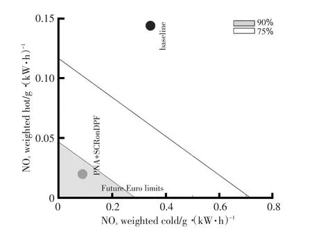
Figure 14.Performance of baseline and best case aftertreatment system with respect to future emission targets
In summary,the following conclusions can be drawn from this study:
a. The configuration with PNA and SCRonDPF replacing the DOC and DPF shows the most promising results;
b. The 90%target for WHTC using PNA and SCRonDPF is just met.The cold-start of WHTC is still a limiting factor to achieve even lower emission levels;
c. For the FTP cycle,the average temperature over the cycle is lower than the WHTC.This makes it difficult to meet the 90%reduction on this cycle.
The aftertreatment technologies and aftertreatment control systems in the market currently are marginally able to meet the emission demands of the future European and US emissions targets.To achieve robust compliance with future emission standards,there is a necessity for the engine and the aftertreatment system to be working together.
4.3 Model-Based Control of Engine and Aftertreat-Ment System
Currently,engine and aftertreatment system functions are mostly independent of each other.Where there is interaction,it is in the form of a mode switching control,which is done in order to heat up the aftertreatment system quickly by raising the engine out temperatures.Interaction between engine and aftertreatment systems in the form of integrated controls are necessary to not only optimize the fuel consumption,but also to meet future emission targets.This section presents a framework for a model-based integrated emissions management controller. While rudimentary levels of integration between engine and aftertreatment systems already exist in the market,these are mostly rule-based,mode switching type of controls.Their main function is to alter the engine operating conditions,such as EGR ratio or diesel injection timing,to aid in quick heat up of the aftertreatment system,and they are not optimized for fuel and AdBlue consumption simultaneously.Furthermore,these controllers switch between look up tables and their calibration is typically done on a type approval drive cycle.This makes their calibration elaborate to meet robust performance.
4.3.1 Integrated emission management controller
The Integrated Emission Management (IEM)controller uses a model-based optimal control approach to continuously seek acostoptimalfueland AdBlue consumption point for the powertrain performance under real-world operating conditions[15].Furthermore,this strategy allows for real time monitoring of emissions-a condition that is also likely to be introduced under the new ultra-low NOxemission legislation.It uses a model-based optimal control approach to continuously select optimal set-points to the engine,based on the state of the engine and the aftertreatment system.Figure 15 shows the structure of the IEM approach towards minimizing fuel and AdBlue costs.Engine and aftertreatment models(different from the SCR control model)are embedded in the IEM controller.This controller acts on top of the existing engine and urea dosing controller.In this way,the pre-existing engine controllers can still be used.However,instead of receiving set-points from pre-calibrated look-up tables,the engine controller receives optimal set points from the IEM controller in real time.
4.3.2 Supervisory control
The IEM is a supervisory controller that coordinates the functioning of the low level air path,fuel path,and urea dosing controllers.The main aim of the IEM controller is to minimize a cost function,which is defined as the total running costs at each time instance of the drive cycle;i.e.,to minimize the fuel cost and the Adblue(Diesel Emission Fluid)cost at every time instance.Fuel flow rate is calculated by running a steady state version of the mean value engine model.A steady state engine model is preferred for reduced computational efforton the controller.This is a valid assumption because the engine dynamics are much faster compared to the thermal dynamics of the aftertreatment system.The aftertreatment model is a combination of its thermal dynamics and a static NOxconversion model based on temperature and space velocity.The AdBlue consumption is calculated assuming stoichiometry between urea and NOxconversion and an aftertreatment efficiency.The aftertreatment efficiency is obtained from the SCR model presented above and predicting the NH3storage on the catalyst.The IEM uses optimal control theory to minimize the cost function.Details about obtaining the optimal solution,the robustness of the solution and its sensitivity to disturbances are explained in[7],and[15]~[18].
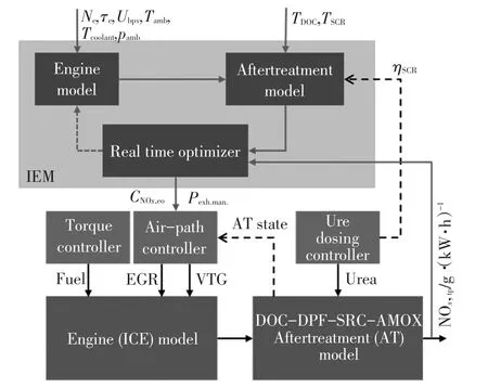
Figure 15.Structure of the integrated emissions management control strategy and its relation with the low level engine and aftertreatment controllers
Figure 16 explains the concept of the IEM controller that is essentially exploiting the concept of EGR-SCR balancing.The CO2-NOxtrade-off curve is a well-known concept for diesel engines.This means that we aim for lowest BSFC(lower CO2),which typically corresponds to high engine out NOxemissions.This requires an increased SCR efficiency to reduce the excess emissions to below the tailpipe targets.
Map-based control strategies have to apply safety margins in their engine out NOxlevels in order to meet the tailpipe limits.This is done to deal with varying operating conditions,ageing and the effect of system tolerances.This leads to lower tailpipe calibration than necessary and to lower engine out calibration.As a consequence,fuel consumption from the engine and CO2emissions are higher.
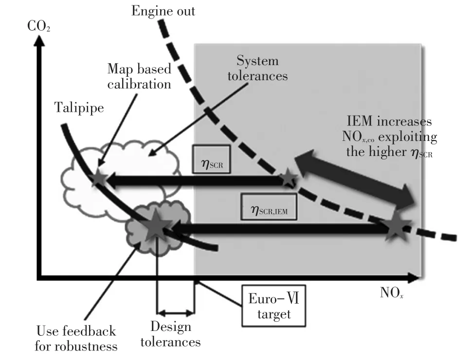
Figure 16.EGR-SCR balancing principle of IEM controller
4.3.3 EGR-SCR balancing
The concept of EGR-SCR balancing relies on obtaining the optimal overall system performance by finding the maximum SCR performance.EGR flow is altered correspondingly such that engine out NOxmatches SCR conversion efficiency,such that low tailpipe emissions are obtained.The engine operating point is then closest to the minimal BSFC/CO2point.In the case of the IEM,the aim is to operate the SCR system at highest efficiency by increasing the average operating temperature.This allows for increasing the engine out NOxemissions and exploiting the higher SCR efficiency to meet legislative emission targets.In addition,the effect of system tolerance can be minimized by adding a tailpipe feedback to the optimal control framework[17].
Model-based control strategies like the urea dosing controller or the IEM controller can be applied to lower fuel consumption and guarantee to robustly meet tailpipe emission norms on real world drive cycles.In addition to this they can also play an important role in OBD requirements.For example,due to the robustness of the models towards NOxemissions,early lighting up of the Malfunction Indicator Lamp(MIL)can be avoided.Modelbased controllers also offer the capabilities of real time monitoring of emissions.
4.4.4 Mixed testing
Besides application in control strategies,real-time models attract more and more attention for combination of virtual and real testing,so-called mixed testing.This trend is not only seen in development and testing,but also in legislation.The growing complexity of the powertrain system offers additional challenges in the development and calibration of the powertrain.Models can also be used in the developmentphase forcalibration,testing,and validation of new powertrain components and control strategies.This way the number of hours spent on the testbed for these components can be reduced.Virtual models can also be used in conjunction with real hardware,e.g.Hardware-in-the-loop,engine-in-the-loop.For example,the engine hardware can be tested in real time along with a calibrated virtual exhaust line in a climate chamber to study the effect of changing climatic conditions on the engine and aftertreatment performance.Such a concept avoids the necessity for an expensive aftertreatment system and associated measurement equipment,offering a unique and cost efficient way for future developments.This concept of mixed testing is explained in[4].
5 Conclusions
In this work,a model-based design and control development approach is presented.This approach is applied to develop engine and aftertreatment control systems,and to explore aftertreatment configurations to meet future emission standards.In summary,the following conclusions are drawn from this study:
a. The importance of powertrain control will further grow and control development will face a turning-point in the near future.Due to robust performance requirements and growing system complexity,development time and costs will reach unacceptable levels using current mapbased methodologies.Model-based control development will become the industry standard;
b. Model-based SCR control is key to meet future emission targets.To reduce safety margins and realize maximal NOxconversion with acceptable NH3slip under varying operatingconditions,model-based ammonia storage control is crucial.By adding NOxsensor-based tailpipe feedback,the robustness of the SCR control system is significantly improved;
c. Future emission targets require new aftertreatment technologies and integrated engine-aftertreatment control.It is shown that an aftertreatment concept with Passive NOxAdsorber and SCRonDPF is most promising.To meet ultra-low tailpipe emissions,it is increasingly importantto maximize overallengine-aftertreatment performance.This gives the required optimal and robust performance.The introduced Integrated Emission Management concept shows promising results.
1 I.E.Agency.Technology roadmap-biofuels for transport,2011.https://www.iea.org/publications/freepublications/.
2 Vermeulen R,Vonk W,van Gijlswijk R,et al.The Netherlands In-Service emissions testing programme for heavy-duty vehicles 2015-2016-annual report.TNO 2016 R11270,TNO,2016.
3 Eurotransport.LKW Verbrauchswerte von 1966 bis 2014:Immerabwärts,2014.http://www.eurotransport.de/news/lkw-verbrauchswerte-von-1966-bis-2014-immerabwaerts-6550678.html.
4 Willems F.Inaugural lecture:The self learning powertrain-Towards smart and green transport,2017.https://pure.tue.nl/ws/files/59039327/Willems_2017.pdf.
5 Willems F,Cloudt R.Experimental demonstration of a new model-based SCR control strategy for cleaner heavy-duty diesel engines,IEEE transactions on Control Systems Technology,2011,19(5):1305~1313.
6 Hommen G,Kupper F,Seykens X,Robust,Model-Based Urea Dosing Control for SCR Aftertreatment,SAE Technical Paper 2017-01-0938,2017.
7 Willems F,Mentink P,Kupper F,et al.Integrated emission management for cost optimal EGR-SCR balancing in diesel engines.7th IFAC Symposium on Advances in Automotive Control,Tokyo,2013.
8 van den Eijnden E,Cloudt R,Willems F,et al.Automated model fit tool for SCR control and OBD development,SAE Technical Paper 2009-01-1285,2009.
9 Mentink P,Willems F,Kupper F,et al.Experimental Demonstration of a Model-Based Control Design and Calibration Method for Cost Optimal Euro-VI Engine-Aftertreatment Operation,SAE Technical Paper 2013-01-1061,2013.
10 Cloudt R,Saenen J,van den Eijnden E,et al.Virtual Exhaust Line for Model-based Diesel Aftertreatment Development,SAE Technical Paper,2010-01-0888,2010.
11 Skaf Z,The state of the art in selective catalytic reduction control.SAE World Congress and Exhibition,Detroit,2014.
12 Delphi.Worldwide Emission Standards Heavy Duty and Off-Highway Vehicles.2016/2017.https://www.delphi.com/about/emissions_standards.
13 Dieselnet,Emission Standards:USA Heady Duty Onroad Engines,https://www.dieselnet.com/standards/us/hd.php.
14 Ramesh S,van den Nieuwenhof R,Seykens X,et al.Development,Validation and ECM Embedment of a Physics-Based SCR on Filter Model.SAE Technical Paper 2016-01-8075,2016.
15 Cloudt R,Willems F,Integrated Emission Management strategy for cost-optimal engine and aftertreatment operation.SAE International Journal of Engines,2011,4(1):1784~1797.
16 Mentink P,van den Nieuwenhof R,Kupper F,et al.Robust emission management strategy to meet real-world emission requirements for HD diesel engines.SAE International of Engines,2015,8(3):1168~1180.
17 Ramachandran S,Hommen G,Mentink P,et al.Robust,Cost-Optimal and Compliant Engine and Aftertreatment Operation using Air-path Control and Tailpipe Emission Feedback.SAE International Journal of Engines,2016,9(3):1662~1673.
18 Willems F,Kupper F,Rascanu F,et al.Integrated energy and emission management for diesel engines with waste heat recovery using dynamic models.Oil and Gas Science Technology,2015,70(1):143~158.
(Editor Hu Pan)
Writingmark:A ArticleID:1000-3703(2017)09-0007-13
date:2017-07-18.
