Analysis of reaction torque-based control of a redundant free-floating space robot
2017-11-17MingheJINChengZHOUYechaoLIUHongLIU
Minghe JIN,Cheng ZHOU,Yechao LIU,Hong LIU
State Key Laboratory of Robotics and System,Harbin Institute of Technology,Harbin 150001,China
Analysis of reaction torque-based control of a redundant free-floating space robot
Minghe JIN,Cheng ZHOU*,Yechao LIU,Hong LIU
State Key Laboratory of Robotics and System,Harbin Institute of Technology,Harbin 150001,China
Owing to the dynamics coupling between a free-floating base and a manipulator,the non-stationary base of a space robot will face the issue of base disturbance due to a manipulator’s motion.The reaction torque acted on the satellite base’s centroid is an important index to measure the satellite base’s disturbance.In this paper,a comprehensive analysis of the reaction torque is made,and a novel way to derive the analytical form of the reaction torque is proposed.In addition,the reaction torque null-space is derived,in which the manipulator’s joint motion is dynamically decoupled from the motion of the satellite base,and its novel expression demonstrates the equivalence between the reaction torque null-space and the reaction null-space.Furthermore,the reaction torque acted as an optimization index can be utilized to achieve satellite base disturbance minimization in the generalized Jacobian-based end-effector Cartesian path tracking task.Besides,supposing that the redundant degrees of freedom are abundant to achieve reaction torque-based active control,the reaction torque can be used to realize satellite base attitude control,that is,base attitude adjustment or maintenance.Moreover,because reaction torque-based control is a second-order control scheme,joint torque minimization can be regarded as the optimization task in reaction torque-based active or in-active control.A real-time simulation system of a 7-DOF space robot under Linux/RTAI is developed to verify and test the feasibility and reliability of the proposed ideas.Our extensive empirical results demonstrate that the corresponding analysis about the reaction torque is correct and the proposed methods arefeasible.
1.Introduction
A space robot is an important tool for space activities like target capturing,on-orbit servicing,outer space exploration,and so on.It seems to be an extension of human beings’arms,that is to say,our limitations on the field of activities are expanded by the advent of a space robot.Hence,the last 30 years have witnessed an increasing interest towards robotic applications in space.1–5
Unlike a terrestrial manipulator,a space robot is always freefrom the influence of an external force.The coupling relationship between a satellite base and a mounted manipulator will alter the satellite’s position and posture resulting in difficulty in the design of a space robot’s control systems.Besides,the conventional treatment on this coupling of a free-floating space robot is always from the view of one-order differential equations:the rotational momentum conservation equation and the translational momentum conservation equation.6–8The former is just an integrable expression which can be transformed into a position relationship of each link of a space robot,and hence the conclusion of a free-floating space robot’s invariant centroid is derived.Whereas,the latter translational momentum conservation is just a non-integrable relationship and it is also the non-holonomic constraint of a free-floating space robot. Meanwhile, in practical applications, a satellite’s attitude overwhelms its position,as the attitude is so important when considering solar supplement and information communication.9
Furthermore,the way to deal with the satellite attitude is always a hot spot in the field of planning and control of a space robot,and to some degree,the satellite attitude adjustment or maintenance will determine the task implementation.10,11Therefore,path planning algorithms and motion control laws are always the footstones of autonomous control of a space robot.In literature,Dubowsky and Torres planned the trajectory of a space manipulator using an enhanced disturbance map(EDM)to minimize the base attitude disturbance.12They took a 2-DOF manipulator for example;however,it is difficult to obtain the EDMs of manipulators with more DOFs.Vafa and Dubowsky used a virtual manipulator model to develop path planning that reduced the base disturbance,which is called the self-correcting path planning algorithm.13In this method,a system is considered as a linear system with the assumption that the movement of joints is small enough.Nakamura and Mukherjee utilized Lyapunov function to achieve the regulations of both the satellite orientation and the manipulator joint angle simultaneously.14However,the stability of this method was mot demonstrated strictly and the planned joint angles were not smooth.Fernands et al.proposed near-optimalnon-holonomic motion planning to achieve attitude control inspired by the fact that a falling cat can change its orientation in midair.15Nenchev et al.originally utilized the notation of reaction null-space(RNS)to achieve attitude control.16,17To sum up,the RNS method is the only method that can achieve both the base attitude regulation and end-effector trajectory planning simultaneously,and it has been verified in the flight experiments of ETS-VII.
The above proposed algorithms are offline or online motion control of a space robot on the basis of one-order differential motion equations.As for a space robot’s autonomous control,online coordination of the motion between a satellite and a manipulator is crucial.In spite of the fact that the online application of the RNS can be achieved,the end-effector Cartesian path tracking task is limited to position or posture control.The application of the method is quiet a conservative way,and the extended ETS-VII mission is just the path tracking of predefined reactionless paths.In addition,in Cocuzza’s studies,18–20the importance of a reaction torque has been emphasized and the corresponding three algorithms have been proposed,that is,least-squares based reaction torque control,null-space based reaction torque control,and weighted pseudoinverse based reaction torque control aimed at achieving a minimum satellite base attitude disturbance.However,the reaction torque in his studies is the torque acted on the hinge point of the first joint and the satellite base,besides the reaction torque is viewed as the optimization task in his proposed algorithms,and the subsequent experiments are made on a ground-based 3-DOF manipulator on an air-bearing table.
In addition,the dynamic coupling and mounted manipulator reaction control issues are of vital importance in path planning and autonomous control of a free-floating space robot.
The main contribution of this paper is to give a comprehensive analysis of the reaction torque acted on a satellite base’s centroid.Firstly,a novel solution to get the analytical expression about the satellite base reaction torque of a free-floating space robot is proposed.Then,when an abundant DOF exists,the reaction torque can be utilized to achieve satellite attitude adjustment or maintenance,that is to say,the reaction torque is acted as a control task to achieve satellite base active control.Besides,when more DOFs are occupied,the reaction torque is viewed as an optimization task to achieve a satellite attitude disturbance minimization task.Moreover,due to the usage of second-order motion equations,the joint driving torque can be included in the optimization task.
The paper is organized as follows.In Section 2,a kinematics and dynamics model is built,and the inverse kinematics of a space robot is also explained.Then a novel approach to obtain the analytical expression of the reaction torque is developed in Section 3.Section 4 illustrates the reaction torque based inactive control for satellite attitude disturbance minimization.Section 5 shows the reaction torque based active control for satellite attitude adjustment/maintenance with joint torque optimization.In Section 6,a real-time simulator under Linux/RTAI is built and a set of experiments is made to verify the proposed algorithms.The conclusions are summarized in Section 7.
2.Motion equation of a redundant space robot
2.1.Dynamic and kinematic model of a space robot
Considering the linear and angular velocities of the baseis the base linear velocity and wbis the base angular velocity)and the angular velocity of each joint˙θ∈Rn×1,the equation of motion of the space manipulator system is presented as6

where Hb∈ R6×6is the inertia matrix of the base,Hbm∈ R6×nis the coupled inertia matrix,Hm∈ Rn×nis the inertia matrix of the manipulator,cb∈R6is the velocity-dependent non-linear term of the base,cm∈Rnis the velocity-dependent nonlinear term of the manipulator,and τ∈ Rnis the manipulator joint torque.
The motion of the free-floating space robot observes the law of momentum conservation,that is,


where miis the mass of body i,riis the vector from the inertia coordinate system to the centre of the mass,Iiis the inertia matrix of body i,and wiis the angular velocity of rigid body i.

From the rotational momentum conservation equation,the following expression can be obtained:

where IS∈ Rl×lis the rotation related inertia matrix of the base.IM∈ Rl×nis the coupling inertia related matrix of the manipulator,in which l=3 stands for the angular momentum solution.L0is the initial momentum.
Furthermore,assuming that the dimension of the Cartesian space task is m,we can get the following equation from the translational momentum conservation equation:

From Eq.(5),we have

Substituting Eq.(7)in Eq.(6)obtains
2.2.Inverse kinematics of a redundant space robot
Assuming that the initial of a space robot is still,L0=0 and ˙x0=0 are obtained.On the basis of Eq.(8),the generalized Jacobian based inverse kinematics of a space robot is as follows:13

where˙ξ is a null-space arbitrary vector.The corresponding second-order form of Eq.(9)is as follows:

The above Eqs.(9)and(10)are the first-and second-order control laws to achieve generalized Jacobian based endeffector Cartesian path tracking control of a space robot.
Moreover,from Eqs.(5)and(8),we can get the following equations respectively:


Combining Eqs.(11)and(12),we can get

where JEis the extended Jacobian.
Eq.(13)gives a forward kinematic of a space robot,and its general solution is given as

which we call the extended Jacobian(EJ)algorithm.
Furthermore,the acceleration level control law is as follows:

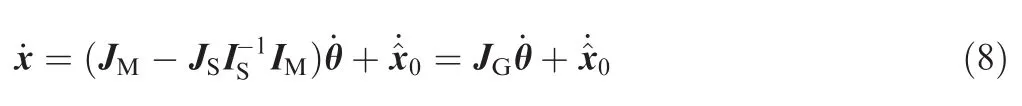
which is the general solution of Eq.(13).Meanwhile,the second-order forward kinematics is obtained as
The above Eq.(16)is an important conclusion for the following derivation in Section 5.
The inverse kinematic based motion control of a space robot can solve satellite base attitude control,zero reaction maneuver,or generalized Jacobian based end-effector Cartesian task control.Besides,the redundant DOF available beyond thatisrequired forthe end-effector Cartesian path tracking is characterized by the null-space of the main task related Jacobian,which can be utilized to assist in the realization of minimizing a position-dependent scalar performance criterion H(θ).Thus the corresponding nullspace vector minimizes˙ξ=k∂H(θ)/∂θ.Furthermore,the joint limits avoidance and the singularity avoidance index are as follows:21
joint limits avoidance:

singularity avoidance:


3.Reaction torque of a free-floating space robot
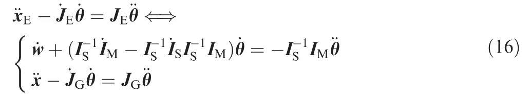
The reaction and joint driving torques are the dynamics quantity of a space robot,and the reaction torque will cause a satellite base disturbance,while the joint torque drives a joint to arrive at the desired position.These torques are shown in Fig.1.
Fig.1 Schematic diagram of the reaction and joint driving torques of a space robot.
The satellite base disturbance is directly caused by the reaction force/torque acted on the satellite base’s centroid.The satellite position is changed by the reaction force,while the satellite attitude is altered by the reaction torque.Because the satellite base rotation is a significant issue which leads to communication problems with a ground control centre,the reaction torque is considered prior.The reaction torque can be calculated by the Newton–Euler iterative algorithm.Thus the analytical form of the reaction torque can be derived,but the corresponding derivation will be too sophisticated.The numerical calculation of the reaction torque is very important in the building of the ground verification systems of a space robot,while its analytical form is of vital importance in the development of a space robot’s control algorithm.
Consider the motion equation of the free-floating base

By recalling the rotational momentum conservation,from the differential expression of Eq.(5),we can obtain


and
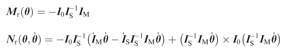
From Eq.(21),we can see that the reaction torque acted on the base’s mass centre consists of Mr(θwith respect toand Nr(θ)with respect toθ.
It is obvious that the above two ways to calculate the reaction torque are equivalent.Besides,the latter is simpler and easier,and this analytical form is obtained by recalling the momentum conservation equation.The derivation Eqs.(19)–(21)also give the relationship between the reaction torque and the rotational momentum conservation of a space robot.
By recalling the reaction null-space of a free-floating space robot,the rotational momentum conservation equation with a zero attitude disturbance

yields the following null-space solution:

In the above Eq.(22),the coupling inertia matrix from the rotational momentum conservation equation comprises a nontrivial kernel,and a set of reactionless joint velocities is as follows:

As for˙θ∈NRNS,the manipulator joint motion is decoupled from the motion of the satellite base.This reactionless kernel is well known as the RNS.
Besides,the reactionless control of a space robot can be achieved by the bounded reaction torque,T0=0.Then we can obtain

which yields the following null-space solution:

Then,a set of reactionless joint accelerations is as follows:

This reactionless kernel is well known as the reaction torque null-space(RTNS),in which the manipulator joint motion is dynamically decoupled from the motion of the satellite base.
Furthermore,the reaction torque can be utilized to achieve satellite attitude control when abundant redundancy exists,besides,joint torque optimization can be achieved in this acceleration level control algorithm.If the end-effector task occupies major DOFs,satellite attitude adjustment/maintenance cannot be achieved,and we aim to obtain satellite disturbance minimization control in this case.
4.Reaction torque based inactive control for satellite attitude disturbance minimization
4.1.Null-space based solution for satellite base disturbance minimization
When the end-effector needs to be sent into the desired position and posture for target capturing,that is to say,major DOFs are occupied to enforce the Cartesian main task,the re will be no abundant DOF to achieve reaction torque based active control.As for the limited redundant DOF,the dynamics task like reaction torque based active control cannot be realized,so the reaction torque based optimization control is adopted in this part to realize satellite minimum disturbance.The redundancy resolution through reaction torque plus driving torque optimization can be concluded into the following quadratic programming(QP)problem:

where w is the joint torque related weight in the multidynamics-task optimization.
The cost function is equivalent to the following leastsquares problem that minimizes


Furthermore,the solution of the above equation can be obtained according to the least-squares solution as

Thus,the solution of Eq.(28)can be derived by substituting Eq.(30)into Eq.(10)as

The secondary optimization task is the least-squares problem for reaction torque plus joint driving torque minimization.Assuming that the redundant DOF is limited,the optimization of the joint driving torque works a little in the null-space of a main task.In other words,the optimization effect is up to the dimension of the null-space of a main task.
4.2.Lagrange multipliers based solution for satellite base disturbance minimization
Another way to solve the multi-torque optimization under an equality constraint is from the view of Lagrange multipliers.With the utilization of Lagrange multipliers λ,the augmented cost function can be expressed as follows:

Substituting the lower part of Eq.(27)into the above equation obtains

The solution is obtained by vanishing the partial derivatives of L(¨θ,λ)with respect to ¨θ and λ as

where B=MTM ∈ Rn×n.The above Eq.(34)is the Karush-Kuhn-Tucker(KKT)condition of the convex optimization problem Eq.(27),and from ∂L/∂¨θ to obtain

Then,substituting Eq.(35)into the expression of ∂L/∂λ obtains

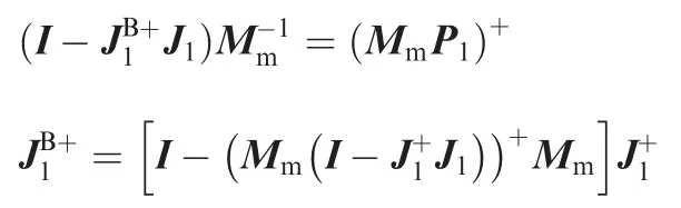
Furthermore,the Lagrange multiplier based solution of Eq.(27)with the combination of Eqs.(35)and(36)is


where is the right pseudoinverse solution of M,andis the weighted pseudoinverse of JG.
4.3.Equivalence between the proposed solutions
The above two solutions of the same constrained least squares problem are equivalent,and the necessary and sufficient condition of the equivalence verification is as follows:

Proof.In order to simplify the derivation,let the matrixand the matrixHence,the proof of Eq.(38)is transformed into the verification that X is the pseudoinverse of A.For the matrix A,the pseudoinverse A+is defined by the following four properties:

Evaluation of the expression AXA results in

Evaluation of the expression XAX results in
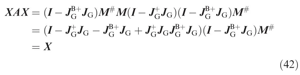
Evaluation of the expression (AX)Tresults in

Evaluation of the expression (XA)Tresults in


Thus,Eq.(39)is proven.However,if w=0 and M ∈ R3×n,the n M#M= (MTM)-1MTM≠0 and B is not a positive definite,that is to say,the se two ways exist a little miss-distance in this case.□
In addition,the above proof shows that different ways to achieve the minimization of the same criterion with the same constraints yields the same results.However,the algorithmic singularity exists in the null-space based solution,which will lead to instability in the real applications of the algorithm,and we will give an intuitional explanation in Section 6.
5.Reaction torque based active control for satellite attitude adjustment/maintenance
5.1.Reaction torque based active control for satellite attitude adjustment/maintenance
Generally speaking,the reaction torque is the origin that brings about satellite disturbance,but in this part,the reaction torque will be viewed as an input variable in the control systems of a space robot,and the planned desired reaction torque can realize satellite attitude regulation.A combination of Eq.(16)and the acceleration form of Eq.(6)will lead to a linear system,which is formulated by the joint acceleration dependent expression as

where wdand wrare the desired and real angular velocities of a satellite base,respectively.In the above equation,the desired reaction torque is up to the desired base angular velocity.
The general solution of the above reaction torque control and end-effector position control is as follows:

The difference between Eqs.(15)and(47)is the special solution,while the general solutions belong to the same set of solutions. To a non-redundant manipulator,that is to say,the same set of solutions are specified vectors,and thus the se two are equivalent.Furthermore,the desired reaction torque set to be 0 will guarantee reactionless manipulation as

5.2.Reaction torque based active control with joint torque optimization
The second-order reaction torque based control can include an optimization task about dynamics quantity.The local joint torque optimization problem can be expressed as

There are two ways to solve the above equation.Thefirst way is a null-space based solution,and the cost function is equivalent to the following least-squares problem that minimizes

Substituting Eq.(47)in Eq.(50),we have

Furthermore,the solution of the above equation can be obtained according to the least-squares solution as

Thus,the solution of Eq.(49)can be derived by substituting Eq.(52)into Eq.(47)as

The above derivation is the null-space based method,and the null-space vector is obtained to achieve the joint torque optimization task.
Another way to solve the joint torque optimization under an equality constraint is from the view of Lagrange multipliers.With the utilization of Lagrange multipliers,the augmented cost function can be expressed as follows:

The solution is obtained by vanishing the partial derivatives of)with respect toand λ as


In order to verify the equivalence between Eqs.(53)and(56),it is sufficient that the following equations exist:
The proof of the se equations is analogy to the derivation from Eq.(38)to Eq.(45).
The above ways are the two solutions to solve the leastsquares problem with an equality constraint(LSE).Furthermore,a convenient space robot behavior can be obtained when minimizing the joint torque in terms of a norm weighted by the squared inverse of the inertia matrix as

Meanwhile,the other torque–level control method for a redundant robot is the dynamically consistent redundancy resolution method to solve the following LSE problem:where τ+and τ-are the upper and lower joint torque bounds,respectively.The Lagrange multipliers based method can give a solution of Eq.(57)and Eq.(58).


Fig.2 Body fixed frame of a 7-DOF space robot.
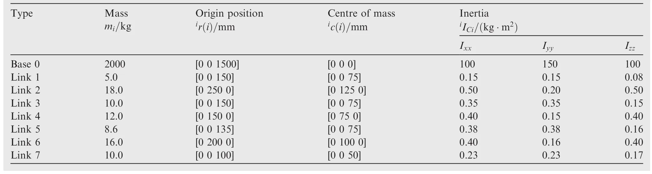
Table 1 Mass properties of the space manipulator.
In addition,the reaction torque based active control can achieve satellite base attitude adjustment or maintenance,and the dynamics criteria optimization can be introduced.
6.Algorithm verification in a real-time simulation system
6.1.Control systems of a redundant space robot
In order to verify the proposed algorithms,we take a seven-DOF space robot for example.The body fixed frame of the space robot is shown in Fig.2,and the kinematics and dynamics parameters are listed in Table 1.
To a space robot,ground hardware-based verification methods such as air-bearing table,22airplaneflying or freefalling motion,23and suspension system are costly built.24Recently,a kind of hybrid simulation method following the principles of dynamics simulation and kinematics equivalence has been presented,which is called hardware-in-the -loop simulation systems.25In this part,we build a real-time simulation system of a redundant space robot under Linux/RTAI to explore the capabilities and limitations of the proposed method.This real-time numerical simulator is conceived and realized as an aid to the design of the controller of a new space robot in development.
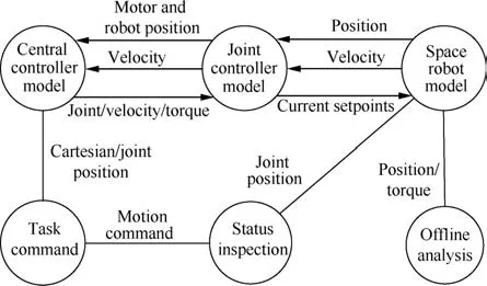
Fig.3 Functional architecture of the real time simulator.
The real-time verification system runs under the Linux operating system with the real time application interface(RTAI)extension,which is a hard real-time extension of Linux.It provides task scheduling and synchronization and inter-task communication services among others.Thefunctional architecture of the simulator is shown in Fig.3.The real-time simulation system consists of 4 modules:
(1)Forward dynamics simulator of the space robot
The dynamic model of the space robot is built of fline in the Sim Mechanics,and the MATLAB Real-Time Workshop is utilized to port the virtual prototype model into c codes for online simulation.
(2)Simulator of the controller
The controller of the real space robot system consists of a central controller and a joint controller.The central controller is responsible for online visual based autonomous planning,Cartesian path planning,joint space path planning,computed torque control,and so on.The functional diagram of the central controller simulator is shown in Fig.4.Whereas,the simulator of the joint controller is used to simulate the servo system of the space robot,and its functional diagram is shown in Fig.5.
(3)Task scheduling and synchronization
The modules mentioned above are made into three realtime tasks and run in three independent threads.Another thread for scheduling the three tasks which is called clock task is created to make the m run periodically,and the synchronous execution of the tasks is achieved by a blocking inter-process/thread communication semaphore.When one executes its period and writes data into the shared memory,the semaphore value is set to one and the next is allowed to run.The shared memory works as a virtual bus.
(4)Monitor
The monitor part runs in another Windows PC installed with Labview which can modify control parameters online and save data to of fline analyze fur the r.It is connected with the main simulator by TCP/IP communication.The control parameters could be modified and sent back to the model.
To sum up,the real-time simulator of a free-floating space robot is built through the analogy with the real control system of the space robot in development.This simulator can be used to verify and develop the path planning algorithm,motion control algorithm,and dynamics based control algorithm,and to respond to offline databases.
6.2.Experiments results
The performance of the proposed Cartesian continuous path planning is illustrated by the following simulation examples.The initial joint angles of the space robot are(0°,-90°,0°,0°,0°,0°,0°)and the base attitude is(0°,0°,0°)(Cardan angles).The control cycle is 0.01 s.Furthermore,the following equation is utilized to plan the desired trajectory according to the desired position and posture curves:
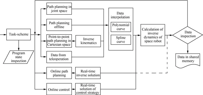
Fig.4 Functional diagram of the central controller simulator.

Fig.5 Functional diagram of the joint controller simulator.

where s is the position,sfand s0are the final and initial values,respectively,and tfis the terminal time.
6.2.1.Example 1:Satellite base attitude disturbance minimization
In this example,a comparison to analyze the proposed nullspace based solution and the Lagrange multiplier based weighted pseudoinverse solution is made.The main task is the end-effector path tracking task,while the optimization task is the reaction torque plus joint torque minimization.Suppose that the desired end-effector Cartesian position (x,y,z)and posture (α,β,γ)are divided into 4 cases:the first case is(-100,100,50)mm and(2°,2°,2°),and the other three cases are 1.5 times,double,and 2.5 times of the first case separately,that is,(-150,150,75)mm and(3°,3°,3°),(-200,200,100)mm and(4°,4°,4°),and(-250,250,125)mm and(5°,5°,5°).Thesefour cases are noted as 1×,1.5×,2×,and 2.5×,respectively,in Fig.6 and Fig.7,which show the corresponding tracking errors(Δx,Δy,Δz)and (Δα,Δβ,Δγ).
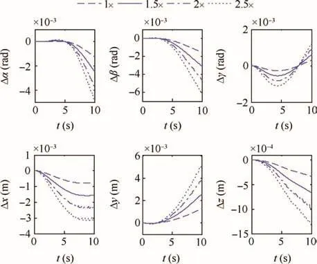
Fig.6 Tracking errors in Eq.(31)method.

Fig.7 Tracking errors in Eq.(38)method.
The results shown in Figs.6 and 7 demonstrate that the tracking errors in Eq.(38)method are smaller than those in Eq.(31)method,that is,the latter is more stable than the former.This is because the latter solution is without algorithmic singularity while the former is easy to divergent with the increasing task dependence.
Moreover,in order to verify the local optimization algorithm of the reaction torque plus the joint torque,assume that the end-effector Cartesian desired position (x,y,z)and posture (α,β,γ)are(-200,100,100)mm and(5°,5°,0°),respectively,the terminal time is 20 s,and in this process,the position and posture of the end-effector are shown in Fig.8,while the base relative orientation (ψ1,ψ2,ψ3)and the base angular velocity (w1,w2,w3)are shown in Fig.9.Figs.10 and 11 show the reaction torque (Tx,Ty,Tz) and the jointtorque τi,i=1,2,···,7 curves,respectively.In the following,case 1 represents path tracking control without torque optimization and case 2 represents path tracking control with torque optimization.

Fig.8 Position and posture of the end-effector.

Fig.9 Relative orientation and angular velocity of the base.
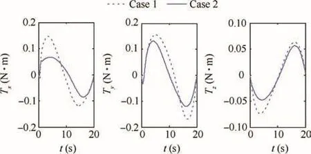
Fig.10 Reaction torque acted on the free-floating base.
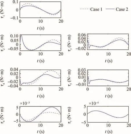
Fig.11 Joint torque of 7 joints in the base attitude minimization control.

Fig.13 Attitude of the base and the position of the end-effector.

Fig.14 Joint torque of 7 joints in base attitude adjustment control.

Fig.12 Tracking errors of base attitude adjustment and end-effector position tracking tasks.
From Fig.8,it can be seen that the optimization of the reaction torque plus the joint torque will have a little in fluence on the end-effector path tracking.Besides,from Fig.9,the final base attitude is(0.094,0.123,-0.062)rad if no optimization is made,but with reaction torque based optimization control,the base disturbance is(0.057,0.078,-0.039)rad,and the corresponding base angular velocity is reduced,which is caused by the optimization of the reaction torque shown in Fig.10.Moreover,Fig.11 shows the curves of the joint torque of 7 joints,and it can be recognized that the joint torque is reduced to some degree.From the above results,we can see that the reaction torque is an important index to measure the satellite base attitude disturbance.
6.2.2.Example 2:Satellite base attitude adjustment
In this example,a set of experiments is performed to make it clear about the difference between the reaction torque based active control and the rotational momentum based solution for base attitude control of a space robot.Four situations are considered:the first situation is that the desired base attitude (ψ1,ψ2,ψ3)is(1°,1°,0°)and the desired end-effector displacement(x,y,z)is(20,45,30)mm,while the other cases are double,triple,and quadruple of the first case separately.Take the first situation for example,the desired reaction torque is computed by the desired angular velocity and angular acceleration.Fig.12 shows the tracking errors.
Fig.12 reports the results obtained from the reaction torque based solution which overwhelm those obtained from the momentum based solution.In the four cases,the accuracy of the former solution is higher than that of the latter solution,and the former solution is more stable.This is because the former solution is dynamics-level control considering the centrifugal force,while the latter solution is just a second-order kinematics based control.
Furthermore,assume that the desired satellite base attitude(ψ1,ψ2,ψ3)is(1°,1°,0°)and the end-effector desired position (x,y,z)is(-40,-80,50)mm.Fig.13 shows the curves of the main tasks,and Fig.14 shows the optimization effect of the joint torque.
From the above results,the real motion of the space robot agrees with the desired planned trajectory,and it is obvious that the reaction torque based active control can achieve satellite base attitude adjustment effectively.The joint torque optimization will have a little influence on the base attitude control.The multiple dynamics related task is implemented simultaneously,among which the reaction torque is regarded as the active control input value and the joint driving torque is viewed as the optimization task.
7.Conclusions
(1)In this paper,a novel way is proposed to derive the analytical form of a reaction torque acted on a satellite base’s centroid.Besides,a reaction torque null-space is obtained on the basis of the analytical form of the reaction torque.Furthermore,an in-depth analysis of the relationship between the RTNS and the RNS is made.
(2)The reaction torque can be viewed as an optimization index to achieve satellite base attitude disturbance minimization,and this reaction torque based inactive control strategy is of vital importance in the generalized Jacobian based Cartesian task control when most of the DOFs are occupied.
(3)If redundant DOFs are abundant to achieve reaction torque based active control,the reaction torque can be utilized to achieve satellite attitude control,and the relationship between the reaction torque based base attitude control and rotational momentum based base attitude control is elaborated in this paper.
(4)A real-time simulator under Linux/RTAI of a freefloating space robot is built to verify the online usage of the proposed method.
Acknowledgements
This project was supported in part by the National Program on Key Basic Research Project 973 Program under Grant 2013CB733103 and the Program for New Century Excellent Talents in University under Grand NCET-10-0058.
1.Flores-Abad A,Ma O,Pham K,Ulrich S.A review of space robotics technologies for on-orbit servicing.Prog Aerosp Sci 2014;68:1–26.
2.Xu W,Liang B,Xu Y.Survey of modeling,planning,and ground verification of space robotic systems.Acta Astronaut 2011;68(11):1629–49.
3.Moosavian SAA,Papadopoulos E.Free-flying robots in space:an overview of dynamics modeling,planning and control.Robotica 2007;25(5):537–47.
4.Wen Z,Wang Y,Kuijper A,Di N,Luo J,Zhang L,et al.On-orbit real-time robust cooperative target identification in complex background.Chin J Aeronaut 2015;28(5):1451–63.
5.Huang P,Wang D,Meng Z,Zhang F,Guo J.Adaptive postcapture backstepping control for tumbling tethe red space robot-target combination.J Guidance Control Dyn 2016;39(1):150–6.
6.Dubowsky S,Papadopoulos E.The kinematics,dynamics,and control offree-flying and free-floating space robotic systems.IEEE Trans Robot Autom 1993;9(5):531–43.
7.Zhang L,Jia Q,Chen G,Sun H.Pre-impact trajectory planning for minimizing base attitude disturbance in space manipulator systemsfora capturetask.Chin J Aeronaut2015;28(4):1199–208.
8.Fernandes C,Gurvits L,Li ZX.Attitude control of space platform/manipulator system using internal motion.Space robotics:dynamics and control.Springer;1993.p.131–63.
9.Jin M,Zhou C,Liu Y,Liu H.Cartesian path planning for base attitude adjustment of space robot.In:IEEE international conference on mechatronics and automation;2015 Aug 2–5;Beijing,China;IEEE Press;2015.p.582–7.
10.Huang P,Wang M,Meng Z,Zhang F,Liu Z.Attitude takeover control for post-capture of target spacecraft using space robot.Aerosp Sci Technol 2016;51:171–80.
11.Huang P,Wang D,Meng Z,Zhang F,Guo J.Adaptive postcapture backstepping control for tumbling tethe red space robot–target combination.J Guidance Control Dyn 2015;39(1):150–6.
12.Dubowsky S,Torres M.Path planning for space manipulators to minimize spacecraft attitude disturbances.In:IEEE international conference on robotics and automation 1991.IEEE Press;1991.p.2522–8.
13.Vafa Z,Dubowsky S.On the dynamics of space manipulators using the virtual manipulator,with applications to path planning.Space Robotics:Dynamics and Control.Springer,1993.p.45–76.
14.Nakamura Y,Mukherjee R.Nonholonomic motion planning offree- flying space robots via a bi-directional ap-proach.Space Robotics:Dynamics and Control.Springer.1993.p.101–30.
15.Fernandes C,Gurvits L,Li Z.Near-optimal nonholonomic motion planning for a system of coupled rigid bodies.IEEE Trans.Autom.Control 1994;39(3):450–63.
16.Nenchev D,Umetani Y,Yoshida K.Analysis of a redundant freeflying spacecraft/manipulator system.IEEE Trans Robot Autom 1992;8(1):1–6.
17.Nenchev DN,Yoshida K,Vichitkulsawat P,Uchiyama M.Reaction null-space control of flexible structure mounted manipulator systems.IEEE Trans Robot Autom 1999;15(6):1011–23.
18.Cocuzza S,Pretto I,Debei S.Reaction torque control of redundant space robotic systems for orbital maintenance and simulated microgravity tests.Acta Astronaut 2010;67(3):285–95.
19.Cocuzza S,Pretto I,Debei S.Least-squares-based reaction control of space manipulators.J Guidance Control Dyn 2012;35(3):976–86.
20.Cocuzza S,Pretto I,Debei S.Novel reaction control techniques for redundant space manipulators:Theory and simulated microgravity tests.Acta Astronaut 2011;68(11):1712–21.
21.Liegeois BA.Automatic supervisory control of the configuration and behavior of multibody mechanisms.IEEE Trans Syst Man Cybern 2010;7(12):868–71.
22.Yoshida Kazuya.Experimental study on the dynamics and control of a space robot with experimental free-floating robot satellite.Adv Robot 1994;9(6):583–602.
23.Menon C,Aboudan A,Cocuzza S,et al.Free-flying robot tested on parabolic flights:Kinematic control.J Guidance Control Dyn 2005;28(4):623–30.
24.Fujii H,Uchiyama K,Yoneoka H,et al.Ground-based simulation of space manipulators using test bed with suspension system.Chem Eng Commun 1996;19(5):985–91.
25.Krenn R,Schaefer B.Limitations of hardware-in-the -loop simulations of space robotics dynamics using industrial robots.European Space Agency-Publications-ESA SP,1999;440:681–6.
9 September 2016;revised 12 October 2016;accepted 22 December 2016
Available online 20 April 2017
Attitude control;
Base disturbance;
Dynamics modeling;
Reaction torque;
Real time simulator;
Space robot
*Corresponding author.
E-mail address:zhoucheng0818@sina.com(C.ZHOU).
Peer review under responsibility of Editorial Committee of CJA.
Production and hosting by Elsevier
http://dx.doi.org/10.1016/j.cja.2017.02.021
1000-9361©2017 Chinese Society of Aeronautics and Astronautics.Production and hosting by Elsevier Ltd.
This is an open access article under the CC BY-NC-ND license(http://creativecommons.org/licenses/by-nc-nd/4.0/).
©2017 Chinese Society of Aeronautics and Astronautics.Production and hosting by Elsevier Ltd.This is an open access article under theCCBY-NC-NDlicense(http://creativecommons.org/licenses/by-nc-nd/4.0/).
杂志排行

CHINESE JOURNAL OF AERONAUTICS的其它文章
- A novel stability prediction approach for thin-walled component milling considering material removing process
- Preparation of bimodal grain size 7075 aviation aluminum alloys and the ir corrosion properties
- Drag derived altitude aided navigation method
- Autonomous orbit determination using epoch-diff erenced gravity gradients and starlight refraction
- A compositional method to model dependent failure behavior based on PoF models
- Dynamic analysis of spinning solar sails at deployment process